
6Data Encryption Based on Chaotic Sequence
Chaotic signal has great potential in cryptography with special features like unpredictability, high complexity, easy implementation, and so on. Compared to other encryption methods, chaotic encryption is a kind of dynamic encryption. The processing speed is not related with the key length, so it has high efficiency. It can be applied in real-time signal processing or static encryption.
Chaos theory began to attract the attention of cryptographic community in the late 1980s. The idea of chaotic encryption was proposed by British mathematician Matthews [49]. On one hand, due to the loss of information in the iteration, the amount of information is gradually lost to zero, so it is impossible to predict the chaotic sequences correctly. On the other hand, the chaotic synchronization is the key to achieve the correct decryption. Because the computer system can accurately reproduce all the starting states, the synchronization algorithm of chaotic iterative system can be realized by computer process synchronization. This is a feature that a physical chaos model does not have. There is no need to use complex physical chaotic synchronization and control method. Therefore, since the 1990s, the chaotic sequence encryption has become an important research frontier of modern cryptography [112, 124–127].
There are two research directions in chaotic cryptography. One is the chaotic secure communication based on chaotic synchronization. The other is to construct a new stream cipher and block cipher using chaotic system. In this chapter, we first discuss the theory of chaotic cryptography, and then we study the data encryption algorithm based on chaotic sequences and explore the application of chaotic sequences in digital watermarking and image encryption.
6.1Chaos Cryptography
6.1.1Traditional Cryptography
According to different methods of the text data encryption, traditional cryptography can be divided into the sequence cipher system and the block cipher system [128].
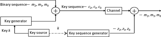
For sequence cipher, the original plaintext is transferred into plaintext data sequence first, and then the ciphertext sequence is obtained by employing the XOR operation with the key sequences. The generated ciphertext sequence is sent to the receiver. At the receiver, the plaintext sequence is recovered by using the XOR operation again. The sequence cipher encryption model is shown in Figure 6.1. There is no data expansion and error transmission in sequence cipher. Its advantages include good real-time performance and easy implementation for encryption and decryption. The security of the sequence is mainly dependent on the key sequence. If the key sequence is completely random, it is “one time pad,” which is not to be deciphered. However, in practice, one-time pad is very difficult to be realized, so the general encryption and decryption key sequence is pseudo-random sequence. One-time pad requires the key sequence has a sufficiently long period, good random statistical property, and greater linear unpredictability, and it also needs to meet the cipher principle about “diffusion” and “confusion” in the algorithm design.

For block cipher system, the data sequence x1, x2, . . ., is divided into x = (x1, x2, . . . , xm) groups with the length m, and each group (a vector with the length m) is converted into equal length data sequence y = (y1, y2, . . . , yn) (a vector with the length n) with the control of key sequence k = (k1, k2, . . . , kt). The principle diagram of block cipher is shown in Figure 6.2. The difference between block cipher and the sequence cipher is that each bit of the output is not only related to the input bit of the corresponding time, but also related to the plaintext digital with the length m. The block cipher has the following advantages. First, the block cipher is easy to be standardized. Second, synchronization is easy to be achieved for block cipher. A transmission error of a group data will not affect the others. The loss of a plaintext–ciphertext group will not affect the decryption of its subsequent groups. However, the block cipher cannot hide data patterns, and it cannot resist the attack of replay, embedding, and deletion. General block cipher algorithms include IDEA and DES.
6.1.2Relationship between Chaos Cryptography and Traditional Cryptography
Relation between chaos theory and traditional cryptography is summarized in Figure 6.3. The chaotic system is corresponding to cryptography algorithm. The extreme sensitivity of chaotic system to initial conditions and control parameters is corresponding to the diffusion of cryptography. Random and long periodic orbits of chaotic system can replace the pseudo-random signal in the cipher system. An initial value of chaotic map is spread to the whole phase space through the iteration, while the cryptographic algorithm generates the expected diffusion and confusion. Diffusion and confusion are the basic principles of design encryption algorithm. Diffusion means that the effects of each plaintext numbers are spread to multiple output cipher as much as possible so that the statistics characteristic of the plaintext can be concealed easily. Confusion means the statistics relationship between the plaintext and the ciphertext is complex. The parameters and initial values of the chaotic system are equivalent to the keys in the cipher algorithm. One important difference between chaotic system and cryptographic algorithm is that the traditional cryptographic algorithm is defined on finite set, while chaos cryptograph is defined on the real set, which means the traditional chaos theory is adapted to the continuous system, and this is the essential difference between them. In the chaotic system, Lyapunov exponent is a measure of the initial condition sensitivity, and Roland pointed out the possible link between it and security [129].
Chaotic encryption is different from the traditional encryption algorithm. The main difference is that the random signal used in chaotic encryption is generated by chaotic system. Chaotic signals are classified into continuous chaotic flows and discrete chaotic sequences. The former is used for the analog chaotic secure communication, and the latter is used for encrypted communication. The continuous signal generated by chaotic system can also be used as a discrete signal after it is made discrete, and the new Field Programmable Gate Array (FPGA) technology is used to design the hardware encryption system, which has become a new research hotspot [130]. In this section, we will discuss the information encryption based on discrete chaotic system.

6.1.3Principle of Chaos Sequence Encryption
Chaos sequence encryption belongs to the sequence cipher system, and its encryption principle is similar to that of the sequence cipher encryption. The difference is that the general sequence cipher uses the pseudo-random sequence generated by the circuit based on the shift registers, while the chaos sequence encryption uses the chaos sequence generated by chaotic system. In the early stage, the pseudo-random sequence generator is used to generate the key stream. An attacker can use the correlation analysis method to analyze and reconstruct the pseudo-random sequence effectively. Now, chaotic system is used to replace the pseudo-random sequence generator, which destroys the adaptive condition of the correlation analysis, and the security of the encryption algorithm is enhanced. The encryption principle is shown in Figure 6.4.
Encryption process is
and decryption process is
where K is the key stream generated by chaotic system. X is plaintext, and Y is ciphertext, and ⊕ is XOR operation.
It is a good encryption method by taking the chaotic sequence as key stream and using a one-time pad cryptosystem, but due to computer finite precision effect, chaotic sequence will eventually be periodic. How to produce a longer cycle, better random chaotic sequence is the key for an encryption algorithm, therefore, researchers have proposed a variety of schemes [131–133].

Figure 6.4: Block diagram of chaos sequence encryption/decryption.
The security of chaotic sequence encryption is mainly dependent on the key stream. In the chaotic encryption system, the random sequence {xi} generated by the chaotic system is taken as the key flow {ki}, and it does XOR operation with the plaintext data flow {mi}; thereby the encrypted data stream {ci} is generated. The plaintext data stream is binary, while there are two ways to produce the key stream {ki}. One is to use the original chaotic sequence {xi} directly, and the other is to use the processed data of the sequence {xi}. The former is actually the direct simulation of chaotic modulation communication technology, and the latter is the improvement of the former. There are a variety of processing methods for the original chaotic data by employing computer technology. For example, thousands of bytes at the beginning are discarded to overcome the transition process, or the sequence is obtained from the chaotic sequence according to a certain law, or a compound iterative algorithm is used to generate random sequences. So the randomness of the processed sequence will be greatly improved, which improves the anticracking ability of the encryption system.
The security performance of the encryption system is directly related to the size of the key space. For chaotic encryption system, many values can be used as a key, including nonlinear equations, initial values, system parameters, data-processing mode, and data encoding way. Obviously, the key space is huge, and the security is good.
6.2Data Encryption Algorithm Based on Chaotic Sequence
6.2.1Basic Requirements of Chaotic Encryption Algorithm
A good encryption algorithm not only can resist the brute-force attacks, but also has the ability of anti-plaintext attack, and superior temporal and spatial performance.
Resisting brute-force attack. The encryption system should have enough key space to resist the brute-force attack. Taking into account the extreme case, the user password is assumed to be a byte of all values, and then the number of possible values of the password is only 256. Assuming that a possible password needs only a second, it needs only 256 seconds to try all possible passwords. Obviously, the greater the password scope is, the more difficult the brute-force attack is.
Anti-chosen plaintext attack. Many cryptanalysts previously obtain the plaintext and ciphertext pairs through a variety of ways. Especially for data transmission on the network, it is easy to speculate a few hundred bytes of encrypted TCP data packets, which contain user name and password. Because a few beginning bytes of the data packets are often fixed, the encryption algorithm requires that it is still difficult to analyze the remaining plaintext and key, even when the cryptanalyst has a certain number of plaintext/ciphertext pairs.
Superior temporal and spatial performance. If an encryption algorithm consumes a lot of time, or consumes a large amount of computer memory, then it is not desirable. In fact, research results show that longer encryption time does not necessarily lead to greater strength of the encryption.
To ensure the security of the algorithm, we think that if a chaotic system is used in the encryption algorithm, it must be secure chaotic system.
Definition 6.1 Secure chaotic system: A chaotic system with discrete, zero correlation, mixed, robust and large parameter sets is defined as a secure chaotic system. It should be pointed out that for a chaotic encryption algorithm, the encryption system based on a secure chaotic system with the above properties is not necessarily safe, but when a chaotic system without the above properties is used for data encryption, the chaotic encryption system is bound to be weak. Next, we discuss it in detail.
- Discrete. It means that the chaotic system should be a discrete map, and the phase trajectory is not continuous. If the phase trajectory is continuous, the evolution trend of the system will be implied by any small neighborhood of the track, which may reduce the security of the algorithm.
- Zero correlation. It means that the cross-correlation of chaotic sequence is zero, and it is useful to resist the cipher correlation analysis. Zero correlation is associated with statistical properties of the system, and it indicates that the probability density of the system is uniform.
- Mixed. If plaintext is considered to be the initial condition, the mixed means that the effect of a single plaintext symbol is spread to many ciphertext symbols. Obviously, this property corresponds to the diffusion property in cryptography. A chaotic system with mixed property has better statistics, and when iteration number increases, the statistics of ciphertext is not dependent on that of plaintext. The statistics of ciphertext cannot be obtained by that of plaintext.
- Robustness. Robustness means that chaotic system can still keep the characteristics with small parameter perturbation. Most chaotic attractors are not stable, so a chaos encryption system based on the chaotic system without robustness has weak key property.
- Large parameter sets. Chaotic system should have large parameters and initial value space, and a global chaotic system is the best choice. In addition, an important index of cryptographic system is the Shannon entropy, which is used to measure the key space. For discrete time chaotic system, it is approximately log2k, where k is the number of keys. The larger the parameter space of the dynamical system is, the greater the k of discrete system is.
In summary, when we design a chaotic encryption system, the discrete chaotic system with robustness, zero correlation, mixed property, and large parameter set should be given priority. Although these five conditions cannot contain all security content, it is very high threshold for chaotic encryption. Strictly speaking, among the existing chaotic systems, no one is the safe chaotic system. Sheng et al. [88] proposed the elliptic chaotic system based on tangent delay, which has the above five conditions. However, this chaotic system is too complicated, and its mechanism also needs to be studied further. At present, Logistic map and its improvement have very good security features.
6.2.2Logistic Map and Its Statistics
One-dimensional discrete time nonlinear system is defined as
where xn ∈ V and n = 0, 1, 2, 3, . . . , xn is the system state. T: V → V is a map. If the initial value is x0, then we can get a sequence {xn, n = 0, 1, 2, 3, . . .} by iteration operation.
In this section, Logistic map is employed to design an encryption algorithm, and its equation is
where μ ∈ (0, 4], xn ∈ (0, 1). The Lyapunov exponent of the system with the parameter varying is shown in Figure 3.2. When, μ ∈ (3.5699 . . . , 4], it is chaotic.
For an encryption communication, both the initial value sensitivity and randomness of the signal are important. The stronger sensitivity and better randomness can lead to higher security. These characteristics can be described by probability statistics, mean value, autocorrelation, and cross-correlation, as shown in Section 3.1.1.
For Logistic map, when μ = 4, the mean value of the chaotic sequence is constant, and the autocorrelation is delta function and the cross-correlation is zero. Its probability statistics property is similar to that of the white noise with zero mean (as shown in Figure 6.5). So the Logistic map is suitable for information encryption. In addition, Logistic map basically satisfies the definition of the secure chaotic system. Therefore, Logistic map can be applied in digital communication and multimedia security.
6.2.3Chaotic Encryption Model and Algorithm
To encrypt digital signal, we need to turn the real number sequence {xk} to pseudorandom sequence [134], which is taken as a key sequence. The simplest way is to obtain a new integer by selecting a few digits after the decimal point of the xk. The encryption/decryption model based on Logistic map is shown in Figure 6.6.
Based on the model above, an encryption algorithm is designed, and the flow chart is shown in Figure 6.7. Taking into account the randomness and encryption speed, we chose the interval of pseudo-random sequence number N = 5. yi is 4th,5th, 6th, bit following the decimal point of xi, which can improve the ability to resist plaintext attack. In order to decrease the influence of the transition process, it is appropriate to discard the previous 2,000 iterations. In addition, it is difficult for users to remember the password with two floating-point values, so the first step includes a process of mapping the strings remembered by the user to x0 and μ. The encryption algorithm is presented as follows:

Figure 6.5: Probability density distribution of Logistic map.

- Initialize the Logistic map, and set the key x0 and μ.
- Iterate Logistic map for 2,000 times.
- yi is gotten by taking the 4th–6th bit of xi.
- Key sequence is obtained by yi mod 256.
- Do XOR operation with the plaintext or ciphertext.
- Judge whether encryption/decryption is complete; if it is incomplete, repeat steps 3–5 after 5 iterations of Logistic map. Otherwise, exit encryption system.

6.2.4Implement of Encryption Algorithm Based on Chaotic Sequence
Based on the proposed encryption model and encryption algorithm, we developed the data encryption software by using VC.Net in Visual Studio.NET tool. VS.Net is a complete tools for the generation of Web ASP applications, Web services XML, desktop applications, mobile applications, etc. Programming languages use the functions of the .NET framework, which provides access to key technologies to simplify the development of Web ASP applications and Web services XML. VS.Net employs MFC (Microsoft Foundation Classes) program method. It makes full use of the advantages of oriented object technology for which there is little need to be concerned about the implementation details of an object when we are programming. At the same time, the strong function of the various objects in the class library can complete most of the program functions, and it effectively ensures that the program is good for debugging.

We use Microsoft Visual C++ to develop the core algorithm. The software size is controlled within 1.5M for facilitating users to download. This software is composed of the main control module, the chaotic key sequence generation module, and the file encryption/decryption module. The secret relationship among the modules is shown in Figure 6.8.
6.2.4.1File Encryption/Decryption Module
This module provides three functions: TranslateKey, EncryptFile, and DencryptFile. The three interfaces provide a certain degree of abstraction to the main control module. The main control module does not need to be concerned about the details of the underlying file encryption, and it only needs to get the encrypted file and the user password. The specific encryption/decryption process is completed by the file encryption module.
The test procedure of the parameters is accomplished by the algorithm using these parameters, and several standard error codes are defined by the main control program. When an error occurs, the algorithm can return the standard error code and its specific error information code. The format of the error code is DWORD iError. The high sixteen bits are standard error code, which can be extracted by the HIWORD of the main control program, while the low 16 bits are custom error information codes. In addition, a standard procedure for obtaining the error description information from the error information code is also included in order to report to the user and realize the software’s “self description.”
After the standard encryption/decryption file method is provided, it is free to change the underlying encryption algorithm and will not affect the main control module, which makes the software version more flexible to upgrade.
6.2.4.2Chaotic Sequence Generation Module
This module includes two functions: MapKey and GetNextKey. The former can set two parameters of the logistic map and check the parameters to ensure they are within reasonable range. The latter is used to get the next encryption key. This module is transparent to the main control module, and it is also the general module of chaotic encryption/decryption. It contains two global variables to record the parameters of logistic map set by the encryption/decryption module. One key is obtained by 5 iterations of the generating function. Experiments show that the design is very successful.
6.2.4.3Main Control Module
It is the most challenging part in the whole design because the software does not contain too many user interaction processes, and users need not submit too much information. The software is suitable to design to be anti-traditional with relatively new interface form. At the same time, because this program is user oriented, and it costs a long time when large data files are encrypted, the multithread technology should be employed to separately implement the user interface process and the encryption process. The interface display thread can query the working state and progress of the underlying work thread at scheduled time and report them to the user.
On the Windows platform, the basic unit of interaction with the user is the application window, so we design a corresponding window in each interactive stage. This independent design for each state can make the process of design and implementation relatively intuitive, and maintenance and optimization of the process will become easier.
The interaction between the users and the main control module includes the following several aspects: the users start the application; the users choose the file encryption or the file decryption; the users select the plain text file and the cipher text file; the users enter the password; and the encryption/decryption process is completed.
The window procedure mentioned above can be described by a state transition diagram as shown in Figure 6.9. Each state can be represented by a window, and each state conversion can be achieved with displaying or hiding the window. For the three groups, key input 1 and key input 2, file input 1 and file input 2, as well as the encryption progress 1 and the encryption progress 2, each group can be achieved with the same window, and we only need to record the current state. To display and hide the window, two functions (FadeIn() and FadeOut()) are added to each window class. FadeIn() is used to display the window, while FadeOut() is used to hide the window. The window fade and other special effects can be achieved by modifying the two standard processes.

6.2.5System Performance Analysis
6.2.5.1Analysis of Anticracking Ability
The key of cryptanalysis is to obtain the initial value x0 or parameter μ set by the user. The two values will be taken as floating-point number. If the effective value of a computer floating-point number is 16, then 30 bits are uncertain for the two numbers, and the possible combinations are 1030, while key combination of DES encryption algorithm is 256. Obviously 30 > 56 log 2. So the proposed algorithm can effectively resist brute-force attack.
To improve the adaptability of chosen plaintext attack, we use interval sampling method. If the interval number is one, then the relationship between xn and xn+1 is
It is a quadratic equation with one unknown. If the interval number is N, then the relationship between xn and xn+1 becomes one-dimensional equation of N degrees.
6.2.5.2Statistics Distribution of Ciphertext
Whether the statistics distribution of encrypted data is uniform is an important index to evaluate the encryption algorithm.
Theorem 6.1: If the chaotic sequence is completely random, the encrypted data is subject to the uniform distribution.
Proof. The plaintext and chaotic (key) sequence is considered as a byte of data stream, and we take a byte of plaintext m and key k randomly from them. Supposing that the value of m is different, that is, the probability is unequal for one bit to be “0” or “1,” then the appearance of “0” or “1” is independent. If the probability of “1” is p, then the probability of “0” is 1–p. The chaotic (key) sequence satisfies the performance of white noise for the ideal state; that is, “0” or “1” appearing at each bit has the same probability of 0.5, and then the probability of appearing “1” in the ith bit of ciphertext c is
The probability of appearing “0” in the ith bit of ciphertext c is
Obviously, the probability distribution of the ciphertext is uniform. ∎
6.2.5.3Experiment Results
The chaotic encryption software is designed by employing modular design method and multithread technology. If both communication sides have the same key and the encryption software, they can realize the encryption transmission of the information.
The software can encrypt not only the text file, but also the bitmap file. Figure 6.10 is the result of a bitmap encryption. Figure 6.10(a) is the plaintext image. Figure 6.10(b) is the encrypted image. Figure 6.10(c) is the decrypted image. Compared with Figure 6.10(a), Figure 6.10(c) is clear and accurate without distortion. Figure 6.10(d) is the decryption image with small deviation of key, and obviously it cannot be decrypted correctly.
Data encryption standard (DES) is a relatively good symmetric encryption algorithm. Rivest-Shamir-Adleman (RSA) proposed by Rivest, Shamir, and Ademanis is an outstanding representative of the public key algorithm. Now, the chaotic encryption algorithm is compared with the DES and RSA encryption algorithm by encrypting/decrypting Lena image, and the results are shown in Table 6.1. Obviously, chaotic encryption has advantages in encryption speed and security.
It should be pointed out that the software is mainly suitable for static data encryption. In order to realize the real-time data stream encryption, we must solve the problems, such as fault tolerance, synchronization, delay, and so on, which will be researched in the seventh chapter.
6.3Binary Watermark Image Encryption Algorithm Based on Chaos
Chaotic sequence is a kind of pseudo-random sequence. It has a simple form and is very sensitive to initial conditions and has statistical properties of white noise. These characteristics can meet the requirements of the security of digital watermarking technology. Therefore, chaos-based digital watermarking is becoming a hot topic.

Figure 6.10: Image encryption results: (a) original image; (b) encrypted image; (c) correct decryption image; and (d) decryption image with key change for 10–14.
Table 6.1: Performances of DES, RSA, and chaotic encryption algorithm.

6.3.1Improvement of Chaotic Pseudo-Random Sequence Generator
Aiming at the defects of various chaotic sequence generators, many researchers have put forward the improvement schemes, which mainly include the following two methods.
6.3.1.1Improvement of Traditional Chaotic Sequence Generator
This method focuses on improving the traditional chaotic sequence implementation algorithm, and it includes two types. One is to improve the single traditional chaotic sequence, such as piecewise linear chaotic sequence, Chebyshev chaotic sequence, and so on. In order to enhance security, we can consider using multiple chaotic systems. For example, the output of the two chaotic systems can be combined to generate pseudo-random bit stream, such as the combination of logistic map and tent map. In addition, the new algorithm for generating uniform pseudo-random number is studied [135], and spatiotemporal chaotic system is tried to generate pseudo-random numbers [136].
6.3.1.2New Secure Chaotic System
At present, along with the emergence of the improved algorithm of the traditional chaotic sequences, some new chaotic sequence generators have been put forward. Among them, the TD-ERCS chaotic system has good cryptographic properties due to its discreteness, global chaos, global zero correlation, huge parameter and initial value space, and strong anti-degradation ability [137, 138]. So TD-ERCS chaotic system is a chaotic system with great potential application.
6.3.2Binary Watermark Image Encryption Algorithm Based on TD-ERCS Map
Binary image processing algorithm is simple and easy to understand and realize, and has fast calculation speed and other features. A lot of digital watermarking system uses binary image as the watermark information, so the watermark is more intuitive. Here, TD-ERCS chaotic map is used to encrypt the watermark image.
6.3.2.1TD-ERCS Map
TD-ERCS map is a new global two-dimensional discrete chaotic system. It is an ideal model for information encryption with zero correlation, stable probability distribution, and good randomness of the sequence. Set the system parameter μ(0 < μ < 1), initial values x0(–1 ≤ x0 ≤ 1) and α(0 < α < π), tangent delay m(m = 2, 3, 4, 5, 6, . . .). TD-ERCS map is described in Section 3.1.4. The system can generate two independent sequences xn (|xn| < 1) and kn (|kn| < 1).
6.3.2.2 Design of Encryption Algorithm
Double-precision floating-point number is used in TD-ERCS iteration, and the data format is shown in Figure 6.11. The data occupies 8 bytes of storage space, and it is composed of the following three parts:
- Sign bit s. s represents the sign of the number; it is one bit by which 0 means positive, and 1 means negative.
- Exponent bit e. e represents exponential order code, and it is 11 bits. It is unsigned number (0 < e < 2047).
- Tail bit f . f is the fractional part of the tail number, 52 bits.
If W is a binary watermark image, and the pixel size is M×N, the encryption algorithm is as follows:
- Taking TD-ERCS system parameters (μ, x0, α, m) as the key, chaotic sequence is generated by eq. (3.17). Sequence {xn} is composed of ‖M × N /52 numbers generated by the chaotic sequence (Considering security, the initial segment of the sequence is not used).
- Binary sequence {bi} is obtained from f, 1 ≤ i ≤ M × N.
- The binary watermark image is encrypted with the binary sequence {bi}; encryption operation is
where ⊕ is XOR operation. At the receiving end, input the same key, and by repeating the encryption algorithm, the image can be decrypted correctly.
6.3.3Performance Analysis of Encryption Algorithm
The security of encryption algorithm mainly depends on the key, while the key has a great relationship with the key space, the key sensitivity, and the complexity of the algorithm. Here we discuss the security of the algorithms.
6.3.3.1Key Sensitivity Analysis
To confirm the effectiveness of the algorithm, a watermark image ![]() with the size of 64 × 64 is selected. The key is set as μ = 0.7123, x0 = 0.7654, α = 1, 000, and m = 9. The encryption effect is shown in Figure 6.12. Figure 6.12(a) is the original image. Figure 6.12(b) is the encrypted image, and Figure 6.12(c) is the decrypted image with correct key. Figure 6.13 shows the sensitivity to the key. For decryption, the original watermark images are unable to be decrypted with small deviation of the key.
with the size of 64 × 64 is selected. The key is set as μ = 0.7123, x0 = 0.7654, α = 1, 000, and m = 9. The encryption effect is shown in Figure 6.12. Figure 6.12(a) is the original image. Figure 6.12(b) is the encrypted image, and Figure 6.12(c) is the decrypted image with correct key. Figure 6.13 shows the sensitivity to the key. For decryption, the original watermark images are unable to be decrypted with small deviation of the key.

Figure 6.11: IEEE 754 double-precision binary floating-point format.

Figure 6.12: Image encryption and decryption: (a) original image; (b) encrypted image; and (c) decrypted image with correct key.

Figure 6.13: Decrypted image with wrong keys: (a) μ deviation with 10–16; (b) x0 deviation with 10–16; (c) α = 1, 001; and (d) m = 10.
It can be seen from the experiment results that this algorithm is very sensitive to the key. If a slightly modified key is used to decrypt the cipher image, the decryption fails completely. The key contains four dependent parameters: μ, x0, α, m. μ, and x0 are in real numbers. So the algorithm is secure with large key space.
6.3.3.2Scrambling Degree Analysis
The gray difference between pixels and their adjacent pixels is defined as

where G(x, y) is the gray value of ![]() is the gray value of (x, y) at the four positions: up and down, and left and right.
is the gray value of (x, y) at the four positions: up and down, and left and right.
If the size of the image is M × N, the average adjacent pixel difference of the image is described as

and adjacent pixel scrambling degree is defined by
where E and E ′ are the average adjacent pixel difference before and after scrambling, respectively. The range of GDD is (–1, 1). The larger the range is, the better the image scrambling is.
Figure 6.14 presents three binary images, and the sizes of them are 64 × 64. The evaluation of adjacent pixel scrambling is listed in Table 6.2.
E (GD(x, y)) is the average adjacent pixel difference of original image I. The value of E(GD(x, y)) is about 0.1, which shows that the original image has large pixel values in close smooth area, and the average gray difference of adjacent pixels is small. E′(GD(x, y)) is the average adjacent pixel difference of encrypted image I′. In Table 6.2, E′ (GD(x, y)) is greatly different from E (GD(x, y)), which indicates each pixel tends to have random distribution, and the average adjacent pixel difference varies greatly. GDD (I, I′) is larger than 0.5, which illustrates that the adjacent pixel scrambling degree is bigger, and the encryption effect is very well.

Figure 6.14: Binary images: (a) image a; (b) image b; and (c) image c.
Table 6.2: Evaluation of adjacent pixel scrambling.

6.3.3.3 Analysis of Anti-Brute-Force Attack
The user password is binary sequence K = kμkx0kαkm. kμ, kx0, and kα have the same data length. They are used to generate floating-point numbers μ, x0, and α. km is used to generate integer m. Let the length of km be 12 bits, and then m is generated by

If the computer word is 32 bits, and the precision (floating-point number) is 10–9, then the key space is about 1027 × 212 ≈ 1030, which is large enough to resist brute-force attacks.
The results of experiments and performance analysis show that the binary image watermarking encryption algorithm based on the TD-ERCS map is good with large key space, high key sensitivity, and high security. Therefore, if the encryption algorithm is applied to the watermarking algorithm, it can ensure the security of the watermark.
6.4Color Image Watermarking Algorithm Based on Chaotic Map and Wavelet Transform
As a new technology of copyright protection and content authentication, digital watermarking has become a hot topic. The application of chaos in digital watermarking technology mainly includes two aspects. One is the pretreatment of watermark information, such as the following: (1) digital watermark information is embedded into the image directly, (2) the watermark information is encrypted by chaotic sequence, and (3) binary image watermarking is encrypted or scrambled. The other is the watermark embedding process encryption, such as the choice of the position, intensity, etc.
In this section, a novel color image watermark algorithm based on discrete chaotic map and 2-D discrete wavelet transform is proposed. The proposed algorithm uses a meaningful binary image as the watermark, which increases the watermark provability. TD-ERCS discrete chaotic system and the commonly generalized Arnold map are used to encrypt the watermark image and determine the embedding position, which improves the security of the watermark image. The watermark is embedded by wavelet transform. Simulation experiments and performance analysis show that the proposed algorithm not only can resist some common image processing and noise interference, but also can resist the image shear, small rotation, histogram modification, and joint attack with good invisibility, robustness, and security.
6.4.1Wavelet Transformation Algorithm and Its Application
Wavelet transform is an ideal mathematical tool for local analysis, which has been widely used in signal analysis, speech synthesis, image recognition, computer vision, data compression, seismic exploration, and atmosphere and ocean analysis.
6.4.1.1Continuous Wavelet Transform
If ψ(x) is a real-valued function, and its spectrum ![]() (w) satisfies the condition
(w) satisfies the condition
then ψ(x) is called a basic wavelet. ψ(x) is similar to impulse response of a band-pass filter. Assuming that a and b denote expansion and translation operation of ψ(x), respectively, then by the translation and expansion of the basic wavelet, the wavelet basis functions can be generated as
where a ∈ R, b ∈ R, a > 0.
If f(x) is a square integrable function, and f(x) ∈ L2(R), then the continuous wavelet transform of f(x) is defined as
It indicates the decomposition of f(x) on function Wf (a, b), and it also can be considered as f(x), which is filtered by using a band-pass filter. The wavelet inverse transform definition is
It should be noted that ψa,b(x) is not orthogonal, and it has very large redundancy. In addition, the basic wavelet is not unique.
6.4.1.2Two-Dimensional Discrete Wavelet Transform of Image
Digital image is a discrete two-dimensional signal. The common method for two-dimensional discrete wavelet transform is to let the two-dimensional scaling function be separated; that is,
where ϕ(x) is one-dimensional scaling function. If ψ(x) is the corresponding wavelet, then three two-dimensional basic wavelets are

The scaling function ϕ(x) can be treated as a low-pass filter, while the wavelet function ψ(x) is the high-pass filter of the same layer, and the function set is
It is the standard orthogonal on the basis of L2(R2), and j, l, m, and n are integers.
f0(x, y) is an image with the size N × N, and N is the power of 2. j is resolution parameter, and the scale is 2j. When j = 0, the scale of the original image is 1, and it is a resolution signal for zeroth layer. The resolution reduces by halve with the value j increasing by 1.
The two-dimensional discrete wavelet transform of an image is carried out as follows. In each layer of the transformation, the image is decomposed into four small images with same size. Each of them is obtained by the inner product of original image with a basic wavelet and 2 times interval sampling in x and y directions. The first layer (j = 1) wavelet transform is

For the transformation of subsequent levels (j > 1), four same interval samplings and filter operation are performed at each layer. ![]() is decomposed into four smaller images on the scale of 2j+1 in the same way. The inner product in the form of convolution is
is decomposed into four smaller images on the scale of 2j+1 in the same way. The inner product in the form of convolution is

Because the scaling function and the wavelet function are separable, each convolution can be decomposed into one-dimensional convolution on the row and column of ![]() as shown in Figure 6.15. h0 is the low-pass filter, and h1 is the high-pass filter. ↓2 is two times sampling, and
as shown in Figure 6.15. h0 is the low-pass filter, and h1 is the high-pass filter. ↓2 is two times sampling, and ![]() is the low-frequency components after wavelet decomposition.
is the low-frequency components after wavelet decomposition.![]() and
and ![]() are the high-frequency detail components of horizontal, vertical, and diagonal directions, respectively.
are the high-frequency detail components of horizontal, vertical, and diagonal directions, respectively.

Figure 6.15: Diagram of wavelet decomposition.

Obviously, the wavelet transform of the image is to filter the image in the horizontal and vertical directions by using the filter module. At each level, ![]() contains the low-frequency approximation components of the previous layer.
contains the low-frequency approximation components of the previous layer. ![]() and
and ![]() contain the high-frequency detail components of horizontal, vertical, and diagonal directions, respectively.
contain the high-frequency detail components of horizontal, vertical, and diagonal directions, respectively.
Similarly, the two-dimensional inverse wavelet transform of the image is shown in Figure 6.16, where ⊕ represents convolution.
6.4.1.3Application of Wavelet Transform for Image Watermarking
The original image, three-level wavelet decomposition diagram, and structure diagram are shown in Figure 6.17. Three high-frequency bands HLi, LHi, and HHi(i = 1, 2, 3) and a low-frequency band LL3 are obtained by three-level wavelet decomposition of the original image. According to the characteristics of image wavelet decomposition, the low-frequency band LL3 is the best approximation of the original image under the largest scale and minimum resolution decided by wavelet transform decomposition series. Most energy of the image is centered in the low-frequency band. High-frequency band series are the details of image at different scales and different resolution. These bands are not unrelated from the perspective of multiresolution. For each high-frequency band, they are described from being coarse to fine for the same edge, contour and texture information of an image in different directions, different scales, and different resolutions, and there are some relations between them.

Figure 6.17: Three-level wavelet decomposition of image; (a) original image; (b) three-level wavelet decomposition; and (c) three-level wavelet decomposition structure.
Compared with other transforms, the image watermarking algorithm based on wavelet transform has many good characteristics, such as spatial scale localization, multiresolution representation, adaptation to human visual system, different spatial support region, large selectivity, meeting the demand of security, and simple calculation.
6.4.2Design and Implementation of Watermark Embedding and Extraction Algorithm
6.4.2.1Principle of Watermarking Algorithm
The principle of watermark algorithm is shown in Figure 6.18. To improve the security of the embedded watermark image, the chaotic sequence generated by TD-ERCS discrete chaotic system is used to encrypt the watermark image. According to the visual characteristics of the human eyes, the human eyes are not sensitive to the blue component of the RGB image, and thus the watermark is embedded in the blue component of the color image.
Based on the advantages of embedded watermark of high- and low-frequency parts in the wavelet domain, the encrypted watermark information frequency is embedded into the four sub-bands of the blue component of the host image. The embedding position is determined by the chaotic sequence generated by the generalized Arnold map. Watermark information is spread to the low-frequency and high-frequency coefficients of the three-level decomposition. Because the original image is needed for watermark extraction, it belongs to the nonblind extraction.

6.4.2.2Choice of Watermark Embedding Position
To embed the watermark into the color image, the first question is to embed the watermark into which component of the color image. There are many color image models, including the RGB model, YUV model, YIQ model, YCbCr model, etc. The RGB model is the most commonly used. A pixel of true color image has three bytes of R, G, and B data structures, which represent the size of red, green, and blue. Bmp image is presented with the RGB method. Based on the brightness equation, gray image transformed from color image is defined by
According to eq. (6.22), the watermark is embedded into the blue component of the color image.
After the blue component of the color image is decomposed by three-levelwavelet, a low-frequency band and nine high-frequency bands are obtained. The watermark can be embedded into the low-frequency part or the high-frequency part of the wavelet domain [139]. Here, the encrypted watermark is randomly embedded into the four sub-bands of three-level wavelet decomposition in the blue component. The watermark is spread to the deepest frequency and high-frequency coefficients of the three level-wavelet decomposition.
6.4.2.3Selection of Wavelet Base Function
In the design of digital watermarking algorithm based on wavelet transform, the first question is how to choose proper wavelet base function to ensure the robustness and invisibility of the watermarking system. The wavelet base function determines the efficiency and effect of wavelet transform. Different wavelet has different properties, which will lead to the different distribution characteristics and the energy convergence characteristics of wavelet coefficients, and the robustness of the watermark is also different.
At present, biorthogonal wavelet is widely used in the image processing due to the characteristics of regularity, compactness, and symmetry. The research shows that the Harr wavelet has good performance, and it is a good choice in the digital watermarking algorithm. The Harr wavelet is defined as

Compared to other orthogonal wavelet bases, the Harr wavelet has some advantages as follows:
- The support length is the shortest.
- The computation complexity of decomposition and reconstruction is lower than that of other wavelets, and it results in the rapid implementation.
- When the Mallat algorithm is used, the boundary extension is not required. There is no edge effect due to the limited length of the image signal.
- When the image is divided into several mutual disjoint image blocks with the same size, each image block has a corresponding independent wavelet block, and these wavelet blocks do not intersect each other.
Based on the discussion above, we select Haar wavelet as the wavelet basis function.
6.4.2.4General Arnold Map
Arnold map is described as
where x mod 1 means only the decimal part of x is obtained. The phase space of (xn, yn) is limited in [0, 1] × [0, 1]. The matrix form of eq. (6.24) is
where C is a matrix, and |C| = 1. So Arnold map is a guaranteed area map. At the same time, the Arnold map is the one-to-one map. That is, each point in the unit matrix uniquely transforms to the other point within the unit matrix.
Now, we generalize the phase space of the Arnold map to be {0, 1, 2, . . . ,M – 1} × {0, 1, 2, . . . ,M – 1} and generalize the equation to be two-dimensional reversible area preserving equation, which is described as
where a, b, c, and d are positive integers, and the area preserving requires |C| = ad– bc = 1. Based on the condition, only three parameters of a, b, c, and d are independent.
The generalized Arnold map is still chaotic. We use the generalized Arnold map to generate the embedding position of the watermark. Taking the pixel coordinates (x, y) of the watermark image as initial values, and taking the three independent parameters and iteration number k of the coefficient matrix C as the key, the generated iterative results (x′, y′) are used as the embedding position of the watermark in (x, y). When iteration number is large enough, the corresponding embedding position will be greatly separated for any two adjacent watermark pixels.
6.4.2.5Watermark Embedding and Extracting Algorithm
H is the original host image with the size N × N, and W is binary watermark image with the size M × M. The watermark embedding algorithm is described as follows.
- Blue component is extracted from the original color image. Wavelet decomposition coefficient
 is obtained by the three-level wavelet decomposition of the blue component. For
  l is wavelet decomposition level (l = 1, 2, 3), and θ = 0, 1, 2, 3 represent the wavelet coefficients of the low-frequency, horizontal, vertical, and diagonal directions, respectively. A new matrix with size (N/4)×(N/4) is got by merging the third-level coefficient matrix of the low-frequency, horizontal, vertical, and diagonal directions, and it is marked as F = {f(x, y), 1 ≤ x ≤ N/4, 1 ≤ y ≤ N/4}.
 - The watermark image W is encrypted by encryption algorithm based on TD-ERCS map. The encrypted watermark image is denoted by W′ = w′(i, j), 1 ≤ i ≤ M, 1 ≤ j ≤ M{.
- Set the three independent parameters of generalized Arnold map and iteration numbers k.
- For the watermark pixel w′(i, j), let x0 = i, y0 = j. The embedding position (p, q) in the matrix F is obtained by iteration k times of eq. (6.26).
- Embed watermark. The watermark pixels are embedded into the selected wavelet coefficients according to
where f(p, q) is the original wavelet coefficient. f ′(p, q) is the wavelet coefficient after embedding watermark. θ = 0, 1, 2, 3 represent wavelet coefficients of low-frequency, horizontal, vertical, and diagonal directions, respectively. α and β indicate the intensity of embedding watermark, which is determined by the specific watermark and the original image, and it needs trade-off between invisibility and robustness of the watermark.
6.Repeat steps (4) and (5) until all the watermark pixels are embedded. After the three-level wavelet inverse transform is carried out by employing all the wavelet coefficients, the blue component image with embedded watermark is obtained. Finally the color image embedded with watermark is obtained.
The watermark extraction algorithm is described as follows.
H∗ is the image waiting for detecting. First, we extract blue component of H ∗, and then the blue component is decomposed by three-level wavelet. A new matrix marked as F ∗ = {f(x, y)} (where 1 ≤ x ≤ N /4, 1 ≤ y ≤ N /4) is obtained by merging the coefficient matrix of the low-frequency, horizontal, vertical, and diagonal directions in the third level. Refer to steps (3)–(5) of the watermark embedding algorithm; the embedding position of the watermark is obtained by using the same key. The formula for extracting watermark is

where ![]() is the mth extraction watermark pixel. f(p, q) is the wavelet coefficients of the original image. θ = 0, 1, 2, 3 represent wavelet coefficients of low-frequency, horizontal, vertical, and diagonal directions, respectively. α, β indicate the intensity of embedding watermark. After extracting the watermark information, it is decrypted by the TD-ERCS map and the correct watermark is recovered.
is the mth extraction watermark pixel. f(p, q) is the wavelet coefficients of the original image. θ = 0, 1, 2, 3 represent wavelet coefficients of low-frequency, horizontal, vertical, and diagonal directions, respectively. α, β indicate the intensity of embedding watermark. After extracting the watermark information, it is decrypted by the TD-ERCS map and the correct watermark is recovered.
6.4.3Simulation and Performance Analysis
Based on Matlab platform, the watermark embedding and extraction is carried out on 24 bits true color Lena image with the size 512×512. The watermark image is the binary image ![]() with the size 64 × 64. The embedding strength is α = 41 and β = 59.
with the size 64 × 64. The embedding strength is α = 41 and β = 59.
The performances of the algorithm are analyzed, including invisibility, robustness, and security. To evaluate the concealment of the algorithm, we employ the peak signal-noise ratio (PSNR). The PSNR of the color images is defined as
where
where X′(i, j) is the image with embedded watermark, and X (i, j) is the original image, 0 < i, j ≤ N. The bigger the PSNR is, the better the invisibility is.
The robustness evaluation is between the original watermark W and the extracted watermark W′. Here, the methods of visibility and normalized correlation coefficient (NC) are employed.
Visibility is evaluated by observing the difference between the original watermark and the extracted watermark. Normalized correlation coefficient is defined as

where W′(i, j) is the extracted watermark, and W(i, j) is the original image. Obviously, 0 ≤ NC ≤ 1. The greater the NC is, the better the similarity between the original watermark and the extracted watermark is.
6.4.3.1Invisibility
First, we test the invisibility of the watermark. Figure 6.19(a) is the original image, and Figure 6.19(c) is the embedded watermark image. Obviously, human eyes cannot distinguish the difference between them. The embedded watermark image has good subjective quality. The PSNR of the embedded watermark image is 38.8074 dB with good objective quality. Figure 6.19(b) is the original watermark, and Figure 6.19(d) is the extracted watermark. The normalized correlation coefficient NC = 1, which illustrates that the two watermarks are identical.
6.4.3.2Robustness
The robustness of watermarking algorithm is to test the anti-attack ability. The sharpening, distortion, histogram equalization, contrast enhancement, and mosaic effect are completed by Photoshop CS3 Adobe.
(1) Anti-JPEG compression attack
JPEG lossy compression is applied to Figure 6.19(c). The test results of anti-JPEG compression attack capability are shown in Table 6.3. Q is the quality factor, and its range is 0 ∼ 100. The larger the Q is, the less compression distortion the image is. NC is the normalized correlation coefficient. The watermark images with Q = 70, 50, and 30 are extracted as shown in Figure 6.20. It can be seen that when Q varies from 100 to 50, NC is bigger than 0.8, which means the watermark image and the original watermark image are basically the same. The extracted watermark is still clearly distinguished when Q = 30. So the algorithm has strong ability of resisting JPEG compression.

Figure 6.19: Watermark invisibility experiment: (a) original image; (b) original watermark; (c) embedded watermark image; and (d) extracted watermark.
Table 6.3: Test of anti-JPEG compression attack capability.

(2) Antinoise attack
Figure 6.21 shows the noise attack test results. Figure 6.21(a) illustrates the watermark image and the extracted watermark from the 2% Gauss noise attack. The watermark image and the extracted watermark from the 4% salt-and-pepper noise attack are shown in Figure 6.21(b). The quality of the image has been seriously degraded, but we can still extract a clear watermark image. So the algorithm has a strong ability to resist noise attack.

Figure 6.20: Watermark image extracted from JPEG compression: (a) Q = 70; (b) Q = 50; and (c) Q = 30.

Figure 6.21: Experiments of antinoise attack: (a) watermark image and the extracted watermark from the 2% Gauss noise attack and (b) watermark image and the extracted watermark from the 4% salt-and-pepper noise attack.

Figure 6.22: Anti-filtering attack experiment: (a) extracted watermark after low-pass filtering experiment; (b) extracted watermark after median filtering experiment; and (c) extracted watermark after high-pass filtering experiment.
(3) Anti-filtering attack
The result of an anti-filtering attack is shown in Figure 6.22. When low-pass filtering, median filtering, and high-pass filtering are finished, the NC values are 1, 0.9976, and 0.9951, respectively.
(4) Anti-cutting attack
This algorithm is strongly robust to cutting. Figure 6.23 is the watermark image and the extracted watermark after cutting 1/4 or central 15% cutting. The NCs of Figure 6.23(a) and Figure 6.23(b) are 0.7956 and 0.8637, respectively.
(5) Anti-rotation attack
Rotation attack is the most representative geometric attack. As long as attacker makes a small geometric transform on the original image, such as the rotation of 0.1 degree, the pixel position almost changed completely. The owners cannot extract the watermark in the image, while people cannot see the difference between the attacked image and the original image. When the rotation angle is greater than 1, the human eyes can recognize the difference between the attacked image and the original image. At this situation, we can identify that the image has been tampered. The anti-rotation attack experiment results are shown in Figure 6.24. This algorithm can resist rotation attack with 0 to 0.6 degrees.
Besides the JPEG compression, noise attack, filtering attack, shear attack, rotation attack, and other common noise processing and attack, this algorithm can also resist histogram equalization, contrast enhancement, USM sharpening, distortion, mosaic effect, and some joint attacks. The experiment results are shown in Table 6.4.
6.4.3.3Security Analysis
The proposed watermarking algorithm has double security. On one hand, the attackers do not know the 3 independent parameters (a, b, and c) and iteration number k of the generalized Cat map. On the other hand, even though the correct watermark information is extracted, the original watermark image cannot be recovered without the TD-ERCS parameters (μ, x0, α, and m). The key is composed of (a, b, and c) and (μ, x0, α, and m), so the key space is large enough to resist the brute-force attack, and the algorithm has high security.

Figure 6.23: Anti-cutting attack experiment: (a) watermark image and the extracted watermark with 1/4 cutting of upper left corner and (b) watermark image and the extracted watermark with central 15% cutting.

Figure 6.24: Anti-rotation attack experiments: (a) watermark extracted from rotation with 0.2 degree; (b) watermark extracted from rotation with 0.4 degree; and (c) watermark extracted from rotation with 0.6 degree.
Table 6.4: Tests of anti-attack ability.

6.5Chaotic Image Encryption Algorithm
From the view of the data-processing methods, the image encryption technology can be divided into three categories: position replacement, value transformation, and its combination. From the view of signal processing, image encryption algorithm can be divided into spatial domain algorithm and frequency domain algorithm. Image encryption based on chaos is a kind of transformation of image data by employing chaotic sequence, which makes the visual difference between the transformed image and the original image. The visual difference here refers to the qualitative or quantitative differences in color, brightness, or outline. In this section, we focus on the chaos-based image encryption technique.
6.5.1Chaos-Based Image Encryption Technology
6.5.1.1Image Scrambling Based on Chaotic Map
Digital image scrambling transformation includes one-dimensional, two-dimensional, three-dimensional, and high-dimensional transformations. Objectively they should be one-to-one map, which means they are reversible transformations. The encryption can be achieved through the transformation, and the decryption can be achieved through the inverse transform. In order to provide a larger key space and a more efficient way to change the correlation between pixels, the encryption method based on high-dimensional chaotic systems has become a new research hotspot inrecent years. For designing a chaotic scrambling scheme, we should choose a suitable chaotic map. We think the following factors should be considered:
- Lyapunov exponent should be as large as possible. If the Lyapunov exponent is larger, the system is more sensitive to the initial value, and it is more suitable for image encryption.
- Control parameters should be as much as possible. For the chaotic cipher system, parameters are often used as key. Large parameter space can ensure a large key space to resist the brute-force attack.
- Chaos map should be a reversible one-to-one map to ensure the scrambling transformation is reversible.
- High-dimensional map should be given priority. If the system structure of high-dimensional chaotic system is more complex, then it can change the correlation between pixels more effectively.
When choosing the encryption parameters, the structure and characteristics of the chaotic system need to be fully investigated. For example, the weak key should be removed, and the parameters range should be determined, and the key space should be as large as possible. The chaotic maps usually applied in image encryption include Kolmogorov flow, two-dimensional Cat map, and two-dimensional Baker map. Some scholars extend the two-dimensional map to the three-dimensional map. When the three-dimensional map is used to scramble pixel, the scrambling speed becomes faster.
In the chaotic scrambling, the sensitivity to initial conditions corresponds to chaotic plaintext sensitivity. The larger the location of the plaintext varies, the smaller the correlation between the two adjacent pixels is. So it is more difficult to attack by analyzing the correlation of pixels. Besides chaos-based pixel scrambling or spatial scrambling, we can also use chaotic sequences to scramble rows and columns of the image. Most image scrambling is carried out in the space domains. Scrambling damages the relationship between pixels in the image encryption, but it increases the encoding difficulty and reduces the compression rate. So there is a problem: How to combine image scrambling encryption with image compression effectively at present?
6.5.1.2Image Diffusion Based on Chaotic Sequences
Pixel position transformation does not change the pixel values. The statistics of the encryption image is poor, so it is not suitable to be used individually. Traditional encryption theory proposed a scheme of changing the image statistics by diffusion operation and combining the diffusion operation with the pixel scrambling. The diffusion operation can increase the ability of resisting differential attack and the chosen plaintext attack.
Diffusion is to transform change of a pixel to the other pixels, and it leads to the high sensitivity of the encryption system. There are two common methods about diffusion. One is the diffusion of 4 adjacent gray values in the image. The diffusion range increases by the power exponent of 4 with the increase of scrambling cycles. The other is the raster scanning. The diffusion speed is fast. It is realized by “mod and add” operation. The “mod operation” is designed to control the results in the range of pixel values, while the “add operation” is to achieve the transmission function by taking the former change to the next operation. The diffusion process can be expressed as
where Pi is the pixel value before diffusion. Ci is the pixel value after diffusion. L is the pixel gray value. To enhance the randomness of bit distribution, the XOR operation and chaotic sequence are generally introduced in diffusion algorithm, and then eq. (6.32) is rewritten as
where li(i = 1,2, . . .) is the processed chaotic sequence, which limits the range of pixel gray values. In recent years, the encryption scheme based on chaotic sequence is also developed rapidly. One-dimensional chaotic system is used widely, such as logistic map and PLCM map. But research results show that the security of the encryption based on low-dimensional chaotic systems is not high enough [140, 141]. Researchers have begun to focus on the high-dimensional chaotic systems.
Decryption is the symmetric inverse transform of encryption. The random distribution of the diffused image makes statistics attacks difficult. Plaintext sensitivity corresponds to the diffusion rate, and key sensitivity corresponds to the initial value sensitivity of the diffusion function.
6.5.1.3Comprehensive Selection of Chaotic System in Image Encryption
When we design a chaotic image encryption system, the selected chaotic system should be better than other chaotic systems in the following aspects:
- Initial value sensitivity. It is beneficial to realize the key sensitivity of the security system, the sensitivity of the original text, and the sensitivity of the cipher text.
- The uniform distribution of the chaotic states. Chaotic systems can traverse all possible states randomly. It can enhance the security of the secret key and the cipher text and can effectively improve the ability of anti-statistics attack.
- Non periodicity. After the chaotic system is made discrete, it will not be repeated in the case of limited number of iterations, thus increasing the difficulty of statistical attack.
- Nonlinearity. The linear structure of the chaotic system increases the information correlation. The higher the nonlinearity of chaotic system is, the more random the state vibration is, and the more secure the encryption system is.
After constructing a chaotic cipher system, it is necessary to carry out the cipher analysis and use cipher attacks to test the security of the system. Even passing all the known cipher attacks, the cipher system is not completely secure.
6.5.2A New Chaotic Image Encryption Scheme
In this section, a new image encryption scheme based on one-way coupled map lattice (OCML) and TD-ERCS chaotic system is studied. It combines pixel position scrambling with gray value substitution.
6.5.2.1Spatiotemporal Chaotic System
One-way coupled map lattice is a spatiotemporal chaos system, and it can be described as
where n is discrete time coordinate, n = 1, 2, 3, . . . , T (T is the length of time series). i is discrete space coordinate, i = 1, 2, 3, . . . , L (L is OCML lattice number). f is local chaotic map. εi is the coupling coefficient, 0 < εi < 1. In this section, we choose logistic map as the local chaotic map, and it is expressed as
where 0 ≤ λ ≤ 1, the initial value is a random number at (0, 1). If the entire OCML system satisfies the periodic boundary conditions xn(0) = xn(L), the space sequences and time sequences of the whole system are chaotic.
6.5.2.2Scrambling Image by Spatiotemporal Chaotic Sequences
Ref. [142]. proposed a chaotic image scrambling algorithm based on rank transform. The replacement address code is generated by the chaotic analog sequence without quantification of the chaotic sequence. It provides a new way for chaotic scrambling.
If the pixel is the basic unit, the scrambling is carried out by the mapping relationship between the pixel and x(i, n). The replacement address code requires to traverse all the addresses, so row-and-column scrambling method is applied to scramble the image. Suppose an image with size M×N, and let L = M, T = N, then a spatiotemporal matrix x with size M × N is obtained. Steps of row scrambling image matrix by x are as follows:
- A chaotic sequence {a1, a2, . . . , aN} is obtained from one row of the spatiotemporal matrix x. {ã1, ã2⋯ãN} is obtained by ascending (descending) of {a1, a2, . . . , aN}.
- Permutation address set {p1, p2, . . . , pN} is formed by determining the position of each element of the sequence {a1, a2, . . . , aN} in {ã1, ã2⋯ãN}.
- The same row of the image matrix is replaced according to the permutation address set {p1, p2, . . . , pN}.

Figure 6.25: Image scrambling experiments: (a) original image; (b) scrambled image; (c) original image; and (d) scrambled image.
The column scrambling of the image matrix is finished by the same way. Because spatiotemporal chaos is chaotic in time and space, each scrambled row and column are satisfied with a good random. Figure 6.25 shows the scrambling results of two different images. It can be seen that the scrambled image does not have any outline of the original image by a round row-and-column scrambling.
6.5.2.3Initial Conditions and the Key Scheme
Chaotic system is sensitive to initial values and parameters, which is consistent with key sensitivity of the traditional encryption algorithm. The initial values and parameters are often used as keys of the chaotic encryption system. In this scheme, the TD-ERCS chaotic system, with large parameter space and good statistics, is applied to generating two independent random sequences, which are used as the initial value sequence and coupling coefficient εi of OCML, respectively.
For the TD-ERCS map, given μ(0 < μ ≤ 1), initial value x0(–1 ≤ x0 ≤ 1) and α(0 < α < π), tangent delay m (m = 2, 4, 5, 6), two independent real sequences xn and kn are generated. (μ, x0, α, m) are seed parameters. The two real sequences xn and kn are normalized, and then they are assigned to the initial value and coupling coefficient of the OCML system, respectively. The whole encryption system has five keys λ, μ, x0, α, and m, so the key space is large.
6.5.2.4Chaotic Diffusion Algorithm
To improve the security of the image, the gray value diffusion is very important. Spatiotemporal chaotic sequence is high-dimensional pseudo-random sequence with good cryptographic properties, so the OCML chaotic system is directly used in the diffusion operation. The security and the encryption speed are greatly improved at the same time.
In this diffusion algorithm, two real sequences with length M × N are got from spatiotemporal matrix x. Integer sequences L1 and L2 in [0, N1 – 1] are obtained by dealing with the two values sequences. N1 is the image gray level. Of course, we can do the appropriate transformation for the space-time matrix x and then select the L1 and L2 from the time and space, respectively. The selection methods are as follows. L1 is obtained by quantification after progressive scanning for spatiotemporal matrix x. L2, first by scanning all the even columns and then scanning all the odd columns, is obtained by quantification and rounding finally.
If L1(i) ⊕ L2(i) is an even number, the encryption process is
If L1(i) ⊕ L2(i) is an odd number, the encryption process is
where I (i) is pixel gray value of the image. C(i – 1) is the former encrypted ciphertext pixel value, and C(i) the later encrypted ciphertext pixel value.
If L1(i) ⊕ L2(i)is an even number, the decryption process is
If L1(i) ⊕ L2(i) is an odd number, the decryption process is
6.5.2.5Image Encryption Scheme
The image encryption scheme is shown in Figure 6.26.
Step 1Input seed parameters and two normalized sequences are generated by M iterations of the TD-ERCS system (pre iteration 100 times).

Figure 6.26: Block diagram of image encryption.
Step 2Set λ, and assign the two normalized sequences generated in Step 1 to initial values and coupling coefficients of OCML system with M order. The OCML system iterates N times.
Step 3Row scrambling by time series with the length M.
Step 4Column scrambling by space series with the length N.
Step 5Get L1 and L2 from the OCML system. Do diffusion by employing the algorithm above.
Steps 3 and 5 can be repeated several times to get higher security. In fact, it can get a good effect with one-time encryption.
Decryption is the inverse process of the steps above.
6.5.2.6System Security Analysis
(1)Statistical analysis. In order to resist statistical attack, the encrypted image needs to be kept in certain diffusion and disturbance. In this section, we take Lena image encryption as an example to analyze the security of the algorithm.
(a)Histogram analysis. Histogram analysis can be used to measure the disturbing of encryption algorithm. The histograms of Lena and its encryption image are shown in Figure 6.27. The histogram of the encrypted image is uniform, so it does not retain any information about the plaintext.
(b)Correlation analysis. Correlation is generally measured by the correlation coefficient r as follows:
where p and q are gray values of the two adjacent pixels in the image, and cov (p, q) = E(p–E(p)(q–E(q)) is the covariance, where D(p) and D(q) are the variances. The correlations are calculated by randomly selecting 1,000 pair adjacent pixels from horizontal, vertical, and diagonal directions of the image, respectively. Table 6.5 lists the correlation coefficients of the original image and its encrypted image. The correlation coefficients of the encrypted images are very small, which indicates that no detectable correlations exist between the original image and its corresponding cipher image. The diffusion of the algorithm is good.

Figure 6.27: (a) Original image; (b) histogram of the original image; (c) encrypted image; and (d) Histogram of the encrypted image.
Table 6.5: Correlation coefficients of two adjacent pixels.
| Original image | Encrypted image | |
| Horizontal | 0.9487 | 0.0207 |
| Vertical | 0.9218 | 0.0106 |
| Diagonal | 0.9492 | 0.0400 |
(2)Key sensitivity analysis. A good image encryption algorithm should be sufficiently sensitive to the encryption key and the plaintext. We test several images to prove the sensitivity of the algorithm to the key. In this encryption experiment, the Lena image is encrypted with the initial values λ = 4, μ = 0.7312, x0 = 0.5654, α = 0.9876, and m = 9. Figure 6.28(a) is the decrypted image with μ = 0.73120000001, the other keys being unchanged. Figure 6.28(b) is the histogram of the decrypted image. It can be seen that the decrypted image is totally different from the original image with the key μ varying by 10–11. The histogram is still uniform. So this algorithm is sensitive enough to the key.

Figure 6.28: Key sensitivity analysis results: (a) encrypted image with μ = 0.73120000001 and (b) histogram of the decrypted image.
For a given key, the encryption of different images will generate different ciphertext. The diffusion operation ensures that even the change of a single pixel will cause a dramatic effect on the whole text, and the encrypted image is completely different. So the algorithm is also sensitive enough to the plaintext.
(3)Analysis of anti-brute-force attack. The password is binary sequence K, K = kλkukx0kαkm, where the kλ, ku, kx0 , kα, and km are used to generate floating-point number λ, μ, x0, and α and integer m. If the length of km is 12 bits, then m is obtained by

If the word “length” in the computer is 32 bytes, and the precision is 10–14, then the key space is 1056 × 212 ≈ 1059. The key space is large enough to resist the brute-force attack.
The experiments above show that the new image encryption scheme based on OCML and TD-ERCS chaotic system has excellent diffusion and disturbance characteristics. In this scheme, the security of the algorithm can be ensured by the combination of the random row–column scrambling with changing pixel gray value. The key space is large enough to resist the brute-force attack, and the encrypted image is greatly sensitive to the keys and the plaintext. The algorithm is able to encrypt the images of any size quickly.
Questions
- What is chaotic cryptography? What are the differences between chaotic cryptography and traditional cryptography?
- Analyze the principle of chaotic encryption/decryption.
- Design a chaotic pseudo-random sequence generator.
- What are the performance-testing methods of chaotic pseudo-random sequence?