
12.4 Target Language
The target language is x86 assembly language. We summarize here the language in the form of tables. The syntax for the assembly language used by us is known as the AT&T syntax. It is the one supported by the GNU tool chain that becomes standard with every Linux distribution. However, the official syntax for x86 assembly language (known as the Intel syntax) is different. It is the same assembly language for the same platform, but it looks different. See Section 12.11 for some of the more important differences.
12.4.1 x86 Instructions
We do not plan to give here a description of all of hundreds of instructions in the instruction set of x86 architecture, but only those which will be used in the assembly language outputs which are given. The reader should consult appropriate documentation from the manufacturer for full details.
x86 Flags
| O | Overflow flag. This is set to true if the destination operand was not large enough to hold the result of the instruction. |
| S | Sign flag. This is set to the sign of the last result. |
| Z | Zero flag. This flag is set to true if the result of the instruction is zero. |
| A | Auxiliary carry flag. This flag is set for carries and borrows between the third and fourth bits. It is not used by us. |
| P | Parity flag. This flag is set to true if the low byte of the last result had an even number of 1-bit. |
| C | Carry flag. This flag is used in arithmetic to indicate whether the result should be carried over to an additional byte. If the carry flag is set that usually means that the destination register could not hold the full result. It is up to the programmer to decide on what action to take, for example, propagate the result to another byte, signal an error or ignore it entirely. |
Other flags exist, but they are much less important and not used by us.
The flags which get affected by a particular instruction are shown in the instruction set tables given below.
The source (src) and destination (dst) operands are listed giving the type of operands they take. An operand is shown as a code which tells whether the operand can be an immediate-mode value (I), a register (R) or a memory address (M). Note that in x86 assembly language you cannot have more than one operand, being a memory location.
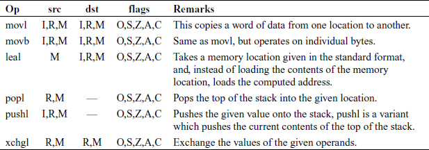
Data Transfer Instructions
These instructions are mostly used for moving data from one place to another. They are given in Table 12.1.
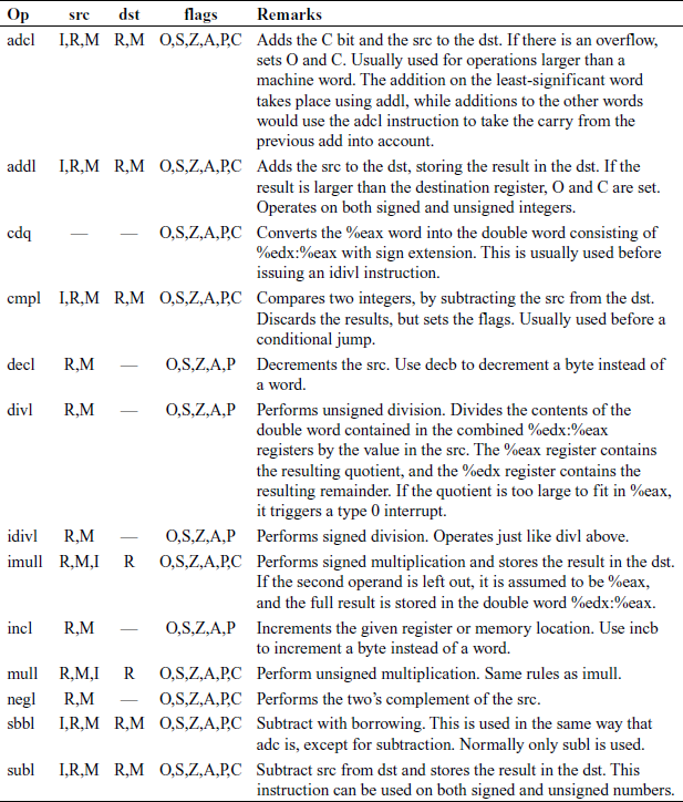
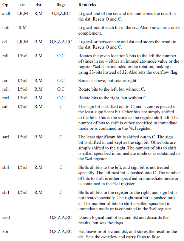
Integer Instructions
These are the basic computing instructions that operate on signed or unsigned integers, given in Table 12.2. The logic instructions are given in Table 12.3. The flow control instructions are given in Table 12.4.

Condition codes are:
- [n]a[e] – above (unsigned greater than). An n can be added for not and an e can be added for “or equal to”
- [n]b[e] – below (unsigned less than)
- [n]e – equal to
- [n]z – zero
- [n]g[e] – greater than (signed comparison)
- [n]I[e] – less than (signed comparison)
- [n]c – carry flag set
- [n]o – overflow flag set
- [n]p – parity flag set
- [n]s – sign flag set
- ecxz – %ecx is zero
12.4.2 Assembler Directives
These are instructions to the assembler and linker, instead of instructions to the processor. The most essential of them are given in Table 12.5.
Table 12.5 Assembler directives
| Op | Operands | Remarks |
|---|---|---|
| .ascii | Quoted string | Takes the given quoted string and converts it into byte data. |
| .byte | Values | Takes a comma-separated list of values and inserts them right there in the program as data. |
| .endr | — | Ends a repeating section defined with .rept. |
| .equ | Label, value | Sets the given label equivalent to the given value. The value can be a number, a character or a constant expression that evaluates to a number or character. From that point on, use of the label will be substituted for the given value. |
| .globl | Label | Sets the given label as global, meaning that it can be used from separately compiled object files. |
| .include | File | Includes the given file just as if it were typed in right there. |
| .lcomm | Symbol, size | This is used in the .bss section to specify storage that should be allocated when the program is executed. Defines the symbol with the address where the storage will be located, and makes sure that it is the given number of bytes long. |
| .long | Values | Takes a sequence of numbers separated by commas, and inserts those numbers as 4-byte words right where they are in the program. |
| .rept | Count | Repeats everything between this directive and the .endr directives the number of times specified. |
| .section | Section name | Switches the section that is being worked on. Common sections include .text (for code), .data (for data embedded in the program itself) and .bss (for uninitialized global data). |
| .type | Symbol, ©function | Tells the linker that the given symbol is a function. |
12.4.3 Floating-point Instructions
The x86 architecture implements the IEEE-754 standard. The IEEE-754 32-bit precision format divides the 32-bit value into three different sections:
Sign size = 1-bit, bit-range: 31–31;
Biased exponent size = 8-bits, bit-range: 30–23; minimum value = –126 and maximum value = 127;
Mantissa size = 23-bits, bit-range: 22–0.
The mantissa expresses a fraction of the form 1.x where x is expressed by the mantissa section. Let s be the sign bit, be be the biased exponent and mi, i ∈ {1, 2, …, 23} be the mantissa, then the value of most of the IEEE-754 encoded floats is given by:
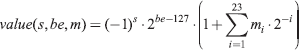
There are certain special cases for invalid numbers, infinity and zero, etc. There are positive and negative infinities, positive and negative NaNs (Not-a-Numbers).
The special cases are:
- if exponent is 0 and fraction is 0, the number is ±0 (depending on the sign bit),
- if exponent = 255 and fraction is 0, the number is ±infinity (again depending on the sign bit), and
- if exponent = 255 and fraction is not 0, the number being represented is not a number (NaN).
Some sample values (in hex) are: positive zero: 00 00 00 00, negative zero: 80 00 00 00, positive 1: 3F 80 00 00, negative 1: BF 80 00 00.
There are five possible exceptions with floating-point numbers:
- Invalid operation (e.g., square root of a negative number)
- Division by zero
- Overflow (a result is too large to be represented correctly)
- Underflow (a result is very small (outside the normal range) and is inexact)
- Inexact
The FPU contains 8 80-bit stack elements called %st(0), %st(1), …, %st(7). They are implemented as a stack so that %st(0) always refers to the top element, %st(1) to the one below the top, etc. This makes it quite tricky to use.
FPU code is rather fragile and often hard to read. It is strongly recommended that you read a good instruction set reference simultaneously when you are working with FPU code. We take some easy examples to see how the FPU stack works. Here is the state of the FPU at the beginning of the program:
%st(0) undefined
%st(1) undefined
%st(2) to %st(7) undefined
All FPU instructions have the f– prefix. If an instruction has a –p suffix it means that it pops the top element off the stack at the end of its execution. We are going to execute the following instructions on the FPU now:
#push one on top of the stack
  fld1
#push zero on top of the stack
  fldz
#add them up and store the result in \%st(0)
  fadd %st(1), %st(0)
#add the top two elements up and store the result in \%st(1),
#pop the stack
  faddp %st(0), %st(1)
Let us go through the changes in the FPU stack, instruction by instruction. Changes to registers are shown in italics. We start with fld1, which puts constant 1.0 on the stack:
%st(0) 1.0
%st(1) undefined
%st(2) to %st(7) undefined
Next, fldz adds another constant (0) to the top of the stack:
%st(0) 0.0
%st(1) 1.0
%st(2) to %st(7) undefined
Perform an addition %st(0) = %st(0) + %st(1) with the specified stack elements using fadd:
%st(0) 1.0
%st(1) 1.0
%st(2) to %st(7) undefined
The next instruction faddp does two things. The FPU performs the addition %st(1) = %st(1) + %st(0); using faddp,
%st(0) 1.0
%st(1) 2.0
%st(2) to %st(7) undefined
and then discards the top element after the addition (the p suffix):
%st(0) 2.0
%st(1) to %st(7) undefined
The data types handled by the FPU are 16–, 32– and 64–bit integers, and single (32–bit), double (64–bit) and extended (80–bit) precision floating point. Each supported type has an instruction mnemonic suffix and a constructor associated with it. Instruction mnemonic suffixes specify the operand's data type. Constructors build these data types into memory.
- Floating-point constructors are ‘.float’ or ‘.single’, ‘.double’ and ‘.tfloat’ for 32-, 64- and 80-bit formats. These correspond to instruction mnemonic suffixes ‘s’, ‘l’ and ‘t’. ‘t’ stands for 80-bit (10-byte) real. The only FPU support for this format via the ‘fldt’ (load 80-bit real to stack top) and ‘fstpt’ (store 80-bit real and pop stack) instructions.
- Integer constructors are ‘.word’, ‘.long’ or ‘.int’ and ‘.quad’ for the 16-, 32- and 64-bit integer formats. The corresponding instruction mnemonic suffixes are ‘s’ (single), ‘l’ (long) and ‘q’ (quad). As with the 80-bit real format, the 64-bit ‘q’ format is only present in the ‘fildq’ (load quad integer to stack top) and ‘fistpq’ (store quad integer and pop stack) instructions.
- Register to register operations should not use instruction mnemonic suffixes, ‘fstl %st, %st(1)’ will give a warning and be assembled as if you wrote ‘fst %st, %st(1)’, since all register to register operations use 80-bit floating-point operands. (Contrast this with ‘fstl %st, mem’, which converts ‘%st’ from 80- to 64-bit floating-point format, then stores the result in the 4 byte-location ‘mem’.)
Remember that the floating-point registers are 80-bit wide, while the x86 integer registers are 32-bit wide. This means that the data transfer to and from the FPU registers should always be done via the FPU load and store instructions. We give here a small example of FPU manipulations, using the standard C library printf() function to display the results. The name of the test program file is test11asm.S. This example will also illustrate how to use the C library with our own assembly language programs, mainly to do the input/output.
.section .data
fmt:     .asciz ″number = %f
″
newline: .asciz ″
″
number:  .float   123.456

.section .text
         .globl _start
_start:
          pushl %ebp
          movl  %esp, %ebp
          flds  number
          leal  –8(%esp), %esp
          fstpl (%esp)
          pushl $fmt
          call  printf
          addl  $8, %esp
          fld1
          fldz
          fadd  %st(1), %st(0)
          faddp %st(0), %st(1)
          leal  –8(%esp), %esp
          fstpl (%esp)
          pushl $fmt
          call  printf
          addl  $8, %esp
_exit:
   movl $1, %eax
   movl $0, %ebx
   int  $0x80
This program was processed by:
as –o test11asm.o test11asm.S
ld ––dynamic–linker /lib/ld–linux.so.2 –lc –o test11asm test11asm.o
and when executed, it printed:
number = 123.456001
number = 2.000000
The x86 FPU has built-in instructions for computing the usual mathematical functions such as square-root, logarithm, exponential, sine, cosine, etc. We shall use them as built-in functions in the miniC language.