Chapter 4:
Conforming a Workprint
Not all digital films are spared the blade. Although some can spend the entire phase of post production in the digital realm, most films can’t escape the need for being screened in their natural environment: the theater. Rightly so, because one can never know what might be encountered until a film is displayed in the environment in which it was meant to be shown.
Not long ago I viewed a documentary about the building of Boeing’s 777 aircraft. The engineers found a way to test the fitting of parts and structure of the plane in a simulated virtual mode. Nothing was ever manufactured, machined, or tested until it was first created and tested in a computer. Of course, eventually all parts were crafted and tested, and in the end, the plane had to be as airworthy in the real world as it was on the computer.
Conforming a workprint is like that. In the world of digital NLEs, the film is seen as it “will be”. But one can only truly be sure of its effect when it is built in its final intended medium.
I’ve attended plenty of screenings of films that skipped conforming a workprint or bypassed screening in a larger format, like a projection TV. The final digital cut was output verbatim to a cut list and sent directly to the negative cutter. More often than not, there are problems with these films. Conforming a workprint gives editors an opportunity to correct problems. What is seen on the small screen doesn’t always translate well to a theater, and vice versa. If a film were an aircraft, conforming a workprint would be its test flight.
The conforming process helps the people who handle the film later. In particular, it gives a road map for the negative cutter. Without a workprint, the neg cutter is working strictly with a list full of numbers. If any problems exist in the list, they might be discovered when it is too late. A workprint gives a direct physical frame-to-frame reference of the cut.
Before the process of actually printing and cutting film begins, the editor needs to prepare the digital cut to match the characteristics of film. This can be a tedious process, but it also makes the difference between a well-done screening and a disastrous calamity of miscued reels. There are three steps that need to be taken.
Balance the cut into 1,000 foot reels
Add SMPTE leader
Create a pull list and an assemble list
Creating and Balancing the Reels
In the real world, 1,000 feet is the standard maximum length for any single reel of film intended for screening. The length of each individual reel can vary, depending on where the best cut point or ending is located. Normally, the best cut point is between scenes. At the end of each reel, another continuous second of the last scene on the reel is added after the last frame of action (LFOA). This LFOA (also called the EOR, end of reel, or LFOP, last frame of picture) is where the reel change should be made. The extra second is used for human error on the changeover between projectors. Some people, particularly those better versed in video than film, are shocked to learn that projection isn’t a computerized science. More about that later.
Balancing can be tricky. The length of the reels will vary, but they should never be less than 700 feet nor more than 1,000 feet. When counting the footage, be sure to include the length of the SMPTE leader on each reel. It is preferable to keep the reel length longer than 800 feet, because anything less could lead to calamity in the projection room. An 800-foot roll of 35mm film is just under nine minutes long, and the projectionist needs time to load each reel.
There can be issues with measuring the lengths of film. Using an NLE that doesn’t keep track of running footage during an edit necessitates the use of either a footage calculator or a chart (see Appendix A: Time/Footage Conversions). There is also a handy device used in many cutting rooms called a Reddy-Eddy. This device calculates footage and running time on a circular graph.
I use a footage calculator on my computer, but the length of reels can also be verified by some simple calculating.
For example, a reel of a 16mm feature ends at 23:40. The first step would be to translate everything into seconds. So take the number of minutes, multiply them by 60, and add them to the leftover seconds, like this:
(23 * 60) + 40 = 1,420 seconds
The next step is to take the total number of seconds and multiply them by 24 to determine the number of frames, like so:
1,420 * 24 = 34,080 frames
Finally, take the number of frames and divide them by the number of frames in a foot of film. In 16mm, this is normally 40 frames per foot. With 35mm, it would be 16 frames per foot. So the end result is:
34080/40 = 852 feet
852 feet is the length of the reel.
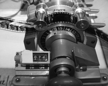
Figure 4.1 Measuring footage on the bench.
Adding SMPTE Leader on the NLE
Once manageable, balanced cut points for each reel are located, and separate sequences are made of the reels. In most NLEs it is very simple to mark the beginning and end frame and then drag them back as subcuts into a reel bin. After the subcuts for all of the reels are created, add SMPTE leader.
SMPTE leader can be added later when the reels are conformed and built, but I like to do it in the NLE first, because it’s easier to calculate the length of each reel and create a continuity report, which documents the running time of each reel, before the pull list is created. The further I get ahead in my paperwork, the happier I am.
In order to create the complete reel in an NLE, SMPTE leader (on videotape) or a Quicktime movie of SMPTE leader is necessary. Once the SMPTE leader has been digitized, place it at the head of each reel in the NLE. The first frame should be the frame that has “Picture Start” on it. After the 2 frame, there should be 59 video frames of black, then the cut picture should begin.
Add one frame of 1000 Hz tone on the 2 frame. Like most facilities, we have a tone generator at Film Camp, but a 1000 Hz sound file can be imported into the NLE and cut on the 2 frame. This is called the 2 pop or sync pop.
Once the SMPTE has been added to all of the reels, output a cut list to go to the lab. The lab will create a roll of all of the scenes in the film. The next job is to cut them up and assemble them.
The Pull List
The pull list is a type of cut list that tells the person conforming exactly which shots to pull from an OCN or workprint. When a pull list is created, it lists the cuts by cam roll. That way, the person creating the workprint can pull everything needed from each roll, then print it. A pull list is the film world’s equivalent to a video on-line C-mode editing list. If a standard assemble cut list, which lists the cuts chronologically from beginning to end, is used, the person conforming the film would have to go back and forth between cam rolls. This is not only unnecessary, but tedious.
Screenings can be pretty nervous gatherings, and every film cutter has an awful story to tell about a screening gone bad. Suffice it to say that accuracy is the key here. Put together a solid pull list for each reel and double check it. Some editors like to add extra frames called frame handles to each cut in the list. This can “force” them to double check the numbers when they assemble the workprint.
Every pull list should include
Lab roll number
Cam roll number
Scene number
Key number in
Key number out
Duration (feet + frames)
Anything else is optional. For most matchback and 24 fps NLE applications, master time code, comments, original clip names, and time code durations can be placed in the pull list as well. It’s handy to have the time code durations to check against the digital cut, but not mandatory. After a pull list is made and checked, send it to the lab.
The lab can and will make mistakes from time to time. Once the workprint is received from the lab, check it against the pull list to make sure everything is there.
Once the workprint is made, it’s time to conform. If the editor absolutely feels uncomfortable with physically cutting film for the first time, he or she can always hire an experienced assistant to do it for them. But if someone else does the cutting, it’s important to watch carefully and ask lots of questions.
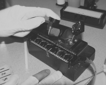
Figure 4.2 Cutting on the frameline
Most film editors love touching film. But that’s not necessarily true for those of us who work mostly with video. At first, one might feel overcautious. In this case, fear is good. Make sure the print is conformed right the first time, or it will be tough putting it back together.
The first step is to separate each shot in the pull list and hang it in a bin. Handle the workprint carefully and make sure it stays put on its bin hook. It’s very easy to scratch work print. Normally a director might expect the print to be pretty scuffed up by the time it makes it to a screening, but when used in conjunction with an NLE, expectations run higher, as the workprint is new.
On the edit bench, load the first roll of workprint on the left-hand side, shiny side down, emulsion up. Zip past the leader and find the first frame of print. Check the key number against the pull list. To count frames, find the nearest key number. There is a small dot in between the key number and key code (bar code) on the edge of the film next to the sprocket holes. This is the zero frame reference mark (see Figure 4.3). The zero frame reference mark lies next to the “Zero” frame. From that mark, count frames. Each corresponding frame beyond the mark is +1, +2 and so on. Find the proper frame and insert it into the splicer. The cut should be made along the frameline before the frame. Once the film is aligned into the sprockets of the splicer and it is verified that the blade will fall on the frameline, cut it.
Figure 4.3 The zero frame reference mark next to the key number
Pull the first frame of the clip to the takeup reel on the right side of the bench and zip ahead to the last frame of the clip according to the pull list. Remember to count forward from the key number. Be sure to make the cut after the correct frame.
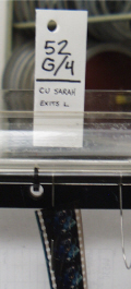
As each clip is cut out of the roll of workprint, place a trim tab on it and hang it in the bin on a pin. A trim tab contains information relating to each clip. There are two types of trim tabs: rectangular (West Coast) and cross shaped (East Coast). The trim tabs contain information helpful in identifying the clip. Typically, a trim tab can contain key numbers, in and out; a description of the shot (i.e., “LS- Gilligan and Mary Ann”); and scene and take number.
As each clip is cut, hang it in the bin left to right to match the order in which the clips will be conformed, using an assemble list as a guide. Hang each shot on a separate pin. Once all of the workprint is hung in the bin, the fun really begins.
Splicing It Together
Before splicing the reels together, the first task is to output an assemble list for each reel. If SMPTE leader was added in the NLE sequence, it will be the first cut. From there, take each clip in the list and add it to the reel. The cuts in the assemble list should be in chronological order according to the original digital version of the reel. A splicer and plenty of tape are needed for this task. For a screening, I highly recommend that both sides of the splice are taped. If the film is being screened on a flatbed or upright, taping one side should be enough.
Eventually, every editor associated with film will need to learn how to properly use a splicer. It takes time, patience, and a little manual dexterity. Explaining how to splice takes little effort: just cut, tape, and tamp it down. But the best method of learning how to use a splicer is to work with someone who has used it before. Once the process is learned, splicing is like riding a bike.
There are many different splicers on the market. One of the most popular is the Rivas. Rivas splicers, also known as butt splicers, have sprockets for alignment, straight and slanted channel cutting guides, two tape dispensers, a large blade, and a tamper for securing the tape (see Figure 4.5).
Figure 4.5 A Rivas Splicer
There are two types of tape: clear and white. White tape is used for sound, clear for picture. Pictures are cut straight across the frameline. Sound is cut diagonally.
Film reels use three types of leader: clear leader for head and tail, picture leader for information at head and tail, and SMPTE leader at the beginning just before the picture starts. To begin, some clear leader is needed. It takes 10 to 12 feet of leader to thread a projector. The clear leader takes a beating during rewinding, so several feet won’t hurt. After the clear leader, add some picture leader. On the picture leader, write information about the reel with a black permanent marker. For example:
“Good Taste Takes a Holiday” Cut Work Pix R-1 Pix Heads.
A consistent rule is that picture tracks are marked with black markers and sound is marked with red.
After the picture leader, splice in the SMPTE leader. Order this from the lab if necessary. As splicing tape is added to each cut, make sure that the tamper is pressed hard against the tape surface to ensure a firm splice.
From here, begin the picture conform. Follow the assemble list from beginning to end for each reel. In the original digital cut, 24 frames should have been remaining at the end for a changeover between reels. After the changeover, attach a picture tail leader and several feet of clear leader.
Opticals
When blending any two film elements together or manipulating the frame of a film, such as in a dissolve, a matte, a fade or a blow-up of the frame, an optical is required. Opticals are almost never created for screenings. If there are any opticals in the cut list, it is necessary to add leader for the duration of those opticals. Some editors use “scene missing” leader for these sections. Others attach white leader. But be sure that the leader is the correct duration for the optical in order to keep the reel in sync with sound.
Another method for dealing with opticals involves the cut list. If the option of showing dissolves and wipes as cuts is selected, the two shots can be spliced together and the transition can be drawn with a grease pencil. With this method, it clearly shows that there is a transition, but it also doesn’t interrupt the flow of the film as it is screened.
Marking Workprint for Motor Start and Changeover
Every motion picture contains two marks at the end of the reel. These marks can be seen in the upper right-hand corner of the picture. The first is called a motor start cue. This signals the projectionist to start the motor (but not the projector lamp and sound head) for the next reel. The second is a changeover cue. This signals the projectionist to switch between projectors to the next reel of film.
Many modern theaters have huge platters where the entire film is laid and projected from beginning to end. The projectionist hits one button and the film begins. But this isn’t true for all theaters and most screening rooms. These rooms use two projectors in the booth and switch projectors during reel changes or changeovers. In order to let the projectionist know when to change reels, a visual cue is given in the picture on the screen.
Some assistants use small, sticky, white dots and others mark the workprint with the slash of a grease pencil. For a screening, either is fine. Each cue consists of four marked frames. It’s important that the marks made are visible on the screen, so don’t forget to mark it within the aspect area of the film.
The motor cue begins 200 frames before the last frame of action (LFOA). Beginning at that point, mark four consecutive frames, again considering the screening aspect of the film.
The changeover cue occurs one second before the LFOA. Remember, an additional second of picture is necessary beyond the LFOA for human error. Mark four consecutive frames from the one-second point.
When it comes to NLEs, sound is relatively simple to output. Sound can be transferred directly from NLE to time code DAT or other time coded source. In fact, time coded source isn’t really necessary, so long as the 2 pop is inserted at the correct point.
Some editors take a little time to create a rough mix for screenings. In betterfunded films, the rough sound would go to the sound department for a temp mix. Either way, anything that will enhance the screening process is considered good.
Sound can be transferred digitally direct from NLE to a tape source. Be sure to transfer at the proper sampling rate. If there is access to direct digital output from the NLE and input to the source, use it. The fidelity and clarity make a big difference at screenings.
From the taped output, the sound will have to be transferred to mag stock. But before it is transferred, there is one small issue to resolve. If the NLE cut picture and sound are at a true 24fps rate, it’s fine. But if matchback software was used and the pulldown speed wasn’t corrected, the difference in speed will need to be resolved.
Chapter 2 discusses slowing down telecine to match the NTSC frame rate of 29.97. To match the video frame rate, film is actually transferred via telecine at 23.976 fps instead of 24. As a result, because the speed of sound on matchback projects wasn’t properly adjusted with an audio coprocessor, the resulting output will run at 23.976, not 24. This means that the sound is running about .01% too slow. When the sound output is sent out for a mag stock transfer, be sure to make a note to the lab that the sound needs to be sped up .01% during transfer.
After the sound is transferred, there is the final task of building the sound reels. Because the mag in is one piece, there will be no need for internal edits. But clear leader and marked sound leader need to be added at head and tail of each reel. Use the same pattern that was shown for the picture leader, but use a red marker instead of black. The 2 pop needs to be marked with a red marker so that the projectionist can set it up appropriately to ensure that sound will run in sync with picture (see Figure 4.6).
Figure 4.6 Marking the 2 pop in the sync blocks
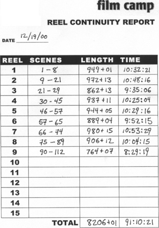
Continuity Reports
Once the reels are built, it’s time to make a reel breakdown or continuity report. The report shows the scene numbers on each reel, footage length and time. At the bottom, there is space for total footage and duration.