Chapter 1
Introduction
The coming of age of electro-optical instrumentation dates back to a few years after the invention of the laser, that is, during the mid 1960s. The enormous potential of lasers in measurements was soon recognized by the scientific community as one capable of providing new approaches with unparalleled performances. Plenty of successful examples of several instruments and sensors started to appear in the 1970s, including gyroscopes, laser interferometers, pulsed telemeters, and laser Doppler velocimeters. These instruments were at first just bright scientific ideas, but, after several years of research and development, they grew up to industrial products of great success.
Initially, military applications provided a big push to the research and development effort, and, in the system balance, the laser played the role of the enabling component. After a few decades, parallel with the growth of a civil application market, electro-optical instrumentation became to stand on its own feet.
The focus of attention then moved from the source to the philosophy of measurement, thus boosting the synergy of optics and electronics and merging the new technology in the frame of measurement science.
1.1 Looking Back to Milestones
The album of successes of electro-optical instrumentation soon became very rich and astonishing.
About telemeters, we may recall the famous LUnar Ranging Experiment (LURE) carried out in 1969 (Fig.1-1) when the astronauts of Apollo 11 brought on the moon a 1-m by 1-m array of corner-cubes [1].
Several telescopes of astronomical observatories on earth aimed their own ruby laser, Q-switched pulsed beam on the array. The task was difficult, because the target was invisible and only its lunar coordinates were available. Three out of five telescopes succeeded in hitting the target and getting the very small (about 10 photons) return. The pulse delay, or time-of-flight (about 2 seconds), was measured with nanosecond resolution, thus sampling the 384,000-kilometer distance to about 30-centimeter.
This was not just a mere big-science exhibition, as this early laser ranging experiment was the forerunner of the modern earth-to-satellite telemeter network. Now long-distance measurement by laser telemeters is an established, powerful tool for geodesy survey.
Fig.1-1 The LURE experiment in 1969 set the record of long-distance pulse telemetry. The baseline was the 384,000-km earth-to-moon distance.

The experiment also opened the way to airborne telemeters and altimeters (Fig.1-2), based mainly on the Nd:YAG Q-switched laser and occasionally on CO2 lasers for better transmission through haze and fog. The most recent versions employ compact semiconductor-laser telemeters and fit in the headlight compartment of a car (Fig.1-3) [2].
This telemeter is now sold as a standard product of automotive anticollision systems. It fosters next years’ automatic–guide systems, which is not a dream of science fiction anymore, but a technical reality being actively pursued.
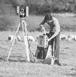
The sine-wave-modulated diode-laser telemeter introduced in the early 1970s is now an instrument widespread in construction works and marks the retirement of the old theodolite and associated set of rulers (Fig.1-4) [3].
As a device directly evolved from the early concept, the topographic telemeter provides 1-cm accuracy over several hundred- to thousand-meter distance and accounts for a healthy $200 million per year market segment.
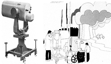
Fig.1-2 Pulsed telemeters (based on Q-switched solid-state lasers) have been routinely mounted aboard military aircraft since the 1970s …

Fig.1-3 … and their compact variants (based on semiconductor diode lasers) entered the automotive market in recent years, as the sensor of anti-collision systems [2]. They are likely to become the key of future automatic-drive systems (photo courtesy of CRF-Fiat, Turin).

Fig.1-4 Meanwhile, in the early 1970s [3], sine-wave modulated telemeters started replacing the old theodolite in civil engineering applications. Distance measurement is now carried out instantly in the field on ranges up to several hundred meters and cm resolution.
The LURE experiment sensation was renewed and amplified recently by the Mars Orbiter Laser Altimeter (MOLA) flown aboard the Mars Global Surveyor in 1997, which orbited the red planet for over a year to collect height data on the Mars surface.
The MOLA altimeter sent the amazing map in Fig.1-5 back to earth. In this map, pixels are 100-m×100-m wide, and their relative height has been mapped with a 10-m accuracy [4] from the average 400-km distance from the planet surface [5]. The telemeter aboard the Mars Global Surveyor uses a diode-laser pumped Cr,Nd:YAG laser that operates in Q-switching regime as the source and supplies 8-nanosecond (ns) pulses at 10-Hertz (Hz) repetition rate. The receiver is a 50-cm diameter telescope ending on a Si-avalanche photodiode detector and includes a 2-nanometer (nm) band pass filter to reject solar background.
Similar to planetary telemeters, a number of Laser Ranger Observatories (LRO) have been built around the world to target geodetic satellites in earth orbit. One of these, the Matera LRO [6], reaches 25-ps of timing accuracy, or approximately 3 millimeter of range accuracy.
Another version of the basic telemetry scheme is provided by the Laser Identification, Detection, and Ranging (LIDAR, see Sect.3.5). This instrument is again a pulsed telemeter, but has a λ-tunable laser as the source. By analyzing the echoes collected from the atmosphere, according to different conceptual schemes (DIAL, CARS, etc.), pollutant concentrations can be measured down to part-per-billion (ppb) concentration with distance-resolved plots of the pollutant concentration (Fig.1-6).
Fig.1-5 Map of Mars as provided by the MOLA orbiting telemeter (1998). Pixels are 100 m in size, and their height is measured to a 10-m accuracy by the orbiting telemeter (courtesy of MOLA Science Team).

Fig.1-6 The LIDAR is a pulsed telemeter, but with a λ-tunable laser as the source. Echoes from the atmosphere at different wavelengths allow measuring pollutants down to ppb concentration and get distance-resolved plots (from [7], courtesy of Ferranti UK).
The gyroscope is another big success, both scientific and industrial, of electro-optical instrumentation. The laser gyroscope concept was demonstrated as early as 1962, just one year after the discovery of the He-Ne laser. The seminal experiment was carried out in the laboratories of Sperry Corp.[8], with a 4-arms He-Ne, 1-m by side, square ring configuration capable of detecting the earth rotation rate (15 degree/hour). See Fig.1-7. From this encouraging start, the way to a commercial gyroscope suitable for field deployment was then long and full of obstacles, like the locking effect, which was very hard to overcome.
Fig.1-7 Early demonstration of the Sagnac effect in a square cavity He-Ne laser by Macek of Sperry Corp. in 1962 (from [9], by courtesy of the Institute of Electrical and Electronic Engineers [IEEE]).

Fig.1-8 A modern 4-inch side ring laser gyro (RLG) is the heart of the Iinertial Navigation Units (INUs) of today’s airliners (from [9], by courtesy of IEEE).

Only after a decade of worldwide research efforts by the scientific community, clever conceptual solutions and improved technology finally evolved, which led to the modern top-class RLG with the amazing accuracy of 0.001°/h. This device (Fig.1-8) has been used in all newly fabricated airliners since the 1980s. It is the heart of modern Inertial Navigation Units (INUs), electronics box about 10 inches on a side that costs $1.5 million. The INU is capable of telling the actual position of the aircraft with 1-mile accuracy after a few hours of flight.
The gyro story did not come to an end, however. In 1978, by taking advantage of the newly developed single-mode fibers, the Fiber Optics Gyroscope (FOG) was proposed, and the quest restarted with another technology. The aim was to produce a medium-class light, cheap, and more reliable device especially for space applications.
Again, about a decade of efforts has been necessary to cure a series of small idiosyncrasies of the new approach. Units were finally ready in the 1990s (Fig.1-9) for use as a reference aboard telecommunication satellites as an attitude system as well as for military applications. Because of its low cost, the FOG was also initially used in the automotive industry to demonstrate the car navigation concept (Fig.1-10). Today, it has become clear that, despite the attempts to squeeze the production cost, the FOG is too complex to meet the desired target price.
Because the automotive market is very strong, a last generation effort of the electro-optical gyroscope is being pursued using the Micro-Optical-Electro-Mechanical System (MOEMS) technology [10]. Once more, it is likely that we will record a new breakthrough in gyro in the next years.
Fig.1-9 A 3-inch diameter fiber optics gyroscope (right) and its printed circuit board for signal processing (left) (model FOG-1B introduced by SEL Alcatel in 1990).

Fig.1-10 The gyroscope has opened the way to car navigators and modern adaptive cruise control (by courtesy of Magneti Marelli Sistemi Elettronici, Torino).

Interferometry is another big chapter in electro-optical instrumentation. As soon as the first He-Ne lasers were frequency-stabilized in the mid-1960s, many scientific as well as industrial applications were created, taking advantage of the unprecedented coherence length made available by this source. Well-known examples, and a huge commercial success, are the so-called laser interferometer and Doppler velocimeter. These soon penetrated and captured the markets of mechanical metrology and machine-tool calibration and the fluidics and anemometry engineering segments, respectively. These instruments sell at levels of 10,000 units per year and by themselves would justify a place for electro-optical instrumentation.
In addition, the synergy of optics and electronics has pushed the field of interferometry well beyond the fringe performance of the classical eighteenth century optics. Pico-meters or atto-meters are well resolved in displacement, as well as 10-9 strains in relative Δl/l variation. After the early detection of earth-crust tides (in the 1960s, at a 10-9 strain), a big scientific enterprise is being completed in these years, namely the interferometer detection of gravitational waves coming from remote galaxies and massive collapsing stars.
A number of teams are developing gravitational antennas around the world (in the United States, Europe and Japan) under the names of Laser Interferometer Gravitational Observatory (LIGO) [11], Laser Interferometer Gravitational Antenna (LIGA), etc. (see Fig.1-11). Recently, a proposal to build a 5-million-km arm space interferometer is under study [12]. These interferometers push the resolution to unprecedented (10-20m in LIGO), yet theoretically achievable, limits (as set by the quantum noise). The LIGO instrument may soon become a new window for probing the cosmos that will be comparable in importance and observational results, perhaps, with the advent of the radio telescope.
Fig.1-11 The LIGO interferometer has 2-km arms (top: the facility; bottom left: the optical layout). The instrument should be able to detect the gravitational collapse of a star into a black hole a Megaparsec away. To rule out spurious pulses due to earth perturbations, two interferometers located 3000-km apart will operate in coincidence (bottom right). Photos reprinted by courtesy of Caltech/LIGO.

Another ambitious project involving interferometry is the Terrestial Planet Finder (TPF), which was recommended by the Astrophysics Survey Committee. The instrument will comprise four 3.5-m telescope mirrors placed in space a few km apart and should be able to detect earth-size planets around stars up to 50 light-years away.
The initial effort to validate the concept is the Space Interferometer Mission (SIM) scheduled for launch in 2009. It consists of an optical stellar interferometer with 10-m baseline, and will be capable of measuring angular coordinates of stars with approximately 50 pico-radian accuracy.
The test facility of the instrument is a 10-pm resolution interferometer [13] that operates on an approximately 10-m arm length.
In summary, just from the few examples previously reported, we may conclude that the field of electro-optical instrumentation has been very exciting since its inception.
Though only a few decades old, electro-optical instrumentation has already achieved remarkable scientific and technical successes and has proven the advantages of a synergy and cross-fertilization of optics and electronics.
A healthy field not licked by the bubble-technology syndrome, electro-optical instrumentation will continue to grow in ideas and achievements. In the years to come, this field will certainly continue to offer significant potential to researchers and engineers from the point of view of advancement in science, as well as of engineering development of new products.
References
[1] C.O. Alley et al., “The LURE Experiment: Preliminary Results”, Science, vol.167 (1970), p.368.
[2] L. Ampane, E. Balocco, E. Borrello, and G. Innocenti, “Laser Telemetry for Automotive Applications”, in Proceedings of LEOS Conference ODIMAP II, edited by S. Donati, Pavia, 20-22 May 1999, pp.179-189.
[3] AGA Geodimeter model 710, Publication 571.30006 2k8.71 (1971).
[4] M.T. Zuber and D.E. Smith, “The Mars Orbserver Laser Altimeter Investigation”, J. Geophys. Res., vol.97 (1992), pp.7781-7797.
[5] D.E. Smith and M.T. Zuber, “The MOLA Investigation of the Shape and Topography of Mars”, Proceedings of LEOS Conference ODIMAP III, edited by S. Donati, Pavia, 20-22 September 2001, pp.1-4.
[6] G. Bianco and M.D. Selden, “The Matera Ranging Observatory”, in Proceedings of LEOS Conference ODIMAP II, edited by S. Donati, Pavia, 20-22 May 1999, pp.253-260.
[7] Ferranti 700 Series Lidar System, Publication DDF/524/675 (June 1975).
[8] W.M. Macek and D.I.M. Davis, “Rotation Rate Sensing with a Travelling wave Laser”, Appl. Phys. Lett., vol.2 (1963), p.67-68.
[9] G.J. Martin, “Gyroscopes May Cease Spinning”, IEEE Spectrum, vol.23 (October 1986), pp.48-53.
[10] E.A. Brez, “Technology 2000: Transportation”, IEEE Spectrum, vol.37 (January 2000), pp.91-96.
[11] B.C. Barish and R. Weiss, “LIGO and the Detection of Gravitational Waves”, Physics Today (Oct.1999), pp.44-50.
[12] J. Riordon, “An Early Look at LISA”, Sky and Telescope (October 2000), pp.46-47.
[13] P.G. Halverson et al., “Characterization of Picometer Repeatability Displacement Metrology Gauges”, in Proceedings of LEOS Conference ODIMAP III, edited by S. Donati, Pavia, 20-22 September 2001, pp.63-68; see also huey.jpl.nasa.gov.