▶ 5.7 Input/Output and File System Software
We looked briefly at the standard features of modern operating systems: processes, memory management, input/output, and files (see Section 2.2.2). Here is how the operating system provides the last two:
■ The operating system provides a simple and uniform way for programs to use I/O devices or files.
■ When a program performs an operation on a file, the file system software transforms it into simple, standard I/O operations performed directly on the hard drive or other storage volume.
■ The I/O system converts these standard operations into the specific actions required by individual I/O devices.
As systems have evolved in complexity, I/O has likewise evolved. Originally, systems focused on reading and writing streams of text that programs processed sequentially, 1 byte at a time, or one line at a time. Hard drives, when available at all, were tiny by modern standards.
Today, the I/O system must handle massive hard drives while instantly responding to keystrokes and flicks of the mouse. A practical modern system must be able to integrate a broad range of currently available I/O products, including hundreds of different printers, keyboards, mice, hard drives, USB drives, cell phones, Bluetooth devices, and other things. Moreover, the system also must be flexible enough to be able to integrate newer devices as soon as they appear.
Device Independence
Programming is a difficult task. I/O devices have always posed the biggest challenge. In the early days of computing, every program was custom written to work with the specific hard drives, printers, and other I/O devices on the programmer’s computer. The programmer often had to rewrite parts of a program when new I/O devices appeared.
Device independence was an important feature of early operating systems. This provided programmers with a standard, uniform interface for programming I/O devices. The operating system provided specialized programs—the device drivers—that converted standard I/O requests into device-specific requests.
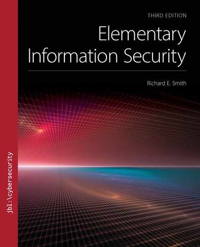
The Hourglass
The I/O system tries to provide maximum flexibility for applications and for I/O devices. This yields the hourglass design shown in FIGURE 5.17. The broad range of application program requirements are fulfilled by the I/O and file systems. The broad range of I/O device interfaces are mapped to the system’s device driver interface.
FIGURE 5.17 “Hourglass” structure of the I/O and file system.
This flexibility is demanded by the computing industry. Computer systems would be much simpler to build if everyone used the same browser software, or if all hard drive hardware worked exactly the same. The marketplace doesn’t work that way in practice. Vendors flourish by providing features that competitors lack. Hardware vendors add new features and operating systems must accommodate these features. Likewise, application developers want to find new ways to use existing computing resources, and operating systems must be flexible enough to meet their needs.
File System Software
The operating system distinguishes between the file system software and the I/O system. The file system software handles the structure and organization of files on hard drives. The I/O system provides a uniform interface for performing basic I/O operations. In practice, the phrase file system may refer to a set of file storage formats or it may refer to the file system software that manages a particular format.
When we connect a removable drive to a computer, the operating system automatically tries to use the drive for storing and retrieving files. The software reads the boot blocks and volume labels from the drive to try to recognize the file format. If the system doesn’t recognize the file format, it may ask for help. Typically, the system asks the user if the drive should be ignored, ejected, or reformatted with a recognizable file system.
If the system recognizes the file format, it tries to mount the file system. This connects the file system to the operating system’s file software. Once mounted, we may use the user interface to navigate through directories and folders stored on the drive. The file system software saves information about the file system in RAM while it is mounted.
When the system mounts a drive, it takes exclusive control of it. Other programs, run either by users or administrators, are supposed to use the file system software for all accesses to that drive.
If a program tries to read or write to the drive directly, instead of using the file system software, there is a risk that the file system might read or write the same data block for a different purpose. This is a concurrency problem. If two separate programs try to use the same resource at the same time, they must coordinate their actions carefully. Otherwise, one program might undo the work of the other, leading to inconsistent data on the drive and confusion among the programs.
To remove a drive from the system, the operating system performs a dismount operation. This ensures that any information about the drive collected in RAM is properly written to the drive. This is why many operating systems expect users to explicitly perform an “eject” or “safely remove” operation before they physically disconnect a USB drive or other removable device.
Programming Assumptions
Operating systems have always made assumptions about what programmers need, and have organized the I/O requests around those assumptions. Some early systems made all I/O devices look like punched cards and printers: 80-character blocks of input and 132-character blocks of output, always read in sequence. The Multics system, an important early timesharing system, tried to treathard drives and other mass storage as extensions of RAM. The Unix I/O system had two paradigms; everything was either a sequence of bytes or a mass storage device containing addressable blocks.
Modern graphical-oriented interfaces rely on a much more sophisticated set of functions. These functions construct and manage windows on the desktop and menus of operations to perform. Modern systems organize these functions into an API. Internally, these operations usually are translated into basic “read” and “write” operations (“raw” I/O).
5.7.1 Software Layering
Modern operating systems are very large and staggeringly complex. Still, they are human artifacts and they follow certain design rules. In particular, most operating systems consist of software layers (FIGURE 5.18).

FIGURE 5.18 Procedure calls between operating system layer.
Each layer provides an API to the layer above it. Each layer relies on the API of the layer below it. At the bottom, a layer talks directly to physical resources, like I/O devices.
An Example
In Figure 5.18, the application program opens a file stored on a USB hard drive. The operation travels through four layers of I/O software to perform the operation.
First, the program calls the operating system API to open the file and to read or write the file’s data.
Second, the operating system’s API forwards these calls to the file system. When the user requests a file on a mounted device, the file system converts those requests into raw I/O operations. These are operations performed directly on the device, like read or write operations to specific sectors.
The file system chooses the third API layer depending on the type of device. If the device uses a more traditional mass storage interface, like ATA or SATA, then the file system passes the requests to the actual device driver. These device drivers interact directly with the device’s interface circuits. In other words, the driver reads or writes data to storage registers built into the device’s controller circuits. This is a privileged operation, so the device drivers run in kernel mode.
In Figure 5.18, though, the file resides on a USB drive. The file system doesn’t communicate directly with the USB driver, because this driver supports a broad range of devices. The file system needs to talk to a mass storage device, so there is a separate layer of software to convert the mass storage I/O requests into USB requests. The USB hard drive software converts the file system’s requests into USB operations. For the fourth layer, the hard drive software contacts the USB driver.
Layering Logic
Software designers use techniques like layering to organize large software systems. Layering is a special form of modularity, the notion of organizing software into separate modules, each of which contains procedures to implement specific functions.
Some systems are designed around “strict” layering, in which programs may only call procedures in the next-lower layer. All procedures in the system are assigned to layers, and no procedure may bypass one layer to talk to another. While this makes the system easier to understand, it also may make the program less efficient. For example, if a program needs to perform a specific operation that is implemented several layers lower, the request performs an extra procedure call for each layer it traverses. If the program could perform the low-level call directly, it bypasses all of those extra calls.
Layering often is enforced for security reasons. Potentially untrustworthy software resides at the top layer. It uses a tightly controlled API that checks all requests for proper form and authorization. After validating a request, the next layer passes the request to a lower, more fragile, layer of software that performs the operation efficiently without additional checking.
Within an operating system, strict layering applies in two places. First, all application programs must go through a tightly controlled API to request services from the operating system. Second, the operating system may provide strict layering between the user-mode operations it performs and kernel-mode operations, like those of device drivers.
In some cases, an I/O request may bypass a layer if appropriate. For example, a user program might have direct access to a device, like a USB flash drive. Such I/O requests bypass the file system completely. Likewise, I/O operations on a SATA hard drive won’t have a separate layer between the file system and the device driver.
Abstraction
Taken as a whole, computer systems are incomprehensibly complicated. The only way we can understand them is to break them into components and understand the system in terms of those components.
This approach is called abstraction. Instead of thinking of a computer’s hardware components together in all of their complexity, we focus on the major behaviors of each one. Instead of considering how the power supply adapts to supply fluctuations while providing several different types of power to different components, we focus on the fact that it plugs in to the wall and simply feeds “the right power” to the computer’s components. Instead of thinking of the CPU in terms of layers of silicon masks that exchange electrons, we think of it in terms of executing instructions and moving data around in RAM.
Figure 5.18 portrays an abstraction of the I/O system. It shows some simple features of the system’s behavior and how certain components behave. It hides most of the details in order to illustrate a basic feature: that an API call is implemented by calling a series of functions that form layers.
When we use abstraction to simplify a system, we draw boundaries around its components and talk about the interactions that take place across those boundaries. To make matters simpler, we ignore interactions that aren’t important for our purposes. This simplification allows us to make any system comprehensible at some level.
It is hard to hide the right amount of detail. If we do it correctly, we can examine our abstract description and use it to predict how the real system behaves. If we do it wrong, then our predictions are wrong. Successful abstraction often takes an incomprehensibly complicated system and turns it into a barely comprehensible one.
Application programming interfaces are abstractions. Instead of learning all about the programs that implement an API, the programmer simply studies the interface specifications. If the API and its specifications are written correctly, the programmer can predict what the program will do when it calls the API a particular way.
In a sense, few programmers ever see “real” I/O devices. Instead, most see a set of functions provided by the operating system. For example, all operating systems tend to treat mass storage devices as looking more or less the same. All such devices perform “read” or “write” operations with three arguments:
Data location in RAM
Data location on the device
Amount of data in the operation
When performing a “read” operation, the system moves the data from the given location on the device to the given location in RAM. When performing a “write,” the data moves in the opposite direction. Most operating systems apply the same concept to file I/O; the data location on the device is calculated relative to the blocks of data in the file.
“Raw” I/O operations bypass the software that provides file system abstractions. Such operations won’t recognize partition boundaries, files, or access restrictions.
5.7.2 A Typical I/O Operation
Here we break a typical I/O operation into 16 steps. To make matters a little more simple (more abstract as it were), we break those steps into four parts: A through D.
In this example we read a block of data from a file. We assume the file resides on a SATA hard drive, so the file system communicates directly with the driver when performing I/O. A “write” operation is subtly different in some ways, but the overall flow is similar. Likewise, different systems handle buffers, process scheduling, and other details differently. Despite subtle differences, this is how it happens in almost every modern operating system.
Part A: Call the Operating System
The application calls a function to read the next several bytes of data from the file. The function maintains a buffer that contains at least one cluster. If the function requires data from the next cluster, it will need to read that cluster from the file.
The function issues an I/O “read” operation to retrieve the next cluster from the file. The operation identifies a buffer in RAM, the buffer’s size (the cluster size), and the number of the desired cluster from the file.
The operation performs a “trap” operation that starts an OS program running in kernel mode to handle the I/O request. Such requests often block the program from running until the I/O operation is finished. This involves scheduling and dispatching the application program’s process, as described in Section 2.7.
The trap handler reformats the request into a format the file system can handle. It passes the request to the file system. This request identifies the file being read.
Part B: OS Constructs the I/O Operation
The file system retrieves data about the file in order to figure out the location of the requested cluster in the file.
The file system constructs an I/O request to read the requested cluster from the hard drive. It converts the file’s cluster number to an absolute sector address on the hard drive.
The file system passes the request to the device driver. The request identifies the specific drive containing the data, because most drivers may handle two or more drives, if all are of the same design.
The device driver identifies the physical device associated with the requested “drive.” Note that a “drive” may actually be a partition on a larger device. The driver adjusts the hard drive sector address if the sector resides in a partition.
Part C: The Driver Starts the Actual I/O Device
The device driver tells the device controller to start the “read” operation. It provides the controller with the sector address on the drive, the RAM address of the buffer, and the number of bytes to transfer. To do this, the driver writes data to registers built into the controller. These registers are connected to the controller circuits and direct the controller’s actions.
The device controller instructs the drive mechanism to locate the appropriate cylinder and sector.
The mechanism starts transmitting data as soon as the sector appears under the read/write head. As the data arrives in the controller, the controller typically stores the data in an internal buffer.
As data arrives in the buffer, the controller starts transferring it to the RAM location specified in the I/O request.
Part D: The I/O Operation Ends
Once all data has been transferred to the buffer in RAM, the controller generates a special signal called an “interrupt.” This signal causes a special “interrupt service routine” to run in the device driver.
The driver’s interrupt service routine marks the I/O operation as finished. It also changes the application program’s process state so that the program may resume.
The dispatcher sees that the application is eligible to run and, when its turn arrives, the dispatcher resumes the application program at the point following the I/O request.
The function in the application program retrieves the requested data and returns it to the caller within the program.
5.7.3 Security and I/O
Computer systems store all of their permanent resources on I/O devices, typically on hard drives. If application programs can perform whatever I/O they want, the programs can bypass any security measures the operating system tries to enforce. Secure operating systems often begin with restricting access to I/O devices.
Restricting the Devices Themselves
A computer program controls an I/O device by reading or updating data registers in its device controller. In some computers, the registers appear like memory locations in RAM. Each I/O device has a set of assigned locations in RAM, and the device registers appear as storage locations. The program reads or modifies these registers by treating them just like other variables stored in RAM. This is called “memory mapped I/O.”
Other computers provide a set of machine instructions to communicate with device registers. The instructions contain a numeric code that selects the device register of interest. Different machine instructions either read or write the device registers. This approach is called “programmed I/O.”
Historically, not all operating systems have protected I/O devices, especially on desktop computers. The typical desktop operating system provided very few protections before the late 1990s. Many programs, especially graphics-oriented applications, relied on direct access to the hardware to achieve high performance. CPU improvements, especially in operating speeds and in built-in security mechanisms, helped reduce the impact of tightened security.
The operating system restricts access to I/O devices by blocking access to the device’s registers. In memory-mapped I/O, the operating system blocks access to the RAM containing the device registers. The system restricts access to the device drivers. In programmed I/O, the CPU treats I/O operations as privileged instructions. Only kernel mode software may execute privileged instructions, and application programs never run in kernel mode. Because device drivers run in kernel mode, they may execute I/O instructions.
Restricting Parameters in I/O Operations
I/O security extends beyond the problem of directly controlling devices. The I/O system plays an essential role in enforcing security at other levels, too.
For example, imagine the following: Bob and Tina both are running processes on the tower computer. What would happen if Bob’s program directed the I/O system to input some data into RAM belonging to Tina’s process? Or worse, the input operation might overwrite instructions inside the operating system itself. The I/O system must ensure that the process’ I/O request will only affect that particular process. The I/O system has to check the RAM address used in every I/O operation and ensure that the results end up in the process’ own RAM.
Likewise, the I/O system needs to check mass storage addresses to ensure they remain inside an approved range. If the process has opened a file, the file system maps the address to clusters within the file. If the address exceeds the file’s permitted size, the operation fails. If the process has permission to open an entire drive partition, the system must ensure that the operation doesn’t step over into a different partition.
File Access Restrictions
The file system typically enforces the file access restrictions we studied in Chapters 3 and 4. The file system retrieves permission information when opening a file, and may refuse to open a file if the process lacks the access rights. The system marks each open file to indicate the process’ access rights. This allows the file system to reject attempts to write a read-only file or to delete a file the process lacks the right to delete.