▶ 11.3 Talking Between Hosts
Computers that support internet protocols tend to use those protocols for all networking, even if they don’t connect to the global internet. The network applications use many internet conventions when connecting hosts. This section examines several of those conventions:
■ Socket interface
■ IP address formats
■ IP packet format
■ Address resolution protocol
Socket Interface
All operating systems provide a networking API that allows applications to establish network services and to open connections to services on other hosts.
Many systems use a networking API called the socket interface. This interface provides a well-known way of addressing hosts and processes on a computer and of writing client or server software.
Port Numbers
Whenever one process on a host connects to another, each process is assigned a port number. If we think of the processes as separate rooms in a hotel, the port number is the room number. The transport layer packet header contains port numbers for both the packet’s sending and recipient host. When arriving at the recipient host, the protocol stack uses the port number to direct the incoming packet to the correct process.
Recognized network services are assigned well-known port numbers. To connect to a particular service on a host, the client specifies the port number for that service. The client’s stack puts that port number in the outgoing packet along with the client’s own port number. Here are port numbers for a few well-known services:
■ 21—File transfer protocol, for setting up a file transfer
■ 22—Secure shell protocol, to send keyboard commands to a host
■ 25—Email protocol, to submit a message for delivery
■ 80—World Wide Web
When a client opens a connection to a server, the client sets the recipient’s port number in the outbound connection to select the desired service. The client’s own port number is selected and assigned by the operating system’s protocol stack. The number is usually a five-digit number less than 65,536.
For example, Bob opens a connection to Google’s web page. The destination port number is 80, because Bob asks for a web page. The source port number is 21,246, chosen randomly by Bob’s protocol stack. If Bob opens another connection to Google, it will use the same source port number (80), but the stack randomly chooses another port number for the separate connection. The different port numbers keep the different connections separate.
Socket Addresses
We refer to a specific connection or other relationship between two hosts as being a socket. We identify a particular socket with its unique socket address, which contains the following:
■ Transport protocol being used (see Chapter 12)
■ Local socket address, which contains:
Local IP address or the local network interface to use
Local port number
■ Remote socket address, which contains:
Remote IP address
Remote port number
Socket API Capabilities
The socket API uses IP addresses and port numbers to establish connections with other hosts. Some functions provide capabilities for clients while others provide capabilities for servers. Here are the major functions:
■
connect()—establish a connection to a particular host and port number; used by client software■
listen()—awaits a connection on a particular socket; used by server software■
accept()—when thelisten()function detects an incoming connection, this function establishes the connection; used by server software■
read()orrecvfrom()orrecv()—reads data from an open connection■
write()orsendto()orsend()—writes data to an open connection
11.3.1 IP Addresses
When we use internet protocols, our packets contain three different addresses: the MAC address, the IP address, and the port number (FIGURE 11.6).
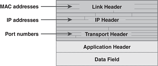
FIGURE 11.6 Address locations in packet headers.
In practice, however, our application programs rarely use the MAC addresses. Most applications use some type of socket interface, which uses IP addresses. Although MAC addresses may be sufficient in some cases, the IP address will work as long as there are routers in place and internet protocol software is present. If the hosts are on the same LAN, the internet protocols use an additional protocol to convert the IP address to the MAC address (see Section 11.3.3).
Today, the most common IP addresses are called IP Version 4 (IPv4) addresses. These addresses are 32 bits long. We represent them with a dotted decimal notation. This displays the address as a series of four decimal integers, separated by dots. Each integer represents an 8-bit portion of the IP address. FIGURE 11.7 illustrates the notation.

FIGURE 11.7 Dotted decimal notation for internet addresses.
Here are examples of addresses in dotted decimal notation:
■ 74.125.95.99—an address used by Google
■ 96.16.114.135—an address used by the White House
■ 192.168.1.12—an address used by a home router
IP Version 6
Modern network software actually provides two different IP addresses. Although most of today’s internet traffic uses IPv4 addresses, modern protocol stacks support newer, and longer, addresses in IP Version 6 (IPv6) format. Although the latest computers and network devices may support Version 6, many hosts and devices only work with IPv4. There are a few institutional and international networks that use Version 6, but the vast majority of internet services still use IPv4. Thus, when we refer to an “IP address,” we mean IPv4.
Version 6 addresses are 128 bits long, four times the size of an IPv4 address. The IPv4 address format was designed in the early 1980s, when the internet was a relatively small research network. The format started running out of addresses after the internet “went public” in the mid-1990s. The internet team that designed Version 6 hopes the new address space will last significantly longer.
Version 6 addresses are printed as a group of eight hexadecimal numbers. The hex numbers are separated by a colon with leading zeros suppressed.
11.3.2 IP Packet Format
FIGURE 11.8 shows major fields in an IP packet. The link header appears before the IP header. The link header’s “Packet type” field (see Figure 10.13) indicates that an IP header follows the link header. The IP packet’s first field indicates the IP version. In most cases, the packet is for IPv4.

FIGURE 11.8 Major IP packet fields (IPv4).
Here is a summary of the major field contents:
■ Length—the packet’s length. The IP header also contains a field that indicates the length of the header by itself.
■ Fragment—a set of fields to manage the fragmentation and reassembly of IP packets.
■ TTL—the time-to-live field described earlier.
■ Type—the type of TCP/IP transport protocol carried by this IP packet.
■ IP checksum—the checksum of the IP header fields.
■ Source IP address—the IP address of the sending host.
■ Destination IP address—the IP address of the recipient host.
■ Data field—contains the header indicated by the Type field above, and the data contents.
The IP packet may contain an optional set of additional fields called “options” that follow the destination IP address. These rarely appear in packets. If options appear, then the options will be padded with 0 bits to ensure that the header ends on a 32-bit boundary.
Packet Fragmentation
In a perfect world, all networks would carry the entire IP packet. Occasionally, however, packets must traverse a network with a smaller maximum packet size. If a packet is larger than the network’s maximum size, the packet must be broken into smaller packets. The router reformats the packet into fragments small enough to traverse the network. The router puts a copy of the IP header on each fragment. It also fills in details to describe each fragment so that the destination host can reassemble the fragments upon receipt.
11.3.3 Address Resolution Protocol
When a host needs to send a packet to another host on the same LAN, its protocol stack must convert the destination’s IP address into the correct MAC address. This is the role of the Address Resolution Protocol (ARP).
The host uses ARP to construct a table of host MAC addresses on the LAN and their corresponding IP addresses. This table, called the ARP cache, allows the network software to insert the correct MAC address when needed.
There are two ARP messages: a request and a response. The ARP request asks for the MAC address that corresponds with a particular IP address. Both use the format shown in FIGURE 11.9. The “source” in an ARP packet is always the host that sends the packet, and the “target” is always the recipient. Thus, the actual, numeric addresses in an ARP request packet appear in reverse order in the ARP response packet.
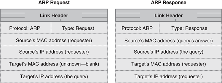
FIGURE 11.9 ARP packet contents.
The requesting host sends the ARP request as a broadcast packet. This ensures that every host on the LAN will see it. When a host receives the packet, it looks at the queried IP address to see if it matches its own address. If not, the host discards the packet. If the host’s own IP address matches the queried address, the host constructs an ARP response packet. The host sends the ARP response packet directly to the requesting host, because it knows the destination MAC address.
The ARP Cache
Every computer using internet protocols contains an ARP cache. This cache lists all of the MAC addresses and corresponding IP addresses collected and used on network traffic by that host. The ARP cache essentially keeps track of every host visited on the LAN. We can examine the ARP cache with the “arp” keyboard command, as shown underlined in FIGURE 11.10.

FIGURE 11.10 Command to display the ARP cache.
If the host’s ARP cache has few entries, it is easy to add more. We simply find the IP addresses of other LAN hosts and ping them using the “ping” keyboard command. When we ping a host, we send a simple network message that requests a brief response. The ping command requires an IP address. To actually perform the ping, the protocol stack must send an ARP request to resolve the IP request.
Some hosts are configured to ignore ping requests. This is considered a security feature because it makes the host harder to find through simple searching. However, the host will respond to the ARP request even if it ignores the ping.