


Scalability
This chapter offers guidance for designing and maintaining a highly scalable IBM API Management solution, using both qualitative and quantitative techniques. The chapter also introduces popular best practices to gather relevant key performance indicators (KPIs) and translate them for capacity planning individual nodes in the product.
Several sections explore implementing caching and service level management to design a highly scalable IBM API Management solution.
The last section highlights IBM products that can be used to transform the IBM API Management into an enterprise class software as a service (SaaS) for cloud deployments.
This chapter contains the following topics:
6.1 Introduction
In the information age, people have limited tolerance and attention spans for application unavailability, or slow responses. The impact of such failure can result in devastating consequences for an enterprises servicing these consumers. With low switching costs, consumers are readily willing to move to a competitor, resulting in lost revenue and market share; to some degree even tarnishing the brand. This phenomenon is particularly heightened in the mobile and API era. As a result, addressing scalability becomes an imperative for any enterprise hosting or supporting applications that are mobile and API centric.
The topic of scalability encompasses a wide body of knowledge and best practices (from an end-to-end perspective) that we do not attempt to address. The discussion goes beyond the scope of this chapter. This chapter primarily focuses on capacity planning and scaling the API Management solution to address predicted and ongoing demands of API usage and platform resources.
Before describing the technical product aspects of scalability, we outline several best practices in designing a highly scalable API Management platform. We acknowledge that scaling an API Management solution (or any solution) is predominantly an art form, combining market, industry and technical domain expertise at various levels. As a result, a “one size fits all” approach is not advocated here. We attempt to merge best practices accepted in the industry with the product capabilities to get closer to designing a solution that can efficiently withstand your predicted or ongoing capacity.
Also, a common misconception exists and is worth addressing because our guidance on the subject entails understanding various facets of scalability. The misconception is that scalability is concerned with primarily adding more capacity to support business needs. Although this is true in many cases, equally strong reasons exist for reducing capacity, also. As IT budgets and resources are limited, careful consideration should always be given to utilizing resources in the most efficient manner, to reduce cost and waste.
6.2 Best practices
Before undertaking the effort to size an API Management solution, several aspects should be considered to serve as input to sizing decisions. An understanding of the customer and the target market can help reduce some of these seemingly open-ended questions:
•How many external developers will be targeted? Is the number in the hundreds, thousands, or millions of subscribers?
•How many applications will be supported per API? If the APIs are being exposed to closed group then that number can be easily predicted. If it is open to all, a good starting measure could be in the hundreds of subscribers.
•How many intended end users will use these APIs? Is it in the thousands, or millions of subscribers?
•How many versions of each API will be hosted?
Answering these kinds of questions might lead you to an aggregate approximate figure for how many API calls and portal invocations will need to be supported. With this information, further clarity can be achieved by answering some questions at a more technical level:
•What throughput should the solution support?
|
Throughput: Several definitions exist for measuring throughput. Within the context of API Management, throughput typically refers to the number of API calls (transactions) per second.
|
•What is the acceptable latency threshold for API calls?
•How many concurrent API calls can be supported?
•What is the acceptable size of payload that should be allowed?
•Should the payload be persisted for reporting, replaying, or troubleshooting?
•Is every API response content unique?
Responses to these questions should further lead to defining end-to-end requirements for an API Management solution. End-to-end requirements might involve building sufficient capacity, geographical affinity, and high-availability on your networks, back-end applications, and databases. A Content Delivery Network (CDN) might also be used to reduce latency on the public network.
6.3 Capacity planning
After capturing the general KPIs and relevant metrics for predicted capacity, additional questions should be considered that are unique to the IBM API Management solution:
•In a multitenant environment, how many tenants will be serviced in this environment?
|
Multitenants: Multitenancy is a cloud computing concept that refers to slicing all tiers of an IT architecture to allow multiple customers (tenants) share applications, computing resources, or both, in a self-contained manner, without compromising security, reliability, and consistent performance.
|
•Will API payload details be recorded?
•What is the accepted retention period for API payload details?
•What is the API call percentage split between leveraging Proxy and Assembly capabilities?
High-availability also plays a critical role in designing for enterprise scale. In a production and sandbox environment, each node of the IBM API Management solution should at a minimum be deployed in pairs, as shown in Figure 6-1 on page 109. In a non-production environment, a single node for each component should suffice.

Figure 6-1 Nodes in pairs for high availability
All of the information collected so far might apply differently to each node, because each node is responsible for different capabilities that are not used equally across the product.
6.3.1 Sizing the Management node
The Management node is responsible for monitoring and managing the API Management environment. This node also hosts the Administrator Console, API Manager Portal and the Developer Portal.
To provide high availability in a production and sandbox environment, at least two nodes will be required per environment, unless they are separate tenants on the same installation.
In non-production environments, a single node might suffice, although two nodes are recommended for production environment.
|
Notes:
•One node can support up to 25 tenants. If more tenants are required, then an additional nodes might need to be deployed.
•The latest available IBM API Management product version 2.0 (Fixpack 1) at the time of this publication supports a maximum of two management nodes per cluster.
|
6.3.2 Sizing the Analytics node
The Analytics node is responsible for capturing and retaining transactional metadata and payload details (if enabled) from incoming API calls. The data is held in an internal persistent store until the retention period, defined by the administrative policy.
|
Note: Metadata accounts for 1 Kb per call, even when payload details are not captured.
|
The following primary factors are for sizing the Analytics node:
•Number of API calls (throughput)
•Size of API payload content, for request and response (in kilobytes)
•Duration of data retained (in months)
After these numbers are captured, follow the guidance suggested in Table 6-1.
Table 6-1 Template for sizing Analytics node
|
Metric
|
TPS1
|
Search data requirement
|
Number of shards2
|
Number of nodes
|
|
Small
|
10
|
300
|
15
|
2
|
|
Medium
|
50
|
1500
|
75
|
10
|
|
Large
|
100
|
3000
|
150
|
20
|
|
Average message size (KB)
|
10
|
GB/Shard
|
20
|
|
|
Data retention (months)
|
3
|
Shard/Node
|
|
|
1 TPS is transactions per second.
2 Shard is a horizontal partition of a database.
For high availability in the production and sandbox environment, the recommendation is that two nodes be deployed at a minimum, even if capacity can be handled by a single node.
6.3.3 Sizing the Gateway node
The Gateway node is responsible for all API calls flowing through the solution. It also participates in intra-communication with the Management and Analytics node that you might want to consider for capacity planning.
A single Gateway node (virtual, or hardware appliance) can support thousands of transactions in a stand-alone configuration; however, network conditions, available bandwidth (1 GB or 10 GB), size of payloads, CPU clock speed (in virtual), allocated number of CPUs (in virtual), and allocated memory (in virtual) might be critical factors to consider when you design a capacity plan.
Latency and availability to back-end application servers, databases, or network systems (for example, DNS) might affect the level of resource consumption and processing latency on the node. These factors might have measurable impact on available peak throughput. Performance benchmark testing in a pre-production tier can reveal the impact of these factors on throughput within the environment.
We suggest several best practices for benchmark-testing the Gateway node that can be conducted in three phases, with increasing levels of complexity.
1. In phase one, focus on benchmarking a single node where round trip latency is minimized using load generation tools and loopback providers.
2. During phase two, preproduction back-end and supporting servers (for side-calls) should be introduced by replacing the loopback providers.
3. Finally, in phase three, the environment should represent a production environment before conducting a benchmark test.
At the end of each phase, capture performance reports and logs so that they can be analyzed and compared. The results can reveal where the bottlenecks potentially reside, or confirm sufficient capacity. When tuned satisfactorily, load should be increased until resource exhaustion. This exercise reveals the high watermark throughput that a single Gateway node can support.
|
Note: Additional considerations should be taken into account if the Gateway node is customized, through the DataPower extensions feature. These extensions might include, for example, JSON schema validation, or external calls to an antivirus server over Internet Content Adaptation Protocol (ICAP).
Extensions can introduce measurable latency and consume resources leading to reduced throughput on the Gateway node. Therefore, conduct performance testing to understand the maximum throughput and concurrent connections the device can handle under these conditions.
|
One of the great attributes of the Gateway node is that it offers predictable scalability using a horizontal scaling strategy. This assures that scalability of the Gateway node can be predicted on a linear scale. For example, if a single Gateway node supports a thousand transactions per second, a second node should double the capacity to processing two thousand transactions per second.
High availability (HA) is also closely tied to scaling a Gateway node. Typically a highly available solution should constitute a pair of Gateway nodes, at a minimum. Although your throughput requirements may dictate adding additional nodes to meet your expected goals.
Another good rule to consider is that the Gateway node cluster should be able to support N+1, or N+M configuration. That means if one node crashes, or must be serviced, the remaining nodes can handle peak traffic rates reliably. For example, if you have a pair of Gateway nodes deployed in active-active mode, each should be allocated to handle 50% of peak traffic throughput; although, if the choice is to maximize resources by using full capacity on each node then consider adding a third node in passive mode. The passive node instance will take over, when any one of the active nodes become unavailable. Instructions to configure standby-control groups (a network mechanism to enable active-active or active-passive modes) are available in the DataPower information center, under the “Standby configurations” topic.
The choice to start with two nodes might likely become a moot point; as in many cases, a pair of nodes are likely a starting point to address HA. However, enterprises that are extremely sensitive to SLAs are planning to target a large audience at the outset, or have sufficient IT resources at their disposal, should consider the best approach described previously. The advocated quantified approach offers greater precision and control over your capacity planning goals.
|
Note: A safe assumption, based on lab trials and customer deployments, is that two Gateway hardware appliances are more than sufficient for enterprises that are considering small to medium sized entry level deployments: constituting lower throughput (tens of TPS, concurrent connections, or both), small payloads, and no Gateway extensions.
|
6.3.4 Sizing the Assembly node
The Assembly node is an optional component of the IBM API Management solution. It provides the capability to assemble your APIs.
The Assembly node is primarily influenced by the following factors:
•Cacheability of requests
•Volume of assembly resources
•Number of concurrent requests
The ability to cache requests in the Assembly node reduces the number of jobs the Assembly node requires to execute.
The volume of assembly resources can be calculated using the following formula:
TPS * %-assembly * (1-cache %)
The number of concurrent requests supported is currently limited to 100 threads per node.
After quantifying this data, the guidance in Table 6-2 can help size this node.
Table 6-2 Template for sizing Assembly node
|
Metric
|
TPS1
|
CPU (Cores)
|
Memory
|
Hard Disk
|
|
Small (TPS/month)
|
10
|
1 (2)
|
4 GB
|
500 MB
|
|
Medium (TPS/month)
|
50
|
2 (4)
|
8 GB
|
1 GB
|
|
Large (TPS/month)
|
110
|
4 (8)
|
16 GB
|
2 GB
|
1 TPS is transactions per second
Each resource or assembly is a separate project, or orchestration in the Assembly node. Because this node is based on the IBM WebSphere Cast Iron Appliance that is noted to have a practical limit of supporting 200 - 300 projects, you can assume the same limit will apply to a single Assembly node. If you predict, or discover over time, that more assembly resources are required across all APIs and tenants, then you must add more Assembly nodes to your environment.
For production and sandbox, strongly consider deploying, at a minimum, a pair of Assembly nodes to provide high availability. A single node should ideally be able to support 100% traffic in the advent one of the appliances becomes unavailable.
6.4 API caching
Caching is a popular technique used to improve overall system performance and reduce application wait times. It allows a system to hold the data in memory for a defined period of time, or use a queuing algorithm to add and remove cache entries.
The primary purpose for caching is to remove the dependency to engage with the system of record origin. Rather than conducting expensive processing to retrieve data from the original system of record, the data can be retrieved fast and efficiently from memory.
A highly scalable enterprise solution will likely entail enabling caching on most systems from the point of origin to the destination. This could entail the network, software, operating system, or even the hardware. The IBM API Management solution is no exception and includes configuration driven policies for caching API responses, as highlighted in Figure 6-2 on page 115.
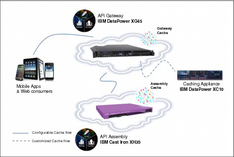
Figure 6-2 Caching in IBM API Management
Caching in IBM API Management follows the HTTP 1.1 specification for enabling caching through the injection of cache-control headers. These cache-control headers are configured during design-time of the API. Figure 6-3 on page 116, displays the section for adding comma-separated HTTP 1.1 cache-control headers. Below the section, it also includes documentation of commonly used cache-control headers, as a reference for anyone who is not familiar with HTTP 1.1 caching directives.
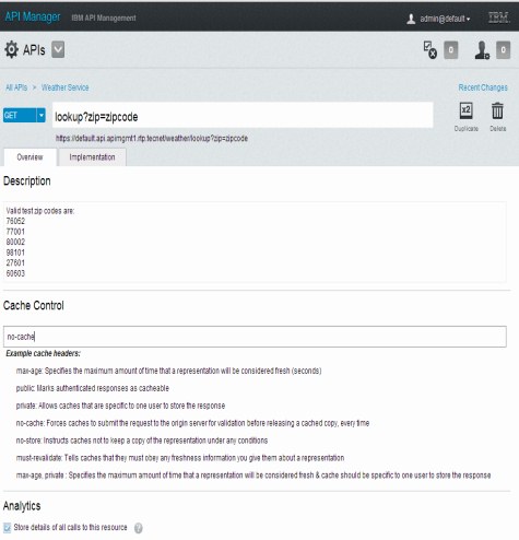
Figure 6-3 Configure caching for assembly
|
Note: Cache-control headers assigned in this pane only pertain to API transactions that are configured for assembly (requiring the Assembly node). Although these header directives can be defined when the API is configured as a Proxy, they will take affect only on the Assembly node and not the Gateway node.
|
The IBM API Management solution does support caching in the Proxy mode; however, those configurations are defined outside of the API Manager portal through the DataPower gateway’s native user interface. Details for configuring on-board caching on DataPower gateways are in the WebSphere DataPower Information Center, under Document Cache Policies. The Gateway node may also be configured to connect externally to a WebSphere XC10 caching grid. For details, see the WebSphere DataPower Information Center, under XC10 Integration.
6.5 Service level management
Sustaining a solution that can be resilient to peak demands and scale accordingly, makes service level management a critical part of an enterprise scalability strategy.
Service level management, illustrated in Figure 6-4, is an important discipline to ensure a service is provided in meeting expected or predefined quality of services (QoS) both from a consumer and provider perspective. In a business-to-business (B2B) setting, this is traditionally enforced through service level agreements (SLAs), that manifest in an implicit, or explicit contract to deliver previously agreed upon levels of service.
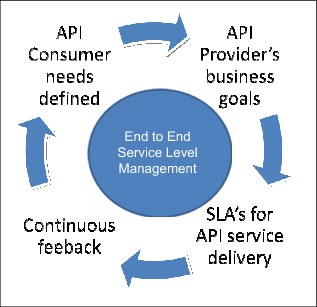
Figure 6-4 Service level management
The IBM API Management solution, provides two key features that implement the service level management feature.
•Predefined SLAs enforced through Entitlements; deals with managing the environment through SLA enforcement
•Capacity adjustment based on trend analysis through Analytics; provides the monitoring capability to adjust capacity in response to on-going processing demands
Although both features can be used to adjust and enforce available capacity, they can also serve as vital input into determining your Entitlements goals, which might have been primarily influenced by the chosen pricing model.
|
Quality of service (QoS): The term QoS covers a whole range of techniques that match the needs of service requestors with those of the service provider's based on the resources available. This can refer to non-functional properties of APIs such as performance, reliability, availability, and security.
Service level management (SLM): The term SLM applies to monitoring and management of QoS’s. SLM provides a mechanism to compare realized QoS (example, latency, or number of calls) with agreed upon expectations. Based on this information, appropriate actions can be taken and relevant reports can be generated for further analysis and tuning.
Service level agreement (SLA): SLA is a contract between the service provider and consumer that outlines, usually in quantifiable terms, which QoSs will the provider adhere to.
|
6.5.1 Enforcing SLAs through Entitlements
Enforcing SLAs through Entitlements serves multiple but different purposes from the perspective of a consumer, or a provider role.
•For a consumer:
– Sets an expectation for how many API calls a developer or Application can invoke for the assigned Entitlement level.
– Enables selection of Entitlement level based on grouping.
•For a provider:
– Enforces the maximum number of API calls allowed within the given time period (for example, minute, hour, week or month).
– Ensures the aggregate number of API calls can be serviced without overwhelming the API Management platform, including dependent back-end systems and underlying network.
Defining Entitlements in the IBM API Management is described in more detail in Chapter 4, “Entitlements” on page 71.
6.5.2 Capacity planning using Analytics
The Analytics capability in IBM API Management provides detailed real-time reporting of API usage patterns, loads, and time frame of activity. Analytics reporting provides vital information such as trends that can be gleaned upon to plan for addition, or reduction in capacity.
A more comprehensive overview of the Analytics function is covered in Chapter 10, “Analytics” on page 217. In this section, we primarily focus on using Analytics to address capacity needs based on measurable metrics.
Multiple Analytics views provide various levels of perspectives. These can be combined to produce rich and granular insight into adjusting capacity to maximize usage while maintaining predefined SLAs, or to add more nodes because of expected surge, based on a trend analysis.
Environment Console monitoring view
The Environment Console monitoring view presents real-time graphs of compute resources for each node. The graphs also highlight when an individual resource is nearing its maximum threshold.
To access the monitoring view through a browser, log in to the Environment Console and select the Monitoring Environment view, shown in Figure 6-5 on page 120. This view provides a listing of all the nodes configured in your environment. When you click on a particular node, resource graphs will be displayed on the right side.

Figure 6-5 Monitoring node resources
Resource usage based on reported statistics can be assessed to determine whether the nodes are being efficiently utilized and not over-burdened. Based on this information, consider adding or reducing the number of nodes.
See Chapter 10, “Analytics” on page 217 for more details of how to interpret the resource metrics.
API Manager analytics view
The API Manager portal includes several Analytics views revealing details of API consumption patterns. The Dashboard view provides a high-level snapshot of the highest number of calls being processed per API, developer, or application.
To access the API Management view through your browser, log in to the API Manager portal, and click Dashboard (Figure 6-6).
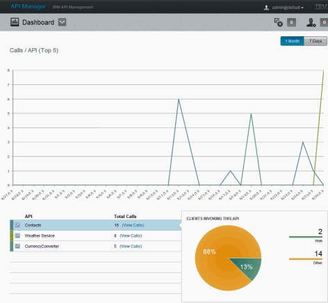
Figure 6-6 Analytics Dashboard
The API Manager Dashboard illustrates key metrics that can be used to predict capacity, based on ongoing demand. Not all APIs are created equal. Some APIs are more resource-intensive than others because they might include complex processing, or callouts to other systems. This can place higher demand on the platform, especially with response time SLAs as a binding factor.
By correlating sources of callers to APIs, it is possible to predict whether current capacity will uphold for the APIs in question. The data generated can also help identify whether the highlighted APIs are not disproportionately consuming resources. Perhaps sufficient capacity might need to be reserved for low usage but high value APIs. Insights such as these can help you take appropriate action to maintain (or reduce) capacity to maximize resource allocation at optimal levels.
Aside from the analytics Dashboard, a capacity planner can use other features to drill down at a detailed level of each API for further analysis. These features are labeled API Statistics, and Search & Analyze, in the API Manager portal drop-down view. We cover them in greater depth in 10.2, “API product manager” on page 219.
6.6 Cloud deployments for enterprise scale
The IBM API Management solution currently offers two forms of deployment choices, allowing complete flexibility in using new, or existing virtualized assets:
•A fully virtualized environment that is cloud-ready
•A mixed environment that combines virtualized images and hardware appliances
Enterprises that are considering large scale cloud deployments of the IBM API Management solution have the option to use two IBM products, designed to manage these kind of deployments through automated management and provisioning:
•IBM PureApplication™ system
•IBM Workload Deployer
Either product can significantly reduce the cost and operational overhead of maintaining and maximizing people and IT resources for hosting cloud computing environments.
6.6.1 IBM PureApplication system
IBM API Management supports cloud deployments with IBM PureApplication System W1500.
IBM PureApplication System is an integrated, highly-scalable system that is based on IBM X-Architecture®, providing an application-centric computing model in a cloud environment.
An application-centric system is an efficient way to manage complex applications and the tasks and processes that are invoked by the application. The entire system implements a diverse virtual computing environment, in which different resource configurations are automatically tailored to different application workloads. The application management capabilities of the PureApplication System platform make deployment of middleware and other application components quick, easy, and repeatable.
PureApplication System provides virtualized workloads and scalable infrastructure that is delivered in one integrated system:
•Virtualized system and application workloads, including these features:
– Integrated middleware like IBM WebSphere Application Server, web server, DB2®, and hypervisor images
– Elastic data
– Application-centric workloads created using pattern types such as web application patterns, database application patterns, and topology patterns
•Scalable infrastructure, including these features:
– Optimized hardware tuned for running workloads.
– Isolated networking for secure communications.
– Server resiliency to prevent overload or failures.
– Dynamic storage.
•Integrated delivery, including these features:
– Factory assembled and wired system.
– Tuned for maximum efficiency of data, storage, workload execution, and retrievability.
– Simple approach to managing all integrated components and monitoring health of the system.
– Single pane of glass management for administrator and application deployment.
The procedure to deploy IBM API Management virtual (OVA1) files with PureApplication is documented in the IBM API Management Information Center; search for the “Installing virtual appliances on IBM PureApplication System” topic.
6.6.2 IBM Workload Deployer
IBM API Management supports cloud provisioning with IBM Workload Deployer v3.1.0.7. IBM Workload Deployer is an appliance that is packaged with software to manage resources in a cloud computing environment.
IBM Workload Deployer uses workload patterns to create consistent, validated, and repeatable virtual applications within the cloud environment. Workload patterns are solutions that enable the deployment of complex business applications in a cloud environment. When you use a workload pattern, you can focus on an application as opposed to the middleware infrastructure in which the application runs. For example, if an application consists of a WebSphere Application Server application, a database schema, and an LDAP program to manage users, you deploy these applications and IBM Workload Deployer installs and configures the required middleware, and manages the application run time using policies that you define.
The IBM Workload Deployer appliance is a 2U rack-mountable appliance that can be placed in a data center. The appliance can dispense applications and topologies into a pool, or cloud of virtualized hardware, and manage resources. The resources are running on IBM PowerVM®, IBM z/VM®, or VMware hypervisors.
IBM Workload Deployer manages the people, places, and things in your cloud-computing environment. Cloud computing is a computing paradigm in which data and services are located in data centers. The data and services can then be accessed from any connected devices over the Internet. Applications can use the cloud for added value, such as storage, queuing, and hosted applications. The applications themselves can also be hosted on the cloud.
IBM Workload Deployer manages the following resources:
•People, which are the users of the system.
•Places, which are the servers, network, and storage to run applications.
•Things, which are virtual images, virtual system patterns, virtual system instances, and virtual application instances.
The procedure to deploy IBM API Management virtual (OVA) files with IBM Workload Deployer is documented in the IBM API Management Information Center; search for the “Installing virtual appliances on IBM Workload Deployer” topic.
1 Open Virtualization Format Archive (OVA)
..................Content has been hidden....................
You can't read the all page of ebook, please click here login for view all page.