
CHAPTER 7
Covalent Binding of Polycyclic Aromatic Hydrocarbon Systems
7.1 INTRODUCTION
Polycyclic aromatic hydrocarbons (PAHs) are a class of compounds that are made up of fused aromatic rings and comprise of only carbon and hydrogen. Some examples of PAHs are shown in Fig. 7.1, which consist of the acene members, perylene, coronene, dibenzo[a, j]coronene, and acenaphthylene. The acenes are made up of linearly fused benzene rings, of which naphthalene, anthracene, tetracene, and pentacene are the most commonly studied molecules. Due to the sharing of π-orbitals between adjacent rings in PAHs, each ring segment possesses a different degree of aromaticity, according to Clar's sextet concept [1]. For instance, only one ring within naphthalene and anthracene can be assigned three double bonds without duplication and be considered as an aromatic sextet. The sextets are represented by the circles in Fig. 7.2, which are mobile within the molecules via the movements of two π-electrons as symbolized by the arrows. The highly conjugated π-electron system within the PAHs also makes them highly sought after as the active semiconducting materials in organic electronics [2]. Specifically, pentacene has aroused great attention due to its remarkable field-effect mobility that is comparable to that of amorphous silicon. Examples of organic electronic devices that incorporate pentacene are field-effect transistors [3,4] and solar cells [5]. Besides pentacene, tetracene is another PAH that has been successfully employed for fabrication of light-emitting devices [6], photodetectors [7], and solar cells [8].
Numerous studies have been done on the adsorption of PAHs on the silicon surfaces. This is due to the interest of coupling organic functionalities with the silicon surfaces to create new technological opportunities for fabrication of silicon-based organic-inorganic hybrid devices [9]. Such devices exploit the functional flexibility of organic molecules and the well-established silicon process technology to offer new and enhanced properties integrated with the silicon substrate. Since PAHs exhibit potentials for applications in organic electronic devices, achieving an atomistic understanding of their binding configurations on the silicon surfaces is of industrial as well as scientific interest. Specifically, it is well known that the charge transport and optical properties of a film are influenced by the interactions between its constituent molecules and hence its morphology [10]. Hence, in order to design the optimum conditions for growing PAH films on silicon, a thorough knowledge of the interfacial chemistry between the PAHs and the silicon surface is critical because the first molecular layer on the substrate is going to affect the growth of subsequent PAH molecules.
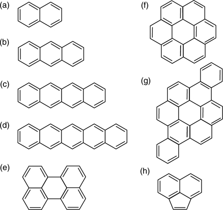
FIGURE 7.1 Some examples of polycyclic aromatic hydrocarbons: (a) naphthalene, (b) anthracene, (c) tetracene, (d) pentacene, (e) perylene, (f) coronene, (g) dibenzo[a, j]coronene, and (h) acenaphthylene.
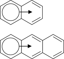
FIGURE 7.2 Clar's sextet concept illustrated for naphthalene and anthracene. The aromatic sextets of six π-electrons, represented by the circles, are mobile within the molecules via movements of two π-electrons as symbolized by the arrows.
The results obtained from the studies of various PAHs on the silicon substrates provide insight to the reaction mechanisms and binding configurations of these molecules on the Si(100)-(2×1) and Si(111)-(7×7) surfaces, which will be reviewed in this chapter. For practically all cases, the adsorbates form strong C–Si covalent bonds with the substrates that involve the transformations of the reacted carbon atoms from sp2 to sp3 hybridization. Due to the rupture of the π-conjugation in the reacted ring, the overall aromaticity of the adsorbate differs from that of the free molecule. Various binding configurations are possible in many of the systems studied and their relative binding energies are influenced by the resultant aromaticity of the molecules. Generally, adsorbates with structures that are able to sustain π-conjugation or an aromatic sextet of six π-electrons, as governed by Clar's concept, are more stable than those with bent or twisted structures with perturbed π-conjugation. Furthermore, the possible binding configurations are greatly influenced by the dimensions of the adsorbates relative to the positions of the silicon dangling bonds. For the Si(100)-(2×1) surface with rows and columns of Si dimer rows, the molecules mostly adopt orientations that are parallel or perpendicular to the dimer rows. As for the Si(111)-(7×7) surface, the adatom–rest atom pair plays an important role in the di-σ reaction with two opposite carbon atoms from the same benzene ring within the molecule. Due to the strong interactions between PAHs and the silicon surfaces, the adsorbates typically adopt an almost flat-lying orientation on the substrates. Section 7.2 focuses on the adsorption of various PAHs on Si(100)-(2×1) while the interactions of the acenes on Si(111)-(7×7) will be reviewed in Section 7.3. For easy reference, PAHs with labeled carbon atoms and rings will be shown in some of the sections and descriptions of numbered carbon atoms in the text will be made with reference to the diagrams.
7.2 PAHs ON Si(100)-(2×1)
7.2.1 Naphthalene and Anthracene on Si(100)-(2×1)
Naphthalene and anthracene are made up of, respectively, two and three linearly fused benzene rings and hence constitute the basic structures of the larger acene members. The adsorptions of naphthalene and anthracene on Si(100)-(2×1) were investigated by Okamura et al. based on infrared reflection-absorption spectroscopy (IRAS) and density functional theory (DFT) calculations [11,12]. Similar to benzene, the adsorption of naphthalene on the surface exhibits strong coverage dependence. At low exposure, naphthalene binds to two adjacent Si dimers through four C–Si σ-bonds involving C1, C2, C5, and C6 of the adsorbate (Fig. 7.3a). This configuration, referred to as “symmetric bridge” (SB), is energetically more favorable as compared to other configurations such as “rotated symmetric bridge” (RSB) and “tight bridge” (TiB), though the aromaticity within naphthalene is completely lost in the SB binding mode (Fig. 7.3b). However, both IRAS and DFT calculations indicate the presence of multiple configurations of naphthalene, comprising of SB, RSB, and TiB, on Si(100)-(2×1) at high coverages. DFT calculations performed for two adsorbateson silicon models (Fig. 7.3c) show that combination of [SB,SB] is energetically less stable than [SB,RSB] and [SB,TiB]. This is attributed to the larger steric repulsion between the hydrogen atoms of the two adjacent adsorbates along a dimer row for the [SB,SB] model.
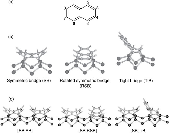
FIGURE 7.3 (a) Structure of naphthalene. Configurations of (b) one and (c) two naphthalene molecules chemisorbed on Si(100)-(2×1) (from Ref. 11).
On the other hand, the adsorption of anthracene (Fig. 7.4a) on Si(100)-(2×1) exhibits less coverage dependence. This is suggested by the similar IRAS spectra peaks at different coverages of anthracene on Si(100)-(2×1), as shown in Fig. 7.4b [12]. Furthermore, the presence of peaks within the 2800–3000 cm−1 range of the spectra indicates the conversion of some of the anthracene carbon atoms from sp2 to sp3 hybridization due to their reactions with the substrate. Comparisons of these spectra with those obtained from frequency calculations (presented in the lower half of Fig. 7.4b) suggest that anthracene exists in two configurations along the dimer row, referred to as structures 1 and 2. In structure 1, anthracene forms C–Si bonds with three adjacent pairs of Si dimers via C2, C4, C5, C7, C9, and C10. In structure 2, two adjacent pairs of Si dimers interact with C1, C3, C6, and C8 of anthracene.
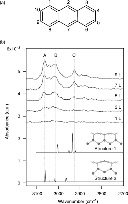
FIGURE 7.4 (a) Structure of anthracene. (b) IRAS spectra for anthracene adsorbed on Si (100)-(2×1) as a function of exposure expressed in units of langmuir. The calculated spectra for two possible adsorption configurations (structures 1 and 2) are shown in lower half of the figure (from Ref. 12).
7.2.2 Tetracene on Si(100)-(2×1)
The adsorption of tetracene (Fig. 7.5a) on Si(100)-(2×1) had been studied using scanning tunneling microscopy (STM) [13,14], angle-resolved ultraviolet photoelectron spectroscopy (ARUPS) [15], and DFT calculations [15]. Similar to the cases for naphthalene and anthracene, the ARUPS results suggest that the tetracene adsorbates lie parallel to the substrate surface. Indeed, the filled state STM image of tetracene on Si(100)-(2×1), as shown in Fig. 7.5b, exhibits feature sizes that are consistent with the long axis of a tetracene molecule. Furthermore, surface features that correspond to two types of chemisorbed tetracene (referred to as configurations A and B) are apparent. Configuration A lies perpendicular to the Si dimer rows and comprises of three bright spots with the middle dimmer spot centered over a dimer row. On the other hand, configuration B appears as two bright spots that are aligned parallel to the dimer rows. Based on these STM images, Rada et al. proposed that tetracene in configuration A forms four C–Si bonds with two adjacent Si dimer pairs via the meso carbon atoms of rings II and III (C2, C3, C8, and C9), as shown in Fig. 7.5c. In configuration B, the tetracene adsorbate adopts a symmetrical structure along the dimer row as the central two carbon atoms (C2a and C8a) bind to a pair of Si dimer (Fig. 7.5c). However, it is noted that such a binding configuration involving the central fused carbon atoms has been shown to be thermodynamically unfavorable on Si(111)-(7×7) through theoretical calculation (see Section 7.3.2).
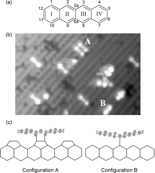
FIGURE 7.5 (a) Structure of tetracene. (b) Filled state STM image of Si(100)-(2×1) with adsorbed tetracene. Observed features are labeled “A” and “B” that corresponds to two types of binding modes. (c) Structures of binding configurations A and B of tetracene on Si(100)-(2×1) as proposed by Rada et al. (from Refs. 13 and 14).
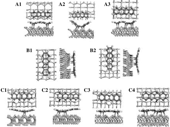
FIGURE 7.6 Different binding configurations of tetracene on Si(100)-(2×1) as calculated by DFT techniques (from Ref. 15).
The binding energies of various configurations of tetracene on Si(100)-(2×1), based on DFT calculations, have been compared by Mao et al. [15]. As shown in Fig. 7.6, configurations A1–A3 represent tetracene adsorbates on the dimer row, B1 and B2 denote configurations with the long axes of tetracene aligned perpendicular to the dimer rows, and C1–C4 represent configurations for tetracene adsorbed between two dimer rows. Configuration B1, with C1, C2, C4, C7, C9, and C10 of tetracene forming six C–Si bonds to the Si dimers, was found to be the most stable structure. Configuration B2, which corresponds to configuration A as proposed by Rada et al. and possesses only four C–Si bonds, is 22.4kcal/mol less stable than B1. However, the adsorbate in configuration B2 has two aromatic sextets at the outer rings I and IV, whereas tetracene in configuration B1 has only one such sextet in the inner ring II (or ring III). On the other hand, configuration B from Rada et al. was not calculated by Mao and possible assignments of calculated configurations A1–A3 and C1–C4 to STM features observed by Rada et al. require further studies such as STM image simulation.
7.2.3 Pentacene on Si(100)-(2×1)
Due to the technological importance of the Si(100) surface as well as the potential pentacene exhibits as a material with relatively high field-effect mobility, the adsorption of pentacene on Si(100)-(2×1) has been intensively studied using both experimental [16–21] and theoretical techniques [19,22–24]. Based on STM results, Kasaya et al. identified three types of orientations for the chemisorbed pentacene on the substrate, which comprise of configurations with the adsorbate lying parallel to the Si dimer rows (type A), perpendicular to the dimer rows (type B), and diagonal to the dimer rows (type C) [16]. Type A and B configurations can be further divided into subtypes based on their appearances or number of bright sections in the STM images. They comprise of A1 (two sections), A2 (three sections), B1 (two sections), and B2 (three sections). Hughes et al., on the other hand, did not observe the type C configuration from their STM data, but were able to detect another configuration with the pentacene adsorbate aligned parallel and in-between two Si dimer rows (configuration IB) [17].
Combining the results from STM and DFT calculations, Suzuki et al. proposed the binding configurations for A1, B1, B2, and IB, as shown in Fig. 7.7 [20]. The STM images of these four binding modes are shown in Fig. 7.7a–d(i), where the white markers indicate the positions of the Si dimers. A1, B1, B2, and IB were observed to be the major configurations and exist, respectively, with 20%, 15%, 45%, and 15% probability. Their simulated STM images, based on the proposed structures, agree well with the experimental images. Configuration A1, as shown in Fig. 7.7a(ii) and (iii), has eight carbon atoms from pentacene (lighter shade) bonded to the silicon atoms from the same dimer row. The nonplanar structure is symmetric with respect to the center of the adsorbate and possesses a binding energy of 104.5 kcal/mol. Configuration B1, which has pentacene oriented perpendicular to the Si dimer rows, possesses a higher binding energy of 127.8 kcal/mol and is depicted in Fig. 7.7b(ii) and (iii). This binding mode has the same number of C–Si bonds and positions of bonded pentacene carbon atoms (lighter shade) as A1 but has less degree of bending for the adsorbate. Figure 7.7c(ii) and (iii) shows the optimized structure for configuration B2, another subtype of configuration B. In contrast to B1, however, the structure of pentacene in B2 is asymmetric and possesses only six C–Si bonds. The binding energy of this configuration was calculated as 100.7 kcal/mol. The IB configuration, with the adsorbate aligned between two Si dimer rows, is shown in Fig. 7.7d(ii) and (iii). This configuration has the same structure as A1 and B1 except for the orientations with respect to the underlying dimer rows. The binding energy of configuration IB is 67.1 kcal/mol, which is less than both A1 and B1. The lower energy is attributed to the rearrangement of four pairs of buckled Si dimers from the down to the up positions due to the chemisorbed pentacene in the IB configuration. Besides the four major binding modes, Suzuki et al. also observed configurations A2, C, and a new A3, which together made up for the remaining 5% of the adsorbed pentacene.
The configurations that correspond to type A1 and B1, as proposed by Suzuki et al., have also been found to be the most stable structures for configurations A and B, respectively, via theoretical calculations performed by Choudhary et al. [23] and Nunzi et al. [24]. Both research groups, however, relate the stable tetradimer type A configuration to the A2 binding mode, due to the three bright sections for A2 in the STM images. Interestingly, the experimental STM images for A1 agree with the simulated image calculated by Suzuki et al., who further argued that the central node for the A1 STM feature originates from electronic, rather than topographic factors. As for configuration B1, Choudhary et al., Nunzi et al., and Suzuki et al. agree upon it as being the most stable configuration for the chemisorbed pentacene on Si(100)-(2×1). The high stability could be attributed to the eight C–Si bonds present as well as the snug fit of pentacene within the adsorption site that helps to minimize any bending of the molecule (Fig. 7.7b(ii) and (iii)). Furthermore, the planar and unreacted central benzene ring allows good overlapping of adjacent π-orbitals that ensures the aromaticity of the ring and hence extra stability for the whole structure.
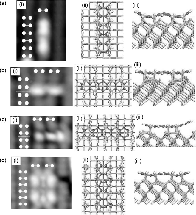
FIGURE 7.7 (i) Experimental STM images and (ii) top and (iii) side views of pentacene on Si(100)-(2×1) in binding configurations (a) A1, (b) B1, (c) B2, and (d) IB (from Ref. 20).
Overall, the various binding configurations of pentacene on Si(100)-(2×1) as observed by STM adopt a flat-lying orientation on the surface. This is in correspondence to the data obtained from other techniques, such as valence band photoemission studies [17], IRAS [19], near-edge X-ray absorption fine structure (NEXAFS) [21], and theoretical calculations [19,22–24]. Furthermore, the appearance of the Si–H vibration peak from Fourier transform infrared spectroscopy (FTIR) data suggests the occurrence of a limited amount of dissociation of the adsorbed pentacene in addition to its molecular chemisorption [18]. This is supported by theoretical work that studies the energetics and kinetics of dissociative adsorption of pentacene on Si(100)-(2×1) [24]. The results show that it is a kinetically favorable process for two hydrogen atoms from the sp3 carbon atoms of apentacene adsorbateinthe IB configuration to be abstracted by two silicon atoms of two dimers bearing unpaired electrons.
7.2.4 Perylene on Si(100)-(2×1)
Perylene constitutes the core structure of the well-known organic semiconductor, 3, 4, 9, 10-perylene-tetracarboxylic dianhydride (PTCDA), which has been studied as the active material in organic solar cells. It is interesting to note that perylene, in contrast to other studied PAHs, was found to adsorb in an upright position on Si (100)-(2×1) [14,25]. The STM image of chemisorbed perylene on Si(100)-(2×1) is shown in Fig. 7.8a [14]. Chain-like structures that are aligned perpendicular to the Si dimer rows are apparent. Furthermore, each block making up the chain is comprised of five-units of bright features, with individual features being assigned to a single perylene molecule. The length of the brightest feature is 11.35 Å, which is comparable to the longer axis of a perylene molecule of 11.25 Å. Rada et al. proposed that C8 and C11 of perylene form C–Si bonds with the substrate, via C–H bond cleavage and Si–H bond formation. With C8 and C11 remaining in the sp2 hybridization, perylene chemisorbs in an upright position and on top of two Si atoms from two pairs of adjacent Si dimers, as depicted in Fig. 7.8b.
The binding configuration of perylene on Si(100)-(2×1) as proposed by Rada et al. is consistent with the experimental and theoretical high-resolution electron energy loss spectroscopy (HREELS) data from Preuss et al. [25]. Based on DFT method, Preuss et al. simulated the HREELS spectra of various binding configurations of perylene on Si(100)-(2×1) and found that only the spectrum that was simulated based on the binding model from Rada et al. is in agreement with the experimental HREELS data.
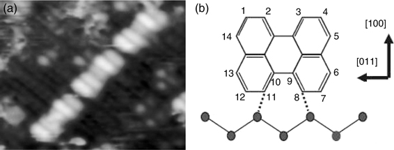
FIGURE 7.8 (a) Filled state STM image and (b) proposed binding configuration of perylene on Si(100)-(2×1) (from Ref. 14).
7.2.5 Coronene on Si(100)-(2×1)
Coronene is comprised of six peri-fused benzene rings and can be described by a set of three mobile Clar's aromatic sextets. The adsorption of this molecule on Si(100)-(2×1) has been investigated using STM combined with DFT calculations [26]. Three binding configurations have been identified, which include a major on-top binding mode (~80% of the total population) and two minor substrate defect-related binding modes.
Figure 7.9a(i) shows the filled state STM image (white markers indicate positions of the Si dimers) for the on-top binding mode, which is in good agreement with the simulated image based on the configuration as shown in Fig. 7.9a(ii) and (iii). This configuration involves the formation of four C–Si bonds between the four outer carbon atoms from two opposite rings of coronene (in lighter shade) with two pairs of Si dimers (with an unreacted Si dimer in-between) along the same row. Such a configuration is found to be stable with a calculated binding energy of 24.6 kcal/mol.
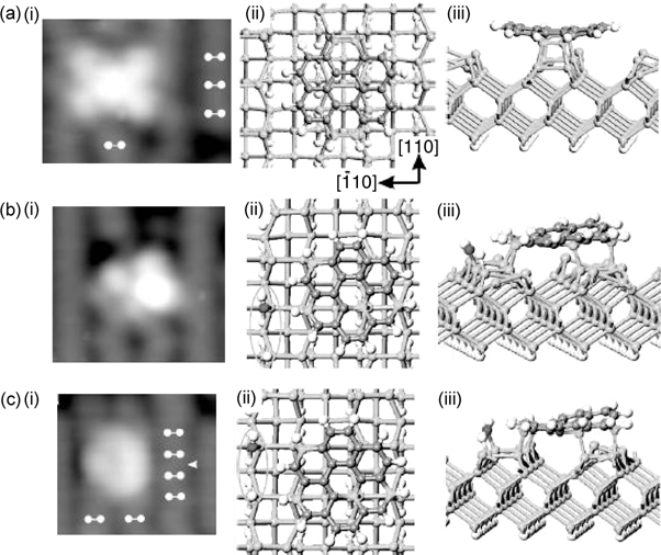
FIGURE 7.9 (i) Experimental STM images and (ii) top and (iii) side views of coronene on Si(100)-(2×1) for (a) major on-top binding mode and (b, c) two minor substrate defect-related binding modes (from Ref. 26).
The other two minor binding configurations are located between dimer rows and near to a type C defect with a dissociated chemisorbed water molecule. Figure 7.9b shows the filled state STM image and the optimized configuration of one of the binding modes. The ellipse in Fig. 7.9b(ii) marks the dissociated water molecule with the darkly shaded ball indicating the oxygen atom. Similar to the on-top binding mode, coronene forms four C–Si bonds with the substrate, but at different dimer rows as marked by the lightly shaded balls, and also possesses a comparable binding energy of 24.2 kcal/mol. The other minor binding species of coronene occupies the same position with respect to the Si dimer rows as the first minor species but differs in the relative position with reference to the dissociated water molecule. This is depicted by the optimized configuration in Fig. 7.9c(ii) and (iii), with the filled state STM image shown in Fig. 7.9c(i). However, the calculated binding energy of 32 kcal/mol is much higher than the previous two configurations, which is attributed to the metallic characteristics of the electronic structure for the type C defect.
7.2.6 Dibenzo[a, j] coronene on Si(100)-(2×1)
Dibenzo[a, j]coronene has a core unit that may be considered as derived from coronene or pentacene. Similar to coronene, dibenzo[a, j] coronene has one major (A) and two minor binding sites (B and C) on the Si(100)-(2×1) surface [27]. The filled state STM image of configuration A (~75% of the total population), with dibenzo[a, j] coronene absorbed on top of the Si dimer rows (indicated by the white makers), is shown in Fig. 7.10a(i). Suzuki et al. associated this binding configuration with the adsorbate having six C–Si bonds with the substrate along the same dimer row. The theoretical structures are depicted in Fig. 7.10a(ii) and (iii), with the carbon atoms that are having chemical bonds with the substrate circled in Fig. 7.10a(ii). Furthermore, it has been shown that the breaking and formation of the C–Si bonds, as indicated by the dotted arrows in Fig. 7.10a(iii), has an activation energy of only 2.3 kcal/mol. Such a low energy barrier suggests the possibility of the interconversion of the two structures at room temperature, whose average structure gives rise to the observed symmetrical STM feature (Fig. 7.10a(i)). The calculated binding energy of this configuration is 26.2 kcal/mol.
The filled state STM image and the optimized structures of configuration B (~15% of the total population) are shown in Fig. 7.10b. Apparently, the adsorbate forms six C–Si bonds (circled atoms in Fig. 7.10b(ii)) with the substrate across two adjacent Si dimer rows and possesses an adsorption energy of 37.5 kcal/mol. This energy is much higher than that for configuration A, which could be attributed to the less pronounced bending of the adsorbate in configuration B. Similar to the major binding mode, dibenzo[a, j] coronene in configuration B could undergo interconversion between two structures via the breaking and formation of C–Si bonds indicated by the dotted arrows in Fig. 7.10b(iii). This is due to the low 0.8 kcal/mol energy barrier for the isomerization to take place. As for configuration C, whose STM image is shown in Fig. 7.10c(i), the adsorbate forms four C–Si bonds with the surface along a Si dimer row as depicted in Fig. 7.10c(ii) and (iii). Due to the lower number of such bonds as compared to the previous two configurations, as well as the pronounced bending of the adsorbate as depicted in Fig. 7.10c(iii), dibenzo[a, j] coronene in configuration C possesses a much lower binding energy of 17.7 kcal/mol.
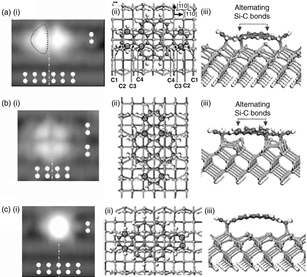
FIGURE 7.10 (i) Experimental STM images and (ii) top and(iii) side views of dibenzo[a, j] coronene on Si(100)-(2×1) for configurations (a) A, (b) B, and (c) C (from Ref. 27).
7.2.7 Acenaphthylene on Si(100)-(2×1)
As shown in Fig. 7.11a, acenaphthylene is made up of an aromatic naphthalene unit that is conjugated to a C=C bond (hereafter referred to as 1,2-alkene). STM study of the adsorption of acenaphthylene on Si(100)-(2×1) indicates that more than 90% of the adsorbates bind through one type of configuration that appears as a bright protrusion centered on a Si dimer row [28]. The exact binding configuration of the molecule was elucidated via FTIR measurement of Si(100)-(2×1) surfaces that were exposed to acenaphthylene or acenaphthylene molecules that were selectively isotopically labeled with deuterium (Fig. 7.11a–c) [28]. The FTIR data indicate that the 1,2-alkene unit of acenaphthylene reacts with a Si dimer via a [2+2]-like cycloaddition with the unreacted naphthalene unit protruding from the surface, as depicted in Fig. 7.11d. This binding configuration has also been shown to be both thermodynamically and kinetically favorable through DFT calculations [29]. Furthermore, the calculation result indicates that it is thermodynamically unfavorable for acenaphthylene to react with the Si dimer via C3 and C4 as well as C11 and C12 at the fusion positions.
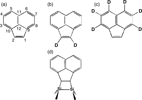
FIGURE 7.11 (a) Acenaphthylene and (b, c) isotopic labeled acenaphthylene used in FTIR study of acenaphthylene adsorption on Si(100)-(2×1) in Ref 28. (d) Binding configuration of acenaphthylene on Si(100)-(2×1) as obtained from FTIR results.
It is interesting to note that the naphthalene unit within the adsorbed acenaphthy-lene retains its aromaticity since only the 1,2-alkene unit is involved in binding to the substrate. In contrast, a large degree of aromaticity is lost for most PAHs when they chemisorb on the Si(100)-(2×1) surface due to the transformations of sp2 carbon atoms within the aromatic unit to sp3 hybridization when they react with the substrate. Hence, the adsorption of acenaphthylene on Si(100)-(2×1) provides a strategy for functionalization or modification of the inorganic silicon surface with the aromatic organic unit.
7.3 PAHs on Si(111)-(7×7)
7.3.1 Naphthalene on Si(111)-(7×7)
Studies done using STM and DFT calculations [30] suggest that naphthalene chemisorbs on Si(111)-(7×7) mainly through the formation of two covalent bonds between C1 and C6 of ring I (or the equivalent C2 and C5 of ring II) and a neighboring adatom and rest atom pair on the substrate. Such a binding mode is denoted as configuration A, as shown in Fig. 7.12b. An STM image of Si(111)-(7×7) with chemisorbed naphthalene is shown in Fig. 7.13. The characteristic feature of at most three adatoms missing within a half unit cell with the three missing adatoms not aligned in a straight line indicates the cooperative binding of naphthalene from an adatom–rest atom pair. The DFT optimized structures of the four possible type A configurations (denoted as configurations A1–A4) are shown in Fig. 7.14a–d. The notations of the clusters are defined in the figure caption.
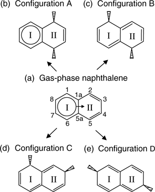
FIGURE 7.12 (a) Sharing of anaromatic sextet within naphthalene based on Clar's sextet concept. (b) Di-σ reactions at ring II of naphthalene produce one sextet in the resulting structure. Reactions at both rings I and II result in configurations (c) B, (d) C, and (e) D of naphthalene on Si(111)-(7×7) that contain conjugated double bonds but no sextet (from Ref. 30).
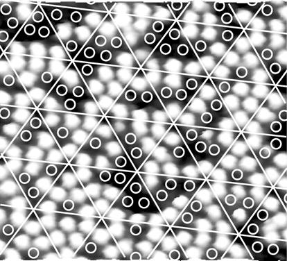
FIGURE 7.13 STM image of Si(111)-(7×7) with adsorbed naphthalene. The superimposed white lines mark out individual half unit cells and each circle indicates a disappeared adatom (from Ref. 30).
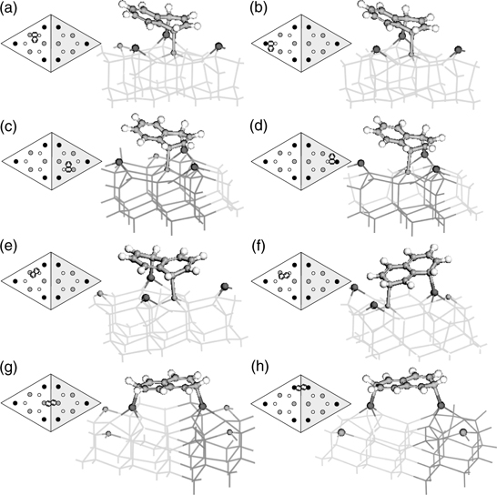
FIGURE 7.14 DFT optimized structures for type (a) A1, (b) A2, (c) A3, (d) A4, (e) B, (f) C, (g) D1, and (h) D2 configurations of naphthalene on Si(111)-(7×7). Notations for each cluster: ball-and-stick, adsorbate; lightly shaded lines, unfaulted half; darkly shaded lines, faulted half; larger and darker shaded spheres, adatoms; smaller and lighter shaded spheres, rest atoms. The schematic diagram on the left of each cluster shows the attachment position of the adsorbate within a (7×7) unit cell, where the shaded and unshaded triangles represent the faulted and unfaulted halves respectively. The center adatoms, corner adatoms, and rest atoms are denoted by the gray, black, and unfilled circles (from Ref. 30).
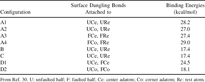
Besides configuration A, other minor di-σ binding modes of naphthalene with the Si(111)-(7×7) surface include configurations B (with bonding at C1 and C5), C (with bonding at C1 and C3), and D (with bonding at C4 and C8). The DFT optimized structures for configurations B–D are shown in Fig. 7.14e–h. In contrast to configurations A–C that bind to an adatom–rest atom pair, configuration D involves the formation of covalent bonds between the farthest two carbon atoms (C4 and C8 which are 5.07 Å apart) with two adjacent faulted and unfaulted adatoms, which are separated by a distance of 6.65 Å. The DFT calculated binding energies of configurations A–D are tabulated in Table 7.1. Apparently, naphthalene in configuration A has the highest adsorption energy followed by configuration D and then configurations B and C. A qualitative approach to comparison of these different binding energies is to utilize Clar's sextet concept [1]. Figure 7.12 shows the aromatic π-conjugation in a free naphthalene molecule and the bonded adsorbates in different configurations. Evidently, only configuration A maintains an aromatic sextet, whose resonance energy contributes to its extra stability as compared to the other configurations. As for configuration D, the planar structure (Fig. 7.14g and h) that allows better π-electron conjugation might account for its higher binding energy as compared to configurations B and C, which suffer greater strain.
TABLE 7.1 DFT Calculated Binding Energy for Each of the Naphthalene Configuration on Si(111)-(7×7) with the Types of Surface Dangling Bonds That are Involved in the Binding Interaction
Despite the higher stability of configuration A, the existence of one or more binding modes for naphthalene on Si(111)-(7×7) depends on their relative activation barriers to formation. Although no kinetic data concerning the formation of the various configurations are available, it is expected that the activation barriers for the production of type B and C species are relatively high. This can be attributed to the energy required for the more extensive breaking of the aromatic π-bonds within naphthalene to form the twisted structure in these binding modes. Therefore, it is proposed that configuration A is the major structure for chemisorbed naphthalene on Si(111)-(7×7). Furthermore, the possibility of naphthalene binding to an adatom–rest atom pair through the carbon atoms at the fusion positions (C1a and C5a) has been shown, via theoretical calculation, to be thermodynamically unfavorable. A possible explanation for the inertness of these ring fused carbon atoms could be the high steric rigidity due to their strong covalent bonding with three adjacent carbon atoms. In contrast, the nonfused carbon atoms bind to two neighboring carbon atoms and one hydrogen atom.
7.3.2 Tetracene on Si(111)-(7×7)
Both STM and DFT have been employed to study the chemisorption of tetracene on the Si(111)-(7×7) surface [31]. Figure 7.15 a and b (with corresponding high-resolution images shown in Fig. 7.15c and d) displays two STM images of the same area of Si(111)-(7×7) that had been exposed to tetracene at sample bias of 1.6 and –2.5 V, respectively. Interestingly, changing of the sample bias resulted in transformations of the surface features from adatoms in (a) and (c) to rest atoms in (b) and (d). Comparison of the missing adatoms (labeled “A”) in Fig. 7.15c and the missing rest atoms (labeled “R”) in Fig. 7.15d found that the “A” and “R” sites correspond to pairs of adatoms and rest atoms that are adjacent to each other. This result provides convincing evidence for the involvement of neighboring adatom–rest atom pairs on Si(111)-(7×7) in binding tetracene, which saturates the Si dangling bonds and causes them to disappear from the STM images.
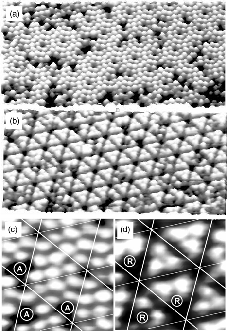
FIGURE 7.15 STM images of tetracene on Si(111)-(7×7) with adatoms visible in the empty state images (a, c) and rest atoms visible in the filled state images (b, d). “A” and “R” indicate the positions of the missing adatoms and rest atoms, respectively (from Ref. 31).
Both experimental [32,33] and theoretical [34,35] studies have shown that the most reactive sites in tetracene for [4+2]-like addition with Si(111)-(7×7) are the meso carbons of the inner rings (namely C2 and C9 or the equivalent C3 and C8)in Fig. 7.16a. These results may be explained qualitatively by Clar's sextet concept [1], as illustrated in Fig. 7.16. Apparently, reactions at the inner rings create species with two sextets located on both sides of the reacted ring (Fig. 7.16b), whereas interactions at the outer rings result in only one sextet that is shared among the remaining three unreacted rings (Fig. 7.16c). Hence, the interaction of tetracene with the Si(111)-(7×7) adatom–rest atom pair is expected to take place at the inner rings II or III to produce adsorbate that is referred to as type “A” configuration.
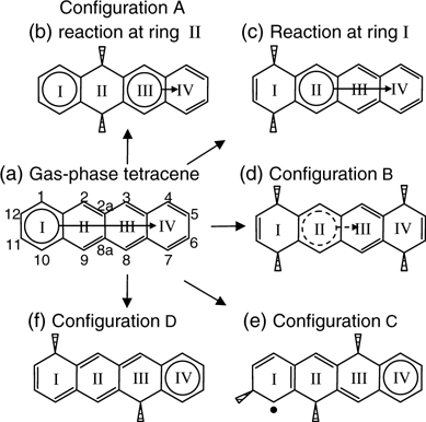
FIGURE 7.16 (a) Sharing of an aromatic sextet within tetracene based on Clar's sextet concept. di-σ reactions at (b) ring II and (c) ring I of tetracene produce, respectively, two and one sextet in the resulting structure. (d) Loss of aromatic sextet due to nonplanar structure in configuration B of tetracene on Si(111)-(7×7). (e) Tetracene in configuration C contains a radical site and possibly a sextet. (f) Reactions at rings I and III in configuration D result in isolation of a sextet to ring IV (from Ref. 31).
The DFT optimized structures of the four possible types of binding modes (referred to as configurations A1–A4) for configurations A are shown in Fig. 7.17a–d, which have the same notation as that used in Fig. 7.14. Apparently, tetracene in configuration A possesses an unsymmetrical butterfly structure that enhances the overlapping of the π-orbitals and in turn the aromaticity on both sides of the reacted ring.
These structures differ from the configuration B of tetracene on Si(100)-(2×1) as proposed by Rada et al. (Section 7.2.2), which involves di-σ reactions between the fused carbon atoms at positions 2a and 8a with the substrate Si dimer. However, DFT calculation indicates that the binding of tetracene to an adatom–rest atom pair via C2a and C8a is thermodynamically unfavorable, in accordance to the theoretical result and explanation as described for naphthalene adsorption on Si(111)-(7×7) in Section 7.3.1.
It is noted that no more than one tetracene in configuration A can bind simultaneously to two or three neighboring center adatoms due to steric hindrance, as illustrated in Fig. 7.18. This figure shows the plan view of three tetracene molecules (one real and two imaginary) adsorbed with configuration A on the unfaulted half of Si(111)-(7×7). The congestion at the central region shows that the dimension of the Si(111)-(7×7) unit cell does not allow the occupations of tetracene adsorbates with type A configuration at two neighboring center adatoms at the same instant. Nevertheless, the disappearance of two center adatoms within a half unit cell has been observed in the STM results, as shown in Fig. 7.19b. It is proposed that such observation is due to tetracene bonded to two neighboring pairs of center adatom–rest atoms via C1 and C10 of ring I and C4 and C7 of ring IV (Fig. 7.19a). Such a binding configuration is feasible as the separation between C1 and C4 (7.42 Å from DFT calculation) is comparable to the distance of 7.68 Å between the two center adatoms. This adsorbate species is referred to as type “B” configuration and consists of B1 and B2 binding modes due to reactions at the unfaulted and faulted halves of the (7×7) unit cell, respectively.
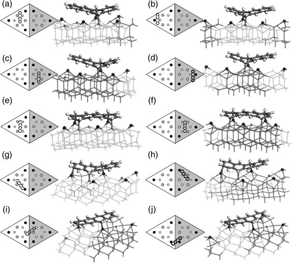
FIGURE 7.17 DFT optimized structures for tetracene binding configurations (a) A1, (b) A2, (c) A3, (d) A4, (e) B1, (f) B2, (g) C1, (h) C2, (i) D1, and (j) D2 on Si(111)-(7×7). The notations are defined the same way as in Fig. 7.14 (from Ref. 31).
The participation of the rest atoms in binding tetracene in configuration B is evidenced from the filled state STM image as shown in Fig. 7.19b(ii). The four circles in the figure denote the adatoms (larger circles) and rest atom (smaller circles) that interacted with tetracene to form covalent bonds. Furthermore, it is apparent that the three neighboring adatoms (marked by the crosses) on an unfaulted half (U) unit cell have greater brightness as compared to the adatoms in the other unfaulted half unit cells that have no reaction. This increase in charge density indicates a transfer of charges from their neighboring rest atoms (the two small circles) so as to facilitate the reaction of these rest atoms, via removal of their excess charges, with tetracene.
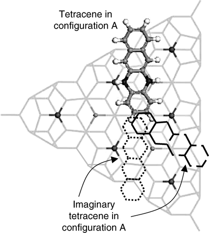
FIGURE 7.18 Cluster model illustrating the adsorption of three tetracene molecules (one real and two imaginary) with configuration A on the unfaulted half of Si(111)-(7×7). The congestion at the central region illustrates the impossibility for two neighboring center adatoms to bind two type A tetracene simultaneously (from Ref. 31).
The DFT optimized clusters for type B1 and B2 configurations are shown, respectively, in Fig. 7.17e and f. Tetracene in these configurations is almost parallel to the surface except for the slight tilt toward the rest atoms due to the approximate 1 Å height difference between the adatom and the rest atom. Furthermore, a sextet that is shared between rings II and III can be identified in these configurations, as shown in Fig. 7.16d. However, it is evident from Fig. 7.17e and f that rings II and III deviate slightly from planarity due to the conversions of the hybridizations of C1, C4, C7, and C10 from sp2 to sp3. The resultant structure would impede the efficient overlapping of the π-orbitals within the sextet and thereby cause a loss in aromaticity.
Overall, configurations A and B adopt almost flat-lying orientations on the substrate, which agree with the conclusion obtained from a NEXAFS study of Si(111)-(7×7) with low coverage of tetracene [36]. Other binding modes such as configurations C and D were proposed as shown in Fig. 7.17g–j. Configuration C involves the formation of three covalent bonds between C3, C9, and C11 of tetracene and the Si dangling bonds at one half of the (7×7) unit cell while configuration D has C1 and C8 bonded to two adjacent adatoms at the border of a faulted and an unfaulted half unit cell. However, the STM results cannot exclusively assign a particular feature to the two binding modes since other configurations could possibly produce a similar feature.
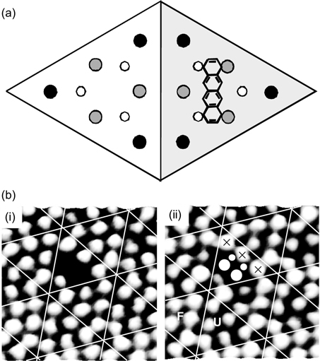
FIGURE 7.19 (a) Schematic diagram and (b) STM images of tetracene with type B binding configuration on Si(111)-(7×7). (b) (i) and (ii) were obtained at Vs = 1.5 and –1.5 V, respectively, with F and U denoting the faulted and unfaulted half unit cells (from Ref. 31).
The DFT calculated binding energies for the various configurations are tabulated in Table 7.2. The presence of four C–Si covalent bonds in configuration B may account for its higher adsorption energy as compared to configuration A, which comprises of only two such bonds. Furthermore, the B1 configuration that is located at the unfaulted half unit cell is slightly more stable than B2 at the faulted half. This is in accordance to Brommer's concept [37], which states that electron-donating species would prefer to react with the center adatoms on the faulted as compared to the unfaulted half. Mulliken charge difference calculation performed on a tetracene adsorbate in B1 configuration points to a charge transfer of ~0.79e from the substrate to the adsorbate. This indicates that tetracene is an electron acceptor with respect to Si(111)-(7×7) and hence is expected to be more stable on the unfaulted center adatoms.
7.3.3 Pentacene on Si(111)-(7×7)
Due to its larger size as compared to naphthalene and tetracene, pentacene exhibits more interesting adsorption configurations on Si(111)-(7×7), as revealed by a combined STM and DFT study [38]. Three types of binding configurations, referred to as configurations A, B, and C, were identified from the STM images. These configurations comprise four C–Si covalent bonds that involve the surface adatoms and rest atoms, in accordance to the results from an XPS study [39]. Figure 7.20 shows the schematic diagram of each of these configurations with their corresponding STM images.
TABLE 7.2 DFT Calculated Binding Energy for Various Tetracene Binding Configuration on Si(111)-(7×7) with the Types of Surface Dangling Bonds That are Involved in the Interaction
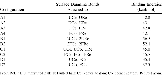
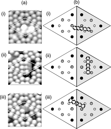
FIGURE 7.20 (a) Empty state STM images and (b) schematic diagrams showing the configurations of pentacene on a Si(111)-(7×7) unit cell for type (i) A, (ii) B, and (iii) C binding modes (from Ref. 38).
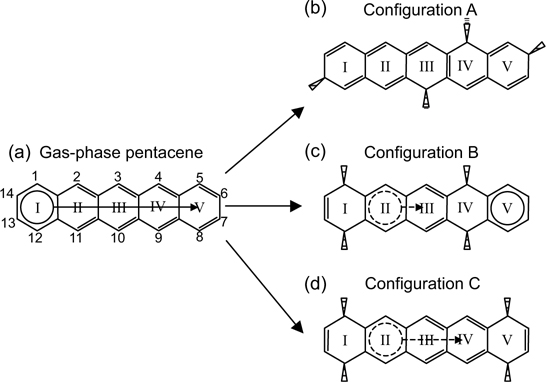
FIGURE 7.21 (a) Sharing of an aromatic sextet within pentacene based on Clar's sextet concept. (b) Pentacene in configuration A contains conjugated double bonds but no sextet. (c) Presence of a sextet at ring V of pentacene in configuration B. (d) Aromaticity loss at rings II, III, and IV due to twisted structure of pentacene in configuration C (from Ref. 38).
From the STM image shown in Fig. 7.20a(i), configuration A appears as two bright spots that are located at specific relative positions across the faulted and unfaulted halves of the unit cell. This binding mode involves a unique engagement of three adatoms and one rest atom on the surface with four carbon atoms of pentacene (C4, C6, C10, and C13) such that the π-conjugation within pentacene is preserved despite a loss in the aromaticity (Figs. 7.20b(i) and 7.21b). The filled state STM image, as shown in Fig. 7.22a(ii), provides direct evidence for the involvement in the surface dangling bonds in the binding reaction. The two spots that are observable in the empty state image (Fig. 7.22a(i)) disappear and adatom vacancies are also seen. The four circles in Fig. 7.22a(ii) indicate the adatoms (three bigger circles) and rest atom (smaller circle) that reacted with pentacene and hence become invisible due to a reduction in the local density of states. Moreover, the involvement of the rest atom is evidenced by the charge transfer from the rest atom to the neighboring corner adatom (marked by the cross) with a consequent increase in its charge density (and hence brightness in the filled state image) as compared to the other two unreacted corner adatoms within the same half unit cell.
The STM image of configuration B is shown in Fig. 7.20a(ii), which is comprised of a dark feature located over two center adatoms within a half unit cell. As depicted in Fig. 7.20b(ii), pentacene in this configuration binds to two center adatom–rest atom pairs within a half unit cell. Similar to the case for configuration A, the participation of the rest atom in the binding reaction can be observed from the filled state STM image as shown in Fig. 7.22b(ii). The two small circles in the figure denote the rest atoms that reacted with pentacene, with consequent charge transfer to their neighboring unfaulted adatoms (marked by the crosses) that achieve the same brightness as the corner adatoms in the faulted half.
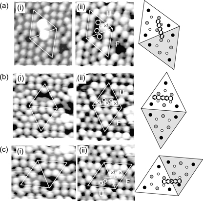
FIGURE 7.22 STM images of pentacene on Si(111)-(7×7) in binding configurations (a) A, (b) B, and (c) C acquired at sample biases of (i) 1.8 V and (ii) –1.8 V. F and U denote faulted and unfaulted half of the unit cell, respectively, and the corresponding schematic diagrams show the attachment positions of pentacene (from Ref. 38).
Figure 7.20a(iii) shows the STM image of pentacene in configuration C, which also appears as a dark feature, but straddles the border between the faulted and unfaulted half unit cell. As depicted in Fig. 7.20b(iii), the two terminal rings of pentacene in this configuration form di-σ-bonds with two oppositely oriented adatom–rest atom pairs located on two different halves of a unit cell. Likewise, the involvement of the rest atoms in the binding reactioncan be verifiedbythe filled state STM image (Fig. 7.22c(ii)). The center adatoms (marked by the crosses) appear unusually bright, which points to an incoming charge transfer from their neighboring rest atoms (marked by the circles) following their reactions with pentacene.
The DFT optimized structures for configurations A, B, and C are shown in Fig. 7.23. Four types of binding modes are possible for configuration A and they are referred to as configurations A1–A4. As depicted in Fig. 7.23a–d, either a combination of three center adatoms plus one rest atom (for A1 and A3 configurations) or one center and two corner adatoms plus one rest atom (for A2 and A4 configurations) take part in binding pentacene in configuration A. Furthermore, the pentacene adsorbate adopts an almost flat-lying orientation on the surface in this configuration.
Figure 7.23 e and f shows the structures for configurations B1 and B2, which are the two possible binding modes for configuration B due to reaction at the unfaulted and faulted halves, respectively. Due to the ~1Å height difference between the adatom and rest atom, pentacene in configuration B is slightly titled toward the rest atoms. This binding mode is the same as that for configuration B of tetracene on Si(111)-(7×7) (Section 7.3.2) since pentacene is made up of a tetracene unit with an additional fused benzene ring. As for configuration C, the two possible binding modes (C1 and C2) are shown in Fig. 7.23g and h. Apparently, pentacene in configuration C is twisted due to the opposite orientation of the two reacted adatom–rest atom pairs as well as the height difference between the adatom and the rest atom.
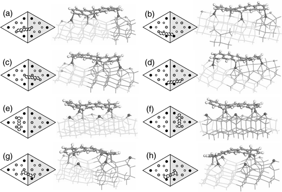
FIGURE 7.23 DFT optimized structures for pentacene binding configurations (a) A1, (b) A2, (c) A3, (d) A4, (e) B1, (f) B2, (g) C1, and (h) C2 on Si(111)-(7×7). The notations are defined the same way as in Fig. 7.14 (from Ref. 38).
TABLE 7.3 DFT Calculated Binding Energy for Various Pentacene Binding Configuration on Si(111)-(7×7) with the Types of Surface Dangling Bonds That are Involved in the Interaction
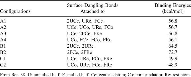
The DFT calculated binding energies for the various configurations are tabulated in Table 7.3, whichcan againbequalitatively compared using Clar's sextet concept [1]. As illustrated in Fig. 7.21b, pentacene in configuration A experiences a complete loss of the aromatic sextet though π-conjugation can still be observed. In contrast, the di-σ reactions at rings I and IV that lead to formation of configuration B would isolate the sextet to ring V (Fig. 7.21c). The possible sextet shared between rings II and III could not be realized due to the deviations of these two rings from planarity (Fig. 7.23e and f), which impede the efficient overlapping of the π-orbitals. Since both configurations A and B possess four C–Si bonds, the extra stability of configuration B could be accounted for by the resonance energy from the aromatic sextet in ring V. As for configuration C, the twisted structures of the adsorbates, as shown in Fig. 7.23g and h, prevent the proper overlapping of the π-orbitals from taking place and hence destroy the aromatic sextet that could be formed and shared among rings II, III, and IV (Fig. 7.21d). Together with the strain induced within the pentacene adsorbate as caused by the twist, it is understandable that pentacene in configuration C possesses the lowest binding energy among the three configurations.
7.4 SUMMARY
Through the use of various experimental techniques combined with theoretical calculations, understanding has been gained on the reactions of PAHs with the Si(100)-(2×1) and Si(111)-(7×7) surfaces. The PAH carbon atoms react with the Si dangling bonds and undergo transformations from sp2 to sp3 hybridization to form C–Si covalent bonds with the substrates. The adsorbates take up configurations that are dependent on their relative dimensions with respect to the positions of the dangling bonds. On the Si(100)-(2×1) surface, the dangling bonds from each dimer pair cooperatively react with the adsorbates, which then adopt orientations that are parallel or perpendicular to the dimer rows. As for Si(111)-(7×7), the adatom–rest atom pair reacts and forms σ-bonds with two opposite carbon atoms from a benzene ring within the PAHs. Additional configurations exist for PAHs with larger dimensions, such as coronene and pentacene, which are able to react with individual dangling bonds from different Si dimer (on Si(100)-(2×1)) or adatom–rest atom (on Si(111)-(7×7)) pairs.
The binding energies of the various configurations differ and depend on the number of C–Si covalent bonds as well as the degree of π-conjugation or aromaticity in the resultant structures. In general, adsorbates with larger extent of bending or twisting have a reduced amount of π-orbital overlap and hence lower binding energies. The strong interactions between PAHs and the silicon surfaces lead to the almost flat-lying orientations of the adsorbates typically observed, though perylene was found to adopt a standing orientation on Si(100)-(2×1). It is also interesting to note that acenaphthylene chemisorbs on Si(100)-(2×1) via the 1,2-alkene unit and leaves the aromatic naphthalene unit unperturbed. Such atomistic understanding of the reaction mechanisms and binding configurations of PAHs on the silicon substrates contribute to knowledge of semiconductor surface science as well as research in the areas of organic-inorganic hybrid devices, organic electronics, and molecular electronics.
REFERENCES
1. (a) Clar, E. Polycyclic Hydrocarbons, Vols. 1 and 2. Academic Press, London, 1964. (b) Clar, E. The Aromatic Sextet. Wiley, London, 1972.
2. Shaw, J. M.; Seidler, P. F. IBM J. Res. Dev. 2001, 45, 3.
3. Bendikov, M.; Wudl, F.; Perepichka, D. F. Chem. Rev. 2004, 104, 4891.
4. Mabrook, M. F.; Yun, Y.; Pearson, C.; Zeze, D. A.; Petty, M. C. Appl. Phys. Lett. 2009, 94, 173302.
5. Pandey, A. K.; Nunzi, J.-M. Appl. Phys. Lett. 2006, 89, 213506.
6. Muccini, M. Nat. Mater. 2006, 5, 605.
7. Choi, J.-M.; Lee, J.; Hwang, D. K.; Kim, J. H., Im, S. Appl. Phys. Lett. 2006, 88, 043508.
8. Shao, Y.; Sista, S.; Chu, C.-W.; Sievers, D., Yang, Y. Appl. Phys. Lett. 2007, 90, 103501.
9. Filler, M. A.; Bent, S. F. Prog. Surf. Sci. 2003, 73, 1.
10. Cornil, J.; Beljonne, D.; Calbert, J.-P.; Brédas, J.-L. Adv. Mater. 2001, 13, 1053.
11. Okamura, K.; Ishii, H.; Kimura, Y.; Niwano, M. Surf. Sci. 2005, 576, 45.
12. Okamura, K.; Hosoi, Y.; Kimura, Y.; Ishii, H.; Niwano, M. Appl. Surf. Sci. 2004, 237, 439.
13. Rada, T.; Chen, Q.; Richardson, N. V. J. Phys. 2003, 15, S2749.
14. Rada, T.; Chen, Q.; Richardson, N. V. Phys. Status Solidi b 2004, 241, 2353.
15. Mao, H.; Guan, D.; Chen, M.; Dou, W.; Song, F.; Zhang, H.; Li, H.; He, P.; Bao, S. J. Chem. Phys. 2009, 131, 044703.
16. Kasaya, M.; Tabata, H.; Kawai, T. Surf. Sci. 1998, 400, 367.
17. Hughes, G.; Roche, J.; Carty, D.; Cafolla, T.; Smith, K. E. J. Vac. Sci. Technol. B 2002, 20, 1620.
18. Weidkamp, K. P.; Hacker, C. A.; Schwartz, M. P.; Cao, X.; Tromp, R. M.; Hamers, R. J. J. Phys. Chem. B 2003, 107, 11142.
19. Okamura, K.; Hosoi, Y.; Kimura, Y.; Ishii, H.; Niwano, M. Appl. Surf. Sci. 2004, 237, 439.
20. Suzuki, T.; Sorescu, D. C.; Yates, J. T., Jr. Surf. Sci. 2006, 600, 5092.
21. Lee, H.-K.; Han, J.-H.; Kim, K.-J.; Kang, T.-H.; Kim, B. Surf. Sci. 2007, 601, 1456.
22. Yamaguchi, T. J. Phys. Soc. Jpn. 1999, 68, 1321.
23. Choudhary, D.; Clancy, P.; Bowler, D. R. Surf. Sci. 2005, 578, 20.
24. Nunzi, F.; Sgamellotti, A.; Coletti, C.; Re, N. J. Phys. Chem. C 2008, 112, 6033.
25. Preuss, M.; Miotto, R.; Bechstedt, F.; Rada, T.; Richardson, N. V.; Schmidt, W. G. Phys. Rev. B 2006, 74, 115402.
26. Suzuki, T.; Sorescu, D. C.; Jordan, K. D.; Levy, J.; Yates, J. T., Jr. J. Chem. Phys. 2006, 124, 054701.
27. Suzuki, T.; Sorescu, D. C.; Jordan, K. D.; Yates, J. T., Jr. J. Chem. Phys. 2006, 124, 224708.
28. Schwartz, M. P.; Halter, R. J.; McMahon, R. J.; Hamers, R. J. J. Phys. Chem. B 2003, 107, 224.
29. Nunzi, F.; Sgamellotti, A.; Re, N. J. Phys. Chem. B 2004, 108, 10881.
30. Yong, K. S.; Zhang, Y. P.; Yang, S.-W.; Xu, G. Q. Surf. Sci. 2008, 602, 1921.
31. Yong, K. S.; Zhang, Y. P.; Yang, S.-W.; Wu, P.; Xu, G. Q. J. Phys. Chem. A 2007, 111, 12266.
32. Biermann, D.; Schmidt, W. J. Am. Chem. Soc. 1980, 102, 3163.
33. Murata, Y.; Kato, N.; Fujiwara, K.; Komatsu, K. J. Org. Chem. 1999, 64, 3483.
34. Schleyer, P. v. R.; Manoharan, M.; Jiao, H.; Stahl, F. Org. Lett. 2001, 3, 3643.
35. Cheng, M. F.; Li, W.-K. Chem. Phys. Lett. 2003, 368, 630.
36. Schedel, Th.; Frank, K.-H.; Karisson, U.; Koch, E. E. Vacuum 1990, 41, 652.
37. Brommer, K. D.; Gálvan, M.; Dal Pino, Jr., A.; Joannopoulos, J. D. Surf. Sci. 1994, 314, 57.
38. Yong, K. S.; Zhang, Y. P.; Yang, S. W.; Wu, P.; Xu, G. Q. J. Phys. Chem. C 2007, 111, 4285.
39. Hughes, G; Carty, D.; Cafolla, A. A. Surf. Sci. 2005, 582, 90.
Functionalization of Semiconductor Surfaces, First Edition
Edited by Franklin (Feng) Tao and Steven L. Bernasek.
© 2012 John Wiley & Sons, Inc. Published 2012 by John Wiley & Sons, Inc.