
CHAPTER 5
Fixed Ham Stations
Imagine that you just got your General Class license and bought some equipment for a station. You have a transceiver, an antenna tuner, a computer, and an interface unit that’ll let you use some of those fancy digital modes on the HF bands! You’ve unpacked the equipment from the boxes. You’ve obtained all the interconnecting cables that you’ll need, and you’re ready to put it all together and get on the air.
Where Will You Put Your Rig?
Where in your home do you want your rig to reside? You have several choices from the basement to the top floor.
The Electrical System
Before you decide where to put your new ham radio station, you’ll want to make sure that you can get enough electricity to the equipment. If you have a low-power or medium-power transmitter (150 watts output or less) and a notebook computer, you’ll do okay with a common utility outlet on a circuit rated at 15 or 20 amps. In the United States, the standard AC utility provides 117 volts, give or take a few percent, so 15 amps would give you the ability to power a rig that demands up to 117 volts × 15 amps = 1755 volt-amps. That’s around 1600 or 1700 watts, assuming that you don’t connect anything else to the circuit. You can find outlets like that just about anywhere these days.
If you want to run high power and use an outboard RF power amplifier (called a linear amplifier, or simply a linear), you’ll want to have a 234-volt circuit for your rig, rather than a 117-volt circuit. The higher voltage circuits take advantage of both components of the split-phase electrical system that most homes have in the United States. You’ll get twice the power for the same number of amps, and you’ll get a more stable voltage as well.
Whether you go for a 117-volt system or a 234-volt system, make sure that the power line has a good electrical ground connection. That means you’ll need outlets with three slots as well as power cords with three conductors and three prongs in their plugs. If you have a 117-volt installation, you can add a power strip with a transient suppressor (sometimes mistakenly called a “surge protector”) and a 15-amp breaker. Then, once you have met all those requirements, you must make sure that the ground slot in your outlet actually goes to the household ground.
People often assume that a three-wire 117-volt utility outlet has a good ground at its “third hole” (the bottom hole, not either of the vertical slots). That’s not always true. I’ve seen outlets in which that “third hole” wasn’t connected to anything! You can use a long extension cord and a volt-ohm-milliammeter (VOM), also called a multimeter, to find out whether or not a particular three-wire 117-volt outlet has a good electrical ground at its “third hole.” Go through the following steps using Fig. 5-1 as a reference. If you want this test to work, you’ll have to find a reference outlet in your house that you know has a good ground at its “third hole.”
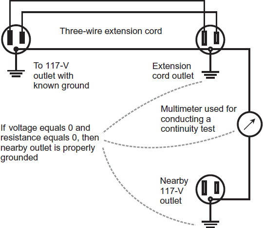
FIGURE 5-1 Arrangement for determining whether the “third prong” of an outlet actually goes to electrical ground. Follow the procedure for a continuity test. Always check for voltage before measuring resistance! Wear your gloves at all times.
1. Put on a pair of rubber gloves and a pair of shoes with soles that will electrically insulate your feet from the floor.
2. Plug a long three-wire extension cord into an outlet with a known electrical ground at the “third hole.”
3. Locate the outlet end of the extension cord next to the outlet whose “third hole” you want to test.
4. Set your multimeter to measure the highest AC voltage that it can deal with.
5. Insert the multimeter’s black (negative) probe tip into the “third hole” in the extension cord outlet.
6. Insert the multimeter’s red (positive) probe tip into the “third hole” of the outlet you want to test, while leaving the black probe tip in the extension cord outlet.
7. Check the meter reading. If it shows anything other than 0, then an AC voltage exists between the two points, so your outlet does not have a good ground. It will present a shock or fire hazard if you use it.
8. If you see 0 as the result for step 7, switch the meter to the next lower AC voltage function and repeat the test.
9. If you get 0 again, repeat steps 8 and 9 with all the AC voltage functions that the meter has, going down until you’ve tested at the lowest AC voltage setting. You should always get a reading of 0. If you don’t, then you know that some AC voltage exists between the two points, so your outlet does not have a good ground.
10. Assuming that you’ve seen readings of 0 for all the AC voltage settings, repeat the tests with your multimeter’s DC voltage settings, starting with the highest one and working your way down to the lowest one. Test for DC voltage in both directions: first with the black probe tip in the “third hole” of the cord outlet and the red probe tip in the “third hole” of the outlet under test, and then the other way around. You should always see a meter reading of 0.
11. If you ever see any DC voltage besides 0 between the two points, then you know that your outlet does not have a good ground.
12. If you see 0 for all of the AC and DC voltage results, switch your multimeter to the highest resistance function.
13. Touch the meter’s two test probe tips to each other. If you’re using an analog meter, tweak the “0ΩADJ” knob so that the meter indicates 0. If you’re using a digital meter, make sure that the display indicates a value of 0.
14. Insert the black probe tip back into the extension cord’s “third hole,” and the red probe tip back into the outlet’s “third hole.” You should get a reading of 0.
15. Reverse the test leads. You should again get a reading of 0.
16. Repeat steps 13 through 15 for all the rest of the meter’s resistance settings, working your way down one setting at a time, until you get to the lowest one.
17. If you have observed readings of 0 for every step in the foregoing process, then you can have confidence that your outlet’s “third hole” is properly grounded.
18. If you ever see any meter reading other than 0 for the condition between the two “third holes,” you know that your outlet does not have a good ground. In that case, treat it as a two-wire outlet until you can get a professional electrician to wire it up properly.
Warning! If the “third hole” in an outlet connects to a wire that isn’t grounded, that wire can pick up stray AC by electromagnetic induction from other wires in your house, giving you a potentially lethal shock. It can also cause sensitive electronic equipment to malfunction. It can increase the likelihood of, or worsen, any preexisting problems with “RF in the shack.” In addition to all that, if you connect a transient suppressor into the circuit, it won’t protect anything because it will have no ground to “work against.”
Always strive to provide your radios with a steady line voltage. You can tell if the voltage fluctuates under load by connecting an old-fashioned incandescent lamp to the same circuit as your rig. Does the lamp dim when you key up? If so, you need a more robust electrical supply! If you want to get more technical, you can actually hook up an AC voltmeter to your system and watch its reading as you key the rig on and off.
Your choice of rig location will be limited if you want to “run the max” and operate in so-called QRO (high power) mode. You might even need to have an electrician come to your home and install a 234-volt system at the place where you plan to build your station. If you plan to use a minimum amount of power for your station, you won’t need to worry about all that electrical business.
Basement
Whenever I’ve lived in a full-sized house, I’ve located my ham radio equipment in the basement. It seems like the natural place for a hobby like this. There’s something about the ambience of a typical basement that lends itself to nerdy activities like ham radio, especially the technical and experimental variety in which I engage. Of course, if you live in a condo or an apartment, or if you live in a part of the country where basements don’t work (South Florida, for example), you don’t have this option. But it’s the one I recommend if you can manage it.
If you opt for the basement, you’ll have to figure out how to get your antenna feed line or lines into the radio room (which hams call the shack, even if it’s an elegant dedicated bedroom or den). That’s more difficult for below-ground stations, obviously, than for above-ground stations. When I was first licensed at age 12, my rig went in the family fallout shelter, which my parents had built after the Cuban missile crisis. Mom and Dad didn’t want me to drill holes through the concrete blocks for antenna feed lines. So I had to run the feed line around the winding hallway that led into the place, and out into the furnace room, and up through the outside wall of the house just above ground level. That route necessitated a long feed line—over 150 feet of coaxial cable to a 7-MHz dipole 10 feet off the ground. I’d have done better with an open-wire feed line, but it wouldn’t have worked with all those bends and nearby copper pipes.

First Floor
The first floor offers several advantages for fixed ham radio stations. You can get a fair RF ground for end-fed, random wires from there by running a wire out a window and connecting it to a ground rod. In addition, the first floors of homes have windows, so you can easily run your feed lines, ground wires, and control cables outside! If you can manage to get your operating desk or table underneath a window, you’ll have the best of everything.
The first floor is the most common place for small “dens,” which serve well as ham radio zones. If you’re married, your spouse might take exception to your demanding an entire room for your radio station, but then again, maybe she (or he) will be happy that you don’t want to put that geeky gear out in plain sight, where house guests will see it and cats will make mischief with it. A spare bedroom is another good place for a ham station. Failing all that, you can put it in a corner of the living room.
If your home has an old-fashioned up-and-down sliding window and you can get your radio next to it, you can run feed lines and other wires through the opening using the scheme shown in Fig. 5-2. Get a piece of lumber that has the same thickness as the depression at the base of your window sash. Cut the piece of lumber to a length that equals the inside width of the sash. Then drill holes in the wood, having the correct diameters for your cables and other wires, and thread those cables or wires through the holes (before you install cable or wire connectors, of course). Remove any existing external screen or storm window. Open the window, set the wood with the cables down in the base of the sash, and then close the window, sliding it firmly down to hold the wood in place.
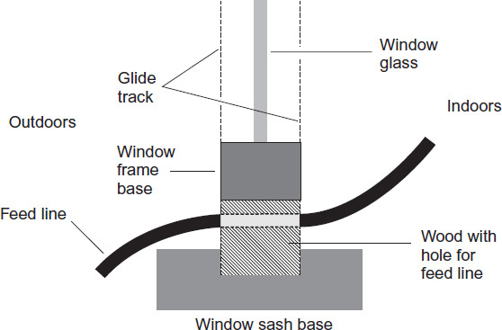
FIGURE 5-2 You can put a strip of wood at the base of an up-and-down sliding window and run feed lines and ground wires through it. You’ll have to remove any existing external screen or storm window.
Many hams use transmitters that put out only 100 or 150 watts, so they opt for an end-fed, random wire as the antenna. (If you plan to run the legal limit, an end-fed, random wire will probably give you trouble with “RF in the shack.”) When tuned with a good transmatch (antenna tuner), an end-fed random wire offers decent performance on any band for which it measures at least an electrical quarter wavelength long. In addition, such an antenna can have a low profile if you use small gauge wire. Unless people know that the antenna exists, they might never even notice it, especially if you can get it up into trees.
Any end-fed wire, no matter how long or short, needs a good RF ground at its feed point. A ground rod by itself won’t suffice unless you live in a salt flat or swamp where it rains often! You can enhance the RF performance of your ground system by burying quarter-wavelength radial wires about a foot (30 centimeters) under the surface of your yard. Run them out at various angles. Figure 5-3 shows a hypothetical example for a modest-sized yard. It doesn’t matter whether or not the wire has insulation. The ground rod should go down at least 8 feet (2.4 meters), though, and be about 3 feet (1 meter) away from the house foundation.
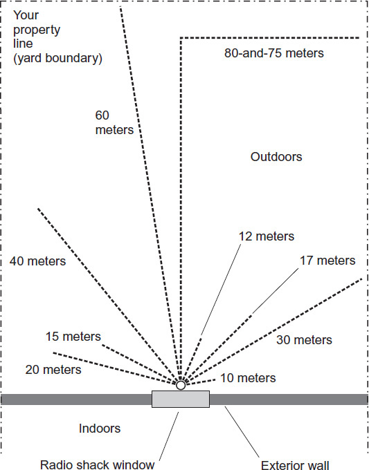
FIGURE 5-3 Simple method of getting an RF ground for an end-fed, random wire when your station is next to a first-floor window. The small open circle represents the ground rod; heavy dashed lines represent quarter-wavelength buried radials.
Upper Floors
If you put your station on a floor above ground level, then you’ll have trouble making the ground scheme of Fig. 5-3 work for an end-fed wire. You’ll have to run a significant length of wire from your rig to the ground rod, and that wire will act as part of your antenna! The problem might not cause too much trouble at the lowest frequencies (1.8 MHz and 3.5 MHz), but it will affect performance at higher frequencies. If your station has to go above ground level, then, you’re better off with an antenna with the feed point located a good distance away from your station. That means you’ll have to use a transmission line between your radio and your antenna.
Although you can’t expect to get a good RF ground from the station location on an upper floor, you can still get a good RF ground for your whole system if you put it at the feed point for, say, a ground-mounted, vertical antenna. A dipole antenna fed with a balanced open-wire line doesn’t need a dedicated RF ground, nor does a Yagi or other well-designed antenna fed with coaxial cable. These antennas, in effect, supply their own RF ground at the feed point. Nevertheless, you’ll always want to ensure that your rig has a substantial electrical ground, so that you don’t get a shock from metallic parts in the event of a short circuit in the equipment somewhere.
The “Main Radio”
Some hams prefer separate transmitters and receivers, especially on the HF bands, for the “main radio.” However, latter-day transceivers have gained many of the features once available only with separate units. Let’s look at the basic functions and features of a typical transceiver of the sort you can get from brand-name vendors.
Overview
Fixed-station radios have power supplies that let them work directly from the 117-volt or 234-volt AC household utility mains. You can categorize these radios according to their frequency coverage. Numerous models cover 160 through 10 meters. Many, if not most, have receiving capability continuously throughout the HF range, and some can receive as low as a few kilohertz and as high as several hundred megahertz. In a good radio, a microcomputer limits transmitting capability to the ham bands only.
Most transceivers for HF can work all popular modes including CW, SSB, AM, FM, and the various digital modes by means of audio data supplied to the microphone input when you set the rig to work on SSB. Units designed for VHF and UHF might cover one band, such as 2 meters, or two bands, such as 2 meters and 70 centimeters. A few can cover several bands. Some work only on FM, while others can work all popular modes including CW, SSB, AM, and the digital modes.
Common Features
You can acquaint yourself with all the features available in modern ham transceivers by going to a hamfest (organized convention of ham radio operators) and looking at radios, or by obtaining specific model brochures from manufacturers. Nearly all radios these days, especially the ones designed for HF use, have the following features:
• Digital frequency displays use seven-segment LED or LCD modules to give you a direct numerical readout of your frequency. While a digital display has obvious assets, a few operators prefer analog displays that “slide along as you tune.” These days, digital displays are practically a cosmic standard, so if you’re an “analog tuning addict,” you might want to shop for a vintage radio at a hamfest or convention!
• A precision readout displays your frequency to the nearest tenth of a kilohertz, and sometimes down to a hundredth of a kilohertz (10 Hz), from 160 through 10 meters. You’ll rarely see this resolution level of VHF/UHF, but some radios have it all the way from the lowest coverage frequency to the top.
• Longwave coverage lets you listen all the way down to 100 kHz, 30 kHz, or even 10 kHz in some radios.
• Flywheel tuning, in which a rotatable frequency control system acquires physical momentum when you turn it, gives the control a substantial “feel.” You can rapidly carry out several revolutions of the knob with a single sharp twist; the dial keeps on going for a second or so after you let it go. Many operators like flywheel tuning, but some do not. If possible, check out some radios “live” at a hamfest or convention to evaluate them in this respect and decide whether or not you like the “feel.”
• Continuous receive coverage allows you to listen all the way from the lowest design frequency to the highest, without any gaps.
• A preamplifier is a low-noise amplifier intended for boosting weak signals. It can improve the sensitivity of a receiver at the front end, but it’s important that linearity be as good as possible. Nonlinearity gives rise to a wide variety of problems, especially if you use the preamplifier when some of the signals are strong. A receiver with a built-in “preamp” should allow you to switch it off when you don’t need it.
• A noise blanker blocks the receiver for a few milliseconds when a noise impulse comes in. This type of circuit can be extremely effective against ignition noise in some cases, but doesn’t do much for “thunderstorm static” or some forms of electrical line noise. In any case, you should always look for this feature when shopping for a radio.
• Rectangular response—A good IF bandpass filter exhibits a so-called rectangular response. In theory, a rectangular response is characterized by zero attenuation inside the passband and infinite attenuation outside the passband. Look for radios that approach this ideal as closely as possible. You can figure out how well a receiver performs in this respect by looking at the shape factor specification (page 152) or, better yet, testing a radio in real time.
• Band scanning—In a channelized receiver such as you’ll often find at VHF and UHF, band scanning can save you a lot of tedious tuning and hunting for signals. You can program the radio to constantly sweep through a given span of frequencies (the limits for which you can program into the radio’s microcomputer) until it encounters an occupied channel.
• Channel scan—In some radios for use on any ham band from 160 meters through microwaves, you can scan through a preselected set of channels stored in memory. This mode is known as channel scan. Some radios can search for either a vacant frequency or an occupied frequency.
• Programmable memory allows you to store certain frequencies and call them up later at the push of a button, without the need for changing the band switch or VFO setting. You’ll find this feature in contemporary radios for use on any of the ham bands.
• Receiver incremental tuning (RIT) lets you adjust the receiver frequency a few kilohertz up or down from the transmitter frequency, which remains constant as determined by the main variable frequency oscillator (VFO) or synthesizer. This feature is especially popular among contesters and DXers on the HF bands.
• Dual VFOs allow the receiver and transmitter frequencies to be determined independently within a given band, or, in some units, in crossband mode (transmit and receive frequencies in different amateur bands).
• Semi break-in operation in CW actuates the transmitter automatically when the key is closed; the receiver is disabled with a delay.
• Full break-in operation, also known as full QSK, lets you hear signals in between the dots and dashes of CW transmissions, and in some radios, between words or syllables of speech in SSB.
• Auto-tune function gets rid of the need to manually tune the transmitter’s final amplifier when you change frequency.
• A built-in CW keyer lets you connect a key paddle (such as the Vibroplex Vibrokeyer, my all-time favorite!) to the radio directly, without having to purchase an outboard electronic keyer box.
Advanced Features
Sophisticated radios have capabilities that can help you with contesting, traffic handling, specialized modes, and DXing (seeking out contacts with stations in exotic locations).
• Delta tuning allows you to adjust the receiver frequency alone, or the transmitter frequency alone, for up to several kilohertz either side of the main VFO frequency. It is, in effect, incremental tuning that works with either the receiver or the transmitter. This feature is popular in DXing. Many DX station operators want you to call on a frequency other than their own transmitting frequency.
• Panoramic reception allows you to visually monitor a specified band of frequencies. A small screen displays the signals as vertical pips along a horizontal axis. The signal amplitude is indicated by the height of the pip. The position of the pip along the horizontal axis indicates its frequency. Usually, your frequency appears at the center of the horizontal scale.
• An adjustable IF passband compensates for the fact that different modes occupy different signal bandwidths. A CW receiver works well with an IF bandwidth of 500 Hz, while for SSB, an IF bandwidth of 2.7 kHz is typical. In high-noise or crowded band conditions, narrower IF bandwidth can improve the sensitivity. Advanced radios have programmable passbands, and some let you adjust the shape factor (described under “Specifications”) too!
• An automatic noise limiter clips noise (QRN) peaks, while not affecting the desired signal. The circuit sets the clipping threshold according to the strength of the incoming signal. A limiter prevents noise from getting stronger than signals within the receiver passband. This scheme will sometimes help you hear signals through noise that defeats a standard noise blanker.
• An audio passband filter can enhance reception above and beyond the performance obtainable with IF filtering alone. A filter with a passband going from 300 Hz to 3000 Hz can improve the quality of reception in SSB. A CW signal needs only about 100 Hz of bandwidth in order to be clearly read at most speeds that hams use. Some CW audio filters can cut the bandwidth down to 50 Hz or less for reception at slow speeds under exceptionally adverse conditions.
• A notch filter is a band-rejection filter with a sharp, narrow, tunable response. By adjusting the notch frequency, you can null out interfering heterodynes (carriers that produce audio tones with a product detector). This feature can prove invaluable on bands that hams must share with shortwave broadcasting, such as the upper end of 40 meters.
• Mechanical filters and ceramic filters are IF bandpass filters found in a few high-end, vintage, dual-conversion receivers with low-frequency, second IF chains, notably the old Collins Radio equipment. These filters rival today’s digital signal processing (DSP) for performance. The input signal gets converted into electromechanical vibration by the input transducer. The resulting vibrations travel through a set of resonant disks to the output transducer. The output transducer converts the vibrations back into an electrical signal.
• Q multiplier—In early superheterodyne receivers, a circuit called a Q multiplier was occasionally used to enhance the selectivity. You’ll still find such circuits in some vintage radios, along with ceramic and mechanical filters. In today’s radios, DSP has pretty much taken over the IF filtering job.
• Standing-wave ratio—A good high-end radio will have a wattmeter at the antenna terminals so you can see how much RF power your transmitter puts out at any given time. Some of these meters also give you an indication of the standing-wave ratio (SWR) at the transmitter antenna terminals. Caution: Poorly designed or cheap wattmeters give accurate readings only when the SWR is 1:1 with a 50-ohm coaxial feed line (indicating a perfect impedance match between the line and the antenna).
• Weight controls—High-end radios with built-in electronic keyers sometimes have CW weight controls to compensate for the varying tastes of receiving operators, and for the effects of high speed on the signal envelope. A typical weight control allows adjustment of the dot-to-space ratio between limits of about 1:2 (“light”) and 2:1 (“heavy”).
Specifications
In addition to looking over the features that various radios have to offer, you’ll want to know how well they do their job. You must “dig around” to get this information; product reviews (especially the ones in QST, the official magazine of the ARRL) can help you out. The manufacturer’s technical data brochures or sheets will give you information as well.
• Front-end specifications get more important as the frequency gets higher, and attain paramount significance at VHF, UHF, and microwave frequencies. The front-end amplifier must be as linear as possible, and should be capable of handling very strong as well as very weak signals. If a receiver has a front end that can’t handle strong signals, desensitization (a momentary loss of sensitivity) will occur when a strong signal comes in at the antenna terminals.
• Noise figure is a specification of the performance of an amplifier or receiver. This figure, expressed in decibels, tells you how much a circuit deviates from the theoretical ideal. The noise figure is important at VHF, UHF, and microwave frequencies, where relatively little noise occurs in the external environment, and the internal noise, therefore, limits the sensitivity. Look for the lowest possible number.
• Noise quieting is an expression of the noise reduction in an FM receiver as a result of an incoming signal. With the squelch open and no signal, the receiver emits a hiss because of internally generated noise. When a weak signal comes in, the noise level decreases. As the signal gets stronger, the level of the noise continues to decrease. This phenomenon provides a means of measuring the sensitivity of an FM receiver. You measure the level of the noise at the speaker terminals under no-signal conditions. Then you introduce an unmodulated signal with a calibrated generator. You increase the signal strength until the noise voltage drops by 20 dB at the speaker terminals. Then you measure the signal level, in microvolts, at the antenna terminals. When shopping for a radio, look for the lowest possible microvolt figure associated with 20 dB of noise quieting (NQ).
• SINAD is an acronym based on the technical expression “signal to noise and distortion.” The SINAD figure is frequently used to define the sensitivity of an FM receiver at VHF and UHF. It takes into account not only the NQ sensitivity of a receiver, but also its ability to reproduce a weak signal with minimum distortion.
• The squelch sensitivity of a VHF or UHF FM receiver is the signal level, in microvolts at the antenna terminals, needed to keep the squelch open continuously. Squelch sensitivity is related to noise-quieting sensitivity. The better the quieting sensitivity, the less signal it takes to actuate the squelch at the threshold. Look for the lowest possible value, expressed in microvolts at the antenna terminals.
• Dynamic range is the ratio, in decibels, between the levels, in microvolts, of the strongest signal that can exist at the antenna terminals without causing appreciable distortion in the front end, and the weakest signal that the radio can bring in. Most receivers today have adequate sensitivity, so that’s not a primary limiting factor in the dynamic range of a receiver. Much more important is the ability of a receiver to tolerate strong input signals without developing nonlinearity. Look for the highest possible decibel figure.
• Image rejection—In a poorly designed receiver, you’ll hear lots of phantom signals, called images, on frequencies where they really aren’t transmitting. Image rejection is the extent to which images are attenuated with respect to a signal on the desired frequency. Image rejection is specified in decibels. In general, the higher the intermediate frequency of a receiver, the better the image rejection. Look for the highest possible number.
• Intermodulation spurious-response attenuation is expressed in decibels. It’s an alternative way to express image rejection. The susceptibility or immunity of a receiver to spurious responses is primarily dependent on the design of its front end. Look for the highest possible decibel figure.
• Harmonic suppression is the degree to which harmonic energy is attenuated, with respect to the fundamental frequency, in the output of a radio transmitter. Emitted harmonics can cause interference to other services and operations. The FCC regulates the behavior of commercially manufactured transmitters in this respect. You’ll see the figure given in decibels. Look for the highest possible number.
• Shape factor—In a receiver, the shape factor expresses how close the IF bandpass filter comes to having a rectangular response. It’s determined by measuring the passband width for two attenuation levels such as −6 dB and −60 dB, and then dividing the latter number by the former. The smaller the result, the better. A perfect rectangular response would correspond to a shape factor of 1:1, or simply 1.
Peripheral Equipment
Many ham radio operators get by with a transceiver, a headset, and a microphone for their home station use. If that’s all you need to start out with, that’s fine, but sooner or later you’ll probably want to add more stuff. Popular peripherals include linear amplifiers, transmatches (also called antenna tuners), and digital interface equipment.
Linear Amplifier
A linear amplifier or “linear” is an RF power amplifier that faithfully reproduces the modulation envelope of an SSB or AM signal. Linears can function with amplitude, frequency, phase, or pulse modulation. A linear will not, when operated properly, introduce significant distortion into the signal, no matter what type of emission the driving signal has.
Linears have always been popular among DXers and contesters. They have also proven valuable in traffic handling, especially when the traffic has a priority or emergency nature, and you want to ensure that your messages reach their destinations in the shortest time possible, without having to repeat yourself because of interference or marginal band conditions.
A commercially manufactured linear usually comes from the vendor as a self-contained unit, sometimes with a built-in power supply and sometimes with an outboard supply. The most rugged linears can provide 1500 watts continuous (100-percent duty cycle) RF output, the maximum legal limit for amateur service. Some linears are designed to supply 1500 watts output for a 50-percent duty cycle, typical CW and SSB. Other linears can’t provide the maximum legal limit but instead go with something less, such as 700 watts or 1000 watts. These units might work for hams on a strict budget, or who do not have access to the recommended 234-volt AC utility panel that a full-power linear should have.
Today’s linears have features that make them versatile indeed compared to their “boat anchor” ancestors! These attributes can include built-in wattmeters, built-in SWR meters, provisions for full CW break-in option, automatic shutdown in case of overheating, automatic gain control (AGC), and automatic tune-up or broadband operation.


Figure 5-4 is a simplified schematic diagram of a scaled-down, broadband linear that operates with a single power transistor. Larger linears (providing more power) have essentially this same configuration, but might need two or three large power transistors connected in parallel.
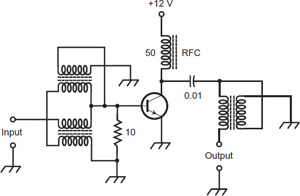
FIGURE 5-4 A broadband RF power amplifier, capable of producing a few watts of output. Resistances are in ohms. Capacitances are in microfarads (µF). Inductances are in microhenrys (µH). The 50-µH component labeled “RFC” is an RF choke.
Transmatch
The output impedance of a radio transmitter, or the input impedance of a receiver, should ideally be matched to the antenna-system impedance. This state of affairs requires that the antenna system present a nonreactive load (no capacitance or inductance, but only the esoteric phenomenon known as radiation resistance) of a certain value, usually 50 ohms. Very few antenna systems meet this requirement to perfection, but you can match almost any load impedance to your radio by means of a transmatch, which comprises inductors and capacitors that cancel out the antenna’s reactance and convert the remaining resistance to the appropriate value to provide a match to the coaxial cable.
Figure 5-5 shows four simple transmatch circuits. The arrangements at A and B work with unbalanced loads, such as vertical and ground-plane antennas; the circuits at C and D work with balanced loads, such as dipole antennas and large loops. Most transmatch circuits incorporate SWR meters (reflectometers) in their input circuits to facilitate adjustment. Some such meters actually show you the forward and reflected power in watts. Some reflectometers have two separate needles and three scales. One scale and needle indicate forward power; a second scale and needle indicate reflected power; a third scale, calibrated according to the crossing point of the two needles, indicates the SWR.
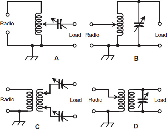
FIGURE 5-5 Simple transmatch (antenna tuner) circuits. At A, a tuner for low-impedance unbalanced loads; at B, a tuner for high-impedance unbalanced loads; at C, a tuner for low-impedance balanced loads; at D, a tuner for high-impedance balanced loads.
If you use a transmatch with your radio, you should make preliminary adjustments using an impedance bridge if you can get your hands on one. This little gadget eliminates the need for transmitting signals over the airwaves. If you can’t find an impedance bridge, you can adjust a manual transmatch according to the following procedure.
• Set your receiver and transmitter to the same frequency.
• Adjust the transmatch until the signals and/or noise “peak” in the receiver.
• Adjust the transmitter tuning and loading (if your transmitter has such controls) to the approximate settings for the frequency that you want to use.
• Switch the transmitter on, and apply a low-power signal to the transmatch.
• Adjust the transmatch for minimum SWR as indicated on a reflectometer placed between the transmitter and the transmatch.
• Retune the transmitter for normal operating output power. In latter-day radios, this process may involve nothing more than hitting a “tune” button for a couple of seconds.
• Identify your station.
• Record the positions of the transmatch controls for future reference.
Transmatches are especially handy for portable station operation. You can string up a random-wire antenna in any fashion and tune it to resonance by using a transmatch, unless it happens to be close to an exact multiple of 1/2 wavelength long. Generally, such antennas must measure at least 1/4 electrical wavelength if good results are to be obtained, although some transmatches can provide an impedance match with shorter wires. If you can’t get a match with a particular random wire, make it a little longer if you can (or shorter if you must), and then you should be able to match it.
Besides matching impedances, a well-designed and properly operated antenna tuner acts as a lowpass filter or bandpass filter, providing additional front-end selectivity for your receiver, improving the image rejection, and reducing the risk of front-end overload in case of a strong signal off-frequency. The transmatch also attenuates spurious outputs from your transmitter, including the harmonics.
Digital Interface Equipment
If you want to take advantage of the fascinating non-CW digital modes that exist today, you’ll need to equip your rig with a digital interface. At the very least, you’ll need a computer, although it doesn’t have to be a powerful one. An old computer, defunct for most other applications, will usually work fine for RTTY, PSK, MFSK, and other emerging digital modes. You should, in any case, have a good display so that you don’t get eyestrain from looking at all that decoded text!
In order to receive signals on any non-CW digital mode, you need to connect the audio output of your radio (from the headset jack, in most cases) to the “line in” jack on your computer. (If you use the microphone input jack on your computer, you’ll probably get too much audio, with consequent distortion.) Set the level on the sound card of your computer for a comfortable volume at the computer headset jack or speakers when your radio’s audio gain is set close to the middle of its range.
Once you’ve gotten the audio from your radio into your computer, you’ll need to download a program (or two, or three) that can decode the signals in the digital mode of interest. I use a program called DigiPan for PSK, another program called HamScope for PSK and MFSK, and a program called MMTTY for RTTY. All three of these programs are available online for free, and they all work on most versions of the Microsoft operating system (OS). Other programs exist, but most of them require payment. None of the ham radio digital programs take up much computer processing power or memory, so they run fast even on simple machines. Enter the name of the program of interest into your favorite search engine, and follow the links until you get a download that works.
In order to use a program once you’ve downloaded it, I recommend that you play around with it and see which button produces what action! (To heck with “help” menus!) I have a personal paradigm for learning freeware programs such as the ones mentioned above: COIES (“click on everything in sight”). You might expand this concept to COEISASWH (“click on everything in sight and see what happens”). If you conduct that exercise for a good long while, you’ll know how to use the program well enough so that you’re ready for the next step: Getting a digital interface unit. That’s a little box about the size of an old-fashioned outboard electronic keyer. Visit a ham radio convention or your local ham radio club and “pick some brains” for specific interface recommendations.
Utility-Operated Power Supplies
A fixed-station power supply provides your home station with the proper voltages and currents from the AC utility line. Nearly all active electronic devices require DC. Solid-state equipment commonly operates from 6 volts to 12 volts DC. Ham equipment using vacuum tubes needs 100 volts to 3000 volts DC. Here’s a breakdown of the components in a typical power supply of the sort used with fixed-station ham radio transceivers these days, along with a little “inside information” about how they work.
Power Transformers
We can categorize power transformers in two general ways: step-down or step-up. The output, or secondary, voltage of a step-down transformer is lower than the input, or primary, voltage. The reverse holds true for a step-up transformer, in which the output voltage exceeds the input voltage.
Most latter-day electronic devices need only a few volts to function. The power supplies for such equipment use step-down power transformers, with the primary windings connected to the utility AC outlets. The transformer’s physical size and mass depend on the amount of current that you expect it to deliver. Some devices need only a small current at a low voltage. The transformer in a radio receiver, for example, can be physically small. A large Amateur Radio transmitter or linear amplifier needs more current. The secondary windings of a transformer intended for that application must consist of heavy-gauge wire, and the cores must have enough bulk to contain the large amounts of magnetic flux that the coils generate.
Some circuits need high voltage. The cathode-ray tube (CRT) in an old-fashioned home television (TV) set needs several hundred volts, for example. Some Amateur Radio power amplifiers use vacuum tubes, even today, which need upwards of 1000 volts! The transformers in these linears are step-up types. They must have considerable bulk because of the number of turns in the secondary, and also because high voltages can spark, or arc, between wire turns if the windings aren’t spaced far enough apart.
Rectifier Diodes
Rectifier diodes are available in various sizes, intended for different purposes. Most rectifier diodes are made from silicon, so engineers call them silicon rectifiers. Some rectifier diodes are fabricated from selenium, so engineers call them selenium rectifiers. When you work with power-supply diodes, you must pay close attention to two specifications: the average forward current (Io) rating and the peak inverse voltage (PIV) rating.
If you drive too much current through a diode, the resulting heat will destroy it. When designing a power supply, you must use diodes with an Io rating of at least 1.5 times the expected average DC forward current. If this current is 4 amps, for example, the rectifier diodes should be rated at Io = 6 amps or more.
The PIV rating of a diode tells you the maximum instantaneous reverse-bias voltage that it can withstand. A well-designed power supply has diodes whose PIV ratings significantly exceed the peak AC input voltage. If the PIV rating is not great enough, the diode or diodes in a supply will conduct current for part of the reverse cycle, degrading the efficiency.
Half-Wave Circuit
The simplest rectifier circuit, the half-wave rectifier (Fig. 5-6A), has a single diode that “chops off” half of the AC cycle. This method of rectification has shortcomings. First, the output is difficult to filter; that is to say, you’ll find it hard to get rid of the pulsations (called ripple) in the DC that comes out of the diode. Second, the output voltage can drop considerably when the supply must deliver high current. Third, half-wave rectification puts a strain on the transformer and diodes because it works these components hard during half the AC cycle and lets them “loaf” during the other half.
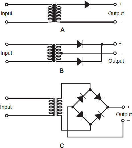
FIGURE 5-6 At A, a half-wave rectifier circuit; at B, a full-wave center-tap rectifier circuit; at C, a full-wave bridge rectifier circuit.
Full-Wave Center-Tap Circuit
You can take advantage of both halves of the AC cycle by means of full-wave rectification. A full-wave, center-tap rectifier has a transformer with a connection called a tap at the center of the secondary winding (Fig. 5-6B). The tap connects directly to electrical ground. This arrangement produces voltages and currents at the ends of the secondary winding that oppose each other in phase. These two AC waves are individually half-wave rectified.
Full-Wave Bridge Circuit
You can get full-wave rectification using a circuit known as a full-wave bridge rectifier. Figure 5-6C shows a schematic diagram of a typical full-wave bridge circuit. It does not require a center-tapped transformer secondary, so you can get away with a less expensive transformer. In addition, this method of rectification uses the entire secondary winding on both halves of the wave cycle, so it makes more efficient use of the transformer than the center-tap circuit does. The bridge circuit also places less strain on the individual diodes than a half-wave or full-wave center-tap circuit does.
Voltage-Doubler Circuit
You can connect diodes and capacitors together to deliver a DC output of approximately twice the positive or negative peak AC input voltage. Engineers call this arrangement a voltage-doubler power supply. It’s a compromise, though, if you want to get high DC voltage, because voltage drops considerably when you demand a lot of current from it. If the current fluctuates, so does the output voltage (the higher the current, the lower the voltage). Nevertheless, in low-current systems, this type of rectifier can work okay. Figure 5-7 is a simplified diagram of a voltage-doubler power supply. It takes advantage of the entire AC cycle, so it constitutes a full-wave voltage doubler. It serves as its own filter because the capacitors “smooth out” the pulsations in the DC that comes out of the diodes.
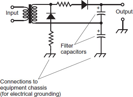
FIGURE 5-7 A full-wave, voltage-doubler power supply.
Filtering
Most DC-powered devices need something like the DC that would come from a battery, not the rough, pulsating DC that emerges from most simple rectifiers. You can eliminate, or at least minimize, the ripple in the rectifier output using a power-supply filter.
The simplest power-supply filter consists of one or more large-value capacitors, connected in parallel with the rectifier output, as shown in Fig. 5-8. An electrolytic capacitor makes a good component for this purpose. It’s polarized, meaning that you must connect it in the correct direction. A given electrolytic capacitor also has a certain maximum rated working voltage. Pay attention to these particulars!
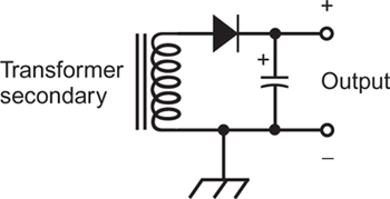
FIGURE 5-8 You can use a large-value capacitor all by itself as a power-supply filter.
You can obtain enhanced ripple suppression by placing a large-value inductor in series with the rectifier output along with a large-value capacitor in parallel. When an inductor serves in this role, engineers call it a filter choke. In a filter that uses a capacitor and an inductor, you can place the capacitor on the rectifier side of the choke to construct a capacitor-input filter (Fig. 5-9A). If you locate the filter choke on the rectifier side of the capacitor, then you have a choke-input filter (Fig. 5-9B).
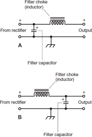
FIGURE 5-9 At A, a capacitor-input filter; at B, a choke-input filter.
Voltage Regulation
When you expect a power supply to deliver high current intermittently, you can employ a power transistor along with a Zener diode to obtain voltage regulation, using a circuit such as the one in Fig. 5-10. You can also find voltage regulators in integrated-circuit (IC) form. Such a regulator chip goes in the power-supply circuit at the output of the filter.
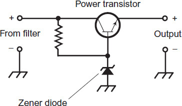
FIGURE 5-10 A voltage-regulator circuit using a Zener diode and a transistor.
“Tanglewire Gardens”
Most of us have computer workstations, usually with multiple peripherals and ancillary equipment, such as a printer, a scanner, a modem, a router, a cordless phone, a desk lamp or two, a charging bay (for devices such as tablet computers and cell phones), and so on. All of these things get their power, either directly or indirectly, from the 117-volt utility system. As a result, anyone with a substantial computer workstation will end up with a “tanglewire garden” behind and under the work desk. The same thing will happen eventually, if you gather enough gear in your ham shack.
“Tanglewire gardens” can look dangerous, as if they would present a high fire risk, but they needn’t pose a hazard. If you know how to connect and arrange the wires properly, it doesn’t matter from a safety standpoint how much you snarl them up, although you might want to affix labels on the cords near their end connectors (on each end) so that you don’t get them confused with each other when the inevitable malfunction occurs and you have to pull out and replace one of the components of your system.
Figure 5-11 shows the “tanglewire garden” underneath my ham radio station. In addition to the radio itself, this system includes a computer, two displays, a digital communications interface between the radio and the computer, a microcomputer-controlled reflectometer and RF wattmeter, an audio amplifier for the computer and radio, a wireless headset, a desk lamp, and an external hard drive that needs its own “power brick.” That’s 10 devices or cords in total, all deriving their power from a single outlet in the wall protected by a 15-amp breaker at the main utility box.
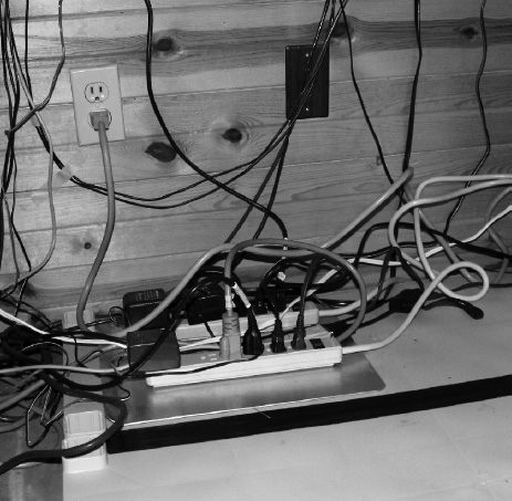
FIGURE 5-11 “Tanglewire garden” beneath the author’s electronics workbench. A heavy-duty UPS (out of the picture to the right) serves two power strips mounted on a metal baking sheet that rests on detached plastic shelves.
In order to ensure smooth operation of the system in case of a power failure, all of the devices go to the wall outlet through a commercially manufactured uninterruptible power supply (UPS). The UPS has a battery that charges from utility electricity under normal conditions, but provides a few minutes of emergency AC (with the help of some sophisticated electronic circuits) if the utility power fails. That few minutes gives me time to deploy my backup generator, described later in this chapter, without having to shut any of the devices down. The UPS has four outlets in the back, two of which go to power strips with six outlets each, and the other two of which remain empty. There are 12 available outlets in the power strips, 10 of which are in active use. The UPS also has a transient suppressor built-in. Figure 5-12 is a block diagram of the general arrangement.
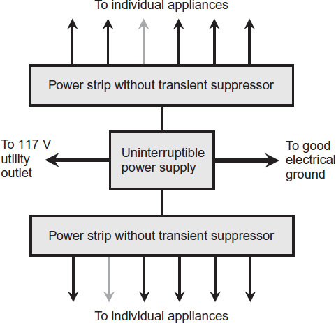
FIGURE 5-12 Block diagram of the “tanglewire garden” beneath the author’s workbench. The power strips include breakers but not transient suppressors; the UPS contains a transient suppressor that serves the whole system. Gray arrows represent unused outlets.
I’ve taken three extra precautions, aside from making sure that I don’t overload the wall outlet, to ensure that my “tanglewire garden” remains safe. You should do the same with your fixed station equipment!
1. First, if you look carefully at Fig. 5-11, you’ll notice that I’ve mounted the power strips on a metal sheet. It’s a solid aluminum baking sheet. I glued the strips down there with epoxy resin. This precaution keeps the power strips from setting anything (other than themselves) on fire if they start shorting out and sparking, a stunt that these things have been known to perform, occasionally with disastrous results.
2. Second, I don’t let any cord splices or other sensitive electrical points lie directly on the floor. The baking sheets, as well as all points in the cords where splices exist, are set up on thick plastic shelves. Although I’ve never been flooded out, my basement floor will get wet if a sudden cloudburst occurs. (Of course, in that event I won’t power up the ham shack at all until the floor dries out!)
3. Third, I’ve connected a dedicated ground wire from the chassis of the UPS to a known electrical ground. I tested the wall outlet underneath the workbench to ensure that the “third prong” actually goes to the electrical ground for the house.
Small Backup Generators
You can find compact, portable combustion generators for use in homes and small businesses. Some combustion generators are also suitable for use by campers. For people living in remote areas, a combustion generator might constitute the primary, if not the only, source of AC electricity for common appliances. And of course, every good fixed ham radio installation ought to have one!
How They Work
A small combustion generator provides 117 volts AC in the United States (234 volts in many other countries) at 60 Hz. Larger generators in the United States also supply 234 volts AC at 60 Hz for heavy appliances, such as electric ranges and laundry machines. The generator’s internal combustion engine can range in size from a few horsepower, comparable to the one in a lawn mower or snow blower, to hundreds of horsepower, comparable to the engines in trucks, tractors, and construction equipment.
In the simplest type of AC generator, a coil of wire, attached to the shaft of the combustion engine, rotates between a pair of powerful magnets. If you connect a load, such as your radio, to this coil, an AC voltage appears across that load as each point in the wire coil moves past the lines of flux produced by the magnets, first in one direction and then in the other direction, over and over. In an alternative arrangement, the magnetic poles revolve around the wire coil, which remains fixed.
The AC voltage that a generator can produce depends on the strength of the magnets, the number of turns in the wire coil, and the speed of rotation. The AC frequency in a simple generator depends only on the speed of rotation. In the United States, the speed is 3600 revolutions per minute (3600 r/min) or 60 revolutions per second (60 r/s), resulting in an output frequency of 60 cycles per second (60 Hz). In many other countries, the rotational speed is 3000 r/min, producing an AC frequency of 50 Hz. In order to maintain a constant rotational speed for the generator under conditions of variable engine speed, mechanical regulating devices are required.
When you connect a load to the output of a simple generator, the engine has a harder time turning the generator shaft, as compared with the situation when no load exists. As the amount of electrical power demanded from a generator increases, so does the mechanical power required to drive it, and therefore, the amount of fuel consumed per unit of time. The electrical power that comes out of a generator is always less than the mechanical power required to drive it. The lost energy shows up as heat in the generator components. To maintain the proper AC frequency, a simple generator’s engine must run at a constant speed under conditions of variable load. That state of affairs can prove difficult to attain, but latter-day engineers have found a way around the trouble!
Small Gasoline-Powered Generators
Advanced small-scale generators circumvent the need for constant motor speed by converting the generated AC to regulated DC, and then using a power inverter to generate AC from that DC. If the motor speed changes, the DC voltage stays the same because the regulator circuit holds it constant, so the output AC voltage stays constant too. In the best commercially manufactured generators, the inverter produces a near-perfect sine wave to ensure that the machine can properly operate sensitive electronic devices, such as computers, computer-controlled radios, printers, scanners, modems, and routers.
Figure 5-13 shows my portable gasoline generator with a power inverter that can provide around 1600 watts of clean sine-wave AC electricity when needed. This machine can run my ham station under full-power-transmit conditions, as well as all three of my computers and the microcomputer-controlled furnace, all at once. It has a tank that holds 1.1 gallons (4 liters) of high-octane, unleaded gasoline. With a load of a few hundred watts, that amount of fuel provides several hours of continuous, reliable AC electricity. This generator has proven itself worthy as a backup power source in winter storms when utility failures would otherwise have meant no heat for my house, as the furnace electronics and fan require 117 volts AC to function!
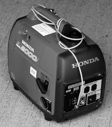
FIGURE 5-13 A portable, gasoline-fueled generator, capable of providing up to 1600 watts of clean sine-wave AC power at 117 volts. (The tied-up cord is the ground wire.)
My Arrangement
The Honda EU-2000i portable gasoline-fueled generator (Fig. 5-13) forms the heart of my emergency backup power ensemble. In addition to the generator, I use several extension cords and power strips to distribute electricity to the points where I need it the most during a utility outage. I always keep in mind the maximum power that the generator can provide; I never let it come close to “maxing out.” You can use this general configuration as a template for your own system if you want to install one, tailoring the specifics to meet your needs.
Figure 5-14 shows the two AC outlets on my generator. The cord on the left goes to the furnace fan and electronics. The cord on the right goes to my ham shack, several LED lights for the house, and all my computers by way of a power strip in the garage with an LED lamp to indicate when it’s getting generator power. (This strip does not have a transient suppressor because the UPS, which also goes to all the electronics that I want to provide with backup power, has a built-in transient suppressor.) When a power failure occurs, I unplug the UPS from the utility mains and plug it into the generator, physically removing the plug from the utility outlet before putting it into the generator outlet.
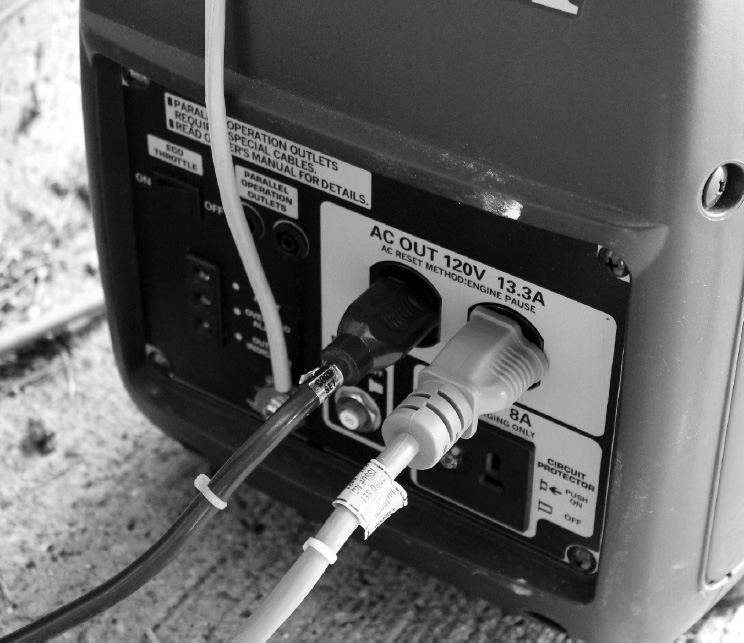
FIGURE 5-14 My portable generator has two AC outlets. The cord on the left goes to the furnace electronics and fan; the cord on the right goes to the ham shack.
Always try to balance the loads among multiple outlets in a generator that has more than one outlet. Ideally, each outlet should do roughly the same amount of work. This precaution ensures that the generator will operate at maximum efficiency. In some generators, the outputs appear in different phases. If I were to connect the entire load to, say, the left-hand outlet in the situation of Fig. 5-14, it would be like seating all the passengers on the left-hand side of an aircraft. The generator would function, but probably not at its best efficiency.
As a final precaution to keep the generator operating at its best, you should connect the generator’s ground terminal to a known electrical ground that you have tested for continuity with the main ground for your whole house. My arrangement comprises a single heavy length of wire and a clamp going to a cold water pipe. I’ve satisfied myself that the cold water pipe connects directly to the main electrical ground for the house by performing a continuity test.
Warning! Always locate a generator so that its exhaust can vent freely to the outside. The best way to make that happen is to keep the generator outdoors when running it. Never run your generator in a garage (even an open one) or a partially enclosed space of any kind. Buy a carbon-monoxide detector if you don’t already have one, and place it in your house near the rooms where you sleep. Keep its batteries fresh. That way, you’ll know if generator exhaust “blows” into the house, a situation that can arise with amazing ease, as I discovered when I ran it in the woodshed under my dining room. My carbon-monoxide detector sounded its alarm after only a few minutes of generator run time!
Warning! An on-site generator must run only when your house wiring is completely separated from the electric utility wiring with a double-pole, double-throw (DPDT) isolation switch installed and tested by a certified electrician. Alternatively, you can plug appliances into the generator through cords that have nothing whatsoever to do with your house wiring, as I do. If you don’t follow these rules strictly, backfeed can occur, in which electricity from the generator gets into the utility lines near the home or business where the generator operates. Backfeed can endanger utility workers and damage electrical system components. And in case you’ve wondered, switching off the main breaker at your utility box will not guarantee that no stray voltage can make its way onto the power lines outside your house. Avoid backfeed at all costs!
Noise, Noise, Noise!
In wireless communications practice, RF noise that comes from outside is called external noise. The more sensitive the receiving equipment, and the longer the distance over which it has to work, the more significant this type of noise becomes.
Cosmic Noise
Electromagnetic radiation from outer space, called cosmic noise, occurs throughout the entire EM spectrum, from the VLF radio band where waves measure tens of kilometers long to the realm of X rays and gamma rays where scientists measure wavelengths in nanometers (millionths of a millimeter) and picometers (thousandths of a nanometer). At the low radio frequencies, the ionized upper atmosphere of our planet prevents the noise from reaching the surface. At some higher radio frequencies, the lower atmosphere prevents the noise from reaching us. But at many frequencies, cosmic noise arrives at the surface at full strength.
Cosmic noise can be identified by the fact that it correlates with the plane of the Milky Way, our galaxy. The strongest galactic noise comes from the direction of the constellation Sagittarius (“The Archer”) because this part of the sky lies on a line between our Solar System and the center of the galaxy. Galactic noise was first noticed and identified by Karl Jansky, a physicist working for the Bell Laboratories in the 1930s. Jansky conducted experiments to investigate and quantify the earth’s atmospheric noise at a wavelength quite close to that of the ham radio 21-MHz band. He found some radio noise that he couldn’t account for, and then he noticed that its orientation correlated with the location of the Milky Way in the sky. Jansky’s antenna was a simple affair like the ones used by hams.
Along with noise from the sun, the planet Jupiter, and a few other celestial objects, galactic noise accounts for most of the cosmic noise arriving at the surface of the earth. Other galaxies radiate noise, but because those external galaxies lie much farther away from us than the center of our own galaxy does, sophisticated equipment is needed to detect the noise from them.
Solar Noise
The amount of radio noise emitted by the sun is called the solar radio-noise flux, or simply the solar flux. The solar flux varies with frequency. But no matter what the frequency (or wavelength), the level of solar flux increases just after a solar flare occurs. A sudden increase in the solar flux indicates that shortwave broadcasting and communications conditions (including ham radio) might deteriorate within a few hours.
The solar flux is commonly monitored at a wavelength of 10.7 centimeters, which corresponds to a frequency of 2800 MHz. At this frequency, which is about 100 times the frequency of the ham radio 10-meter band, the earth’s atmosphere has little or no effect on radio waves, so the energy reaches the surface at full strength.
Atmospheric Noise
Electromagnetic noise is generated in the atmosphere of our planet, mostly by lightning discharges in thundershowers. This noise is called sferics. In a radio receiver, sferics cause a faint background hiss or roar, punctuated by bursts of sound we call “static.” Figure 5-15 shows an example of this noise as it would look on the display of a laboratory oscilloscope connected into a radio receiver.
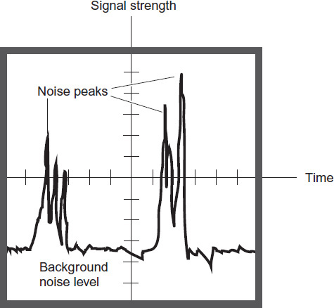
FIGURE 5-15 If you connect an oscilloscope into a radio receiver and listen to sferics, you’ll see a display that looks something like this drawing.
A gigantic voltage constantly exists between the surface of the earth and the ionosphere. The earth and ionosphere behave like concentric, spherical surfaces of a massive capacitor, with the troposphere and stratosphere serving as the insulating material (called a dielectric) that keeps the charges separated. Sometimes this dielectric develops “holes,” or pockets of imperfection, where discharge takes place. Such “holes” are usually associated with thundershowers. Sand storms, dust storms, and volcanic eruptions also produce some lightning, contributing to the overall sferics level.
Sferics are not confined to our planet! A great deal of radio noise is generated by storms in the atmosphere of the planet Jupiter. Astronomers can “hear” this noise with radio telescopes. Sferics probably also occur on Saturn, and perhaps on Uranus, Neptune, Venus, and Mars as well. In the cases of Venus and Mars, dust storms and volcanic eruptions would likely be the cause of sferics.
Precipitation Noise
Precipitation noise, also called precipitation static, is radio interference caused by electrically charged water droplets or ice crystals as they strike metallic objects, especially antennas. The resulting discharge produces wideband noise that sounds similar to the noise generated by electric motors, fluorescent lights, or other appliances.
Precipitation static is often observed in aircraft flying through clouds containing rain, snow, or sleet. But occasionally, precipitation static occurs in radio communications installations. This phenomenon is especially likely to happen during snow showers or storms; then the noise is called snow static. Precipitation static can make radio reception difficult, especially at low frequencies (long wavelengths).
In a good radio receiver, a noise blanker or noise limiter can reduce the interference caused by precipitation static. A means of facilitating electrical discharge from an antenna, such as a large-value, heavy-duty inductor between the antenna and ground, can also help. If the antenna elements have sharp points on the ends, you can blunt them by installing small metal spheres on those ends. If you do that, you’ll have to shorten the elements slightly to make up for the loading effects that the spheres introduce.
Coronae
When the voltage on an electrical conductor (such as an antenna or high-voltage transmission line) exceeds a certain level, the air around the conductor begins to ionize. The atoms in the air gain or lose electrons, so that they become electrically charged. If the effect becomes significant, it can cause a blue or purple glow called a corona that can be seen at night. This glow commonly occurs at the ends of a radio-broadcast or communications-transmitting antenna element when the transmitter has high power output. Coronae occur increasingly often as the relative humidity rises because it takes less voltage to ionize moist air than it takes to ionize dry air. Coronae produce a strong hiss or roar in radio receivers.
Coronae can occur inside a coaxial cable that feeds an antenna just before the dielectric material breaks down, ruining the cable for good. Poorly designed antennas with high-power transmitters can subject a transmission line to that sort of stress. So can nearby thundershowers. A corona is sometimes observed between the plates of capacitors handling large voltages. Also it is more likely to occur at the end of a pointed object, such as the end of a whip antenna, than on a flat or blunt surface. Some antennas have small metal spheres at the ends to minimize the occurance of coronae.
Impulse Noise
Any sudden, high-amplitude voltage pulse will generate an RF field, and radio receivers will often pick it up. It’s called impulse noise, and it can come from all kinds of household appliances, such as vacuum cleaners, hair dryers, electric blankets, thermostats, and fluorescent-light starters. Impulse noise tends to get worse as the frequency goes down, and can plague AM broadcast receivers to the consternation of their users. Serious interference can occur in shortwave receivers, but it gets less severe as the frequency rises, and it rarely poses a problem above 30 MHz.
You can minimize impulse noise problems by ensuring that you have a good ground system. All the components in the system should be grounded by individual wires to a single point. A noise blanker or noise limiter can also help, if the receiver has one. A shortwave or ham radio receiver should be set for the narrowest response bandwidth consistent with the mode of reception.
Ignition Noise
Ignition noise is impulse noise generated by the electric arcs in the spark plugs of an internal combustion engine. Many different kinds of devices produce it, including automobiles and trucks, lawn mowers, and gasoline-engine-driven generators. Figure 5-16 shows how ignition noise would look on an oscilloscope connected into the sensitive amplifiers of a radio receiver.
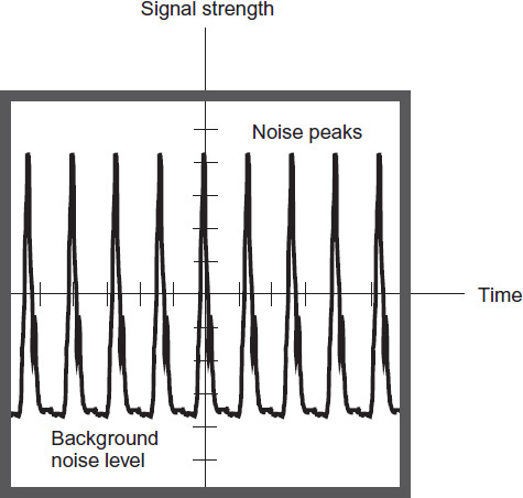
FIGURE 5-16 Here’s what ignition or impulse noise looks like on an oscilloscope display connected into a radio receiver.
In a shortwave or ham radio receiver, a noise blanker can often work wonders to get rid of ignition noise problems. (In stubborn cases, the noise blanker can’t deal with the energy pulses, and you have to rely on a limiter instead.) The pulses of ignition noise are of very short duration, although their peak intensity can be considerable. Noise blankers are designed to literally switch the receiver off during these brief spikes.
Power-Line Noise
Utility lines, in addition to carrying the 60-Hz AC that they’re meant to transmit, carry other currents. These currents have a broadband nature. They result in an effect called power-line noise. The “rogue currents” usually occur because of electric arcing at some point in the utility grid. The arcing might originate in household appliances; it can take place in faulty or obstructed utility transformers; it can occur in high-tension lines as a corona discharge into humid air. The currents cause the power line to radiate EM fields like huge radio transmitting antennas!
Power-line noise sounds like a buzz, hiss, or roar when picked up by a radio receiver. Some types of power-line noise can be attenuated by means of a noise blanker. Other types of electric noise defy noise blankers, and the best you can do is hope that a limiter will give some relief by giving the desired signals a “fighting chance” against the noise.
The Worst Noise of All: EMP
An electromagnetic pulse (EMP) is a sudden burst of EM energy caused by a single, abrupt change in the speed or position of a group of charged particles. An EMP has no well-defined frequency or wavelength; it exists over the entire EM spectrum including radio wavelengths, infrared, visible light, ultraviolet, X rays, and gamma rays. An EMP can be generated by arcing, and on a radio receiver, multiple small EMPs sound like popping or static bursts.
An EMP can contain a fantastic amount of power for a short time. Lightning discharges have been known to induce current and voltage spikes in nearby electrical conductors, of such magnitude that equipment is destroyed and fires are started. If a solar disruption suddenly sends a huge quantity of charged subatomic particles in the earth’s direction, an EMP can occur when the “tsunami” of particles encounters the earth’s magnetic field, which accelerates the charge carriers toward the geomagnetic poles.
The detonation of an atomic bomb creates a strong EMP. The explosion of a multimegaton hydrogen bomb at a very high altitude, while not creating a devastating shock wave or heat blast at the surface of the earth, could generate a disruptive EMP over an entire nation or a large part of a nation. The resulting voltages and currents in radio antennas, telephone wires, and power transmission lines could damage or destroy sensitive electronic components connected to them.