
Scanning the Image
11.1 A Little of the History of Television
Television was developed in the mid-1930s and two very different systems came to the fore: one was based entirely on an electronic platform using cathode ray tube technology that had been developed by the Marconi company; the other was an amalgam of electronics and mechanical shuttering to divide up the picture, developed in England by John Logie Baird, who was almost certainly the first man to transmit a moving picture over the airwaves.
Extraordinarily the Marconi system utilized interlace scanning and Baird’s method used, in effect, progressive scanning. It has taken 70 years for the world to realize that, in this respect, Baird was ahead of his time. Not only in that respect, for he arguably invented color television and 3D television and demonstrated both to the public; all this is well known and well documented, but sadly forgotten by many. There were many other differences. The Marconi company thought the ideal format would be landscape (that is, a rectangle that is wider than its height) and they scanned it horizontally, and Baird initially thought much of television would be illustrated radio so initially his first format was portrait (a rectangle that is higher than it is wide), this being more suited to talking heads, so he started by scanning his frame vertically, with a little curvature to the lines it has to be said. Later, when he moved to a 240-line format he also incorporated a 5 × 4 landscape aspect ratio.
Initially the basic principle of Baird’s camera was a lens focusing an image on a spinning disk, which had a series of holes in it (arranged as in Figure 11.1), behind which was a single photoelectric cell. In this illustration I have much exaggerated one of the problems with this system: the scans are circular in nature, resulting in an image made up of lines of information, shown in Figure 11.2. A very much bigger shutter with the holes all grouped near to the outer edge more or less solved this problem. Baird moved to larger shutters and finer holes grouped closer together, thus improving picture definition, but he did not have the resources of the Marconi company and this, together with other problems, resulted in the Marconi system being adopted for the first public broadcasting system by the BBC (British Broadcasting Company, later Corporation) in London.
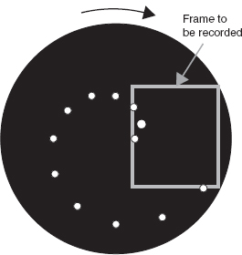

Figure 11.2: Baird’s scan (curvature much exaggerated)
Nevertheless Baird’s model did scan in the way we now describe as progressive, for the lines were scanned one after the other in a sequential way. The Marconi system scanned all the odd numbered lines of a single picture first and then went back and scanned all the even numbered lines, just as standard definition television does today. The considerable advantage of this scanning format is that it results in a small amount of data being scanned continuously and fools the eye/brain combination of the viewer into thinking it is seeing twice as many pictures, thus considerably reducing flicker, which is especially apparent in the highlights of a picture. As human vision is blessed, or cursed, with a phenomenon known as the persistence of vision the audience, more or less, happily adds together both scans and believes it is seeing all the image at the same time.
Persistence of vision means that any image we see at a given moment takes some time to die or fade away; it persists in the retina of the eye and within the brain. The image will still contain the remnants of an earlier moment and we add together a little bit of past images to the immediate and current image. If the human eye/brain combination did not have this anomaly then cinema images would not work and television images would be quite unacceptable in their current form.
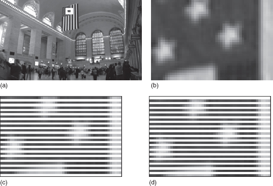
Figure 11.3: Pixels in the lace and interlace scans: (a) scan of original scene; (b) blow up of selected section showing both lace and interlace scans added together; (c) lace scan; (d) interlace scan
11.2 Interlace Scanning
As we have seen, interlace scanning is simply the dividing up of an image into horizontal lines and sampling the data along the odd numbered lines, then returning to the top of the picture to begin scanning the lines that were previously ignored – the even numbered lines – in the same way.
The definition, or perceived sharpness, of the resultant image will effectively be determined by two factors – how many lines the picture is divided up into vertically and how often a sample is taken as each line is scanned. The two most popular High Definition (HD) standards in use at present either scan 1080 lines and sample each line 1920 times or scan 720 lines and sample each line 1280 times.
Figure 11.3 shows how the scanning takes place. We can see that when both the lace and the interlace scans are performed, small blocks of information are produced. Each block is an even density; each block is representing the output of one pixel on the camera’s chip. You will also see that if the small area on the flag is blown up then the blocks, or pixels, make little sense even when both scans are shown together, for it requires a large number of lines and very frequent sampling to make our eyes believe we are seeing a completely smooth tonal range with sufficient sharpness for us to believe we are looking at real life. Figure 11.3 has been prepared so that the original picture of Grand Central Station and all the derivative pictures actually come from a master photograph scanned at a resolution giving 1080 vertical lines each sampled 1920 times.
Think about this: the master picture looks to be of very high quality but the blow-up of the section of the flag proves it is not. This is how digital imaging works. With enough pixels we can produce an image that the human eye thinks is perfect; hence the need for HD images – the pictures are so much more realistic.
11.3 Progressive Scanning
With the introduction of the 1920 × 1080 HD pixel array it became possible to fill a cinema screen with a digital image arguably as good as a film image, as we have seen in Chapter 10. Unfortunately if the HD image was captured in interlace scanning the way things moved across the screen was not acceptable to a cinema audience. This is probably for two main reasons: first, when blown up to the huge size of a cinema screen the interlaced image was not completely convincing as real life and, perhaps more importantly, did not display the kind of movement on the screen the audience had come to expect in the cinema – this we call conditioning. Personally I am not convinced we look at the best pictures possible in a cinema but they are the pictures we have become used to.
There are two issues when viewing pictures in the cinema: the screen is very dim compared with a television picture so flicker at 24 frames per second (fps), shown twice (i.e. 48 times a second), is not too big a problem and the display size is large, particularly when you consider the viewing angle from the audience’s eye. As an example it is common to view a standard definition picture in the home from a distance of around 6–10 times the height of the picture. As HD screens, which are usually bigger, come into the home the viewing distance is reduced to 3–5 times the height of the picture but, in a decent cinema, the viewing distance becomes 0.7–2.5 times the picture height.
So what did a cinema audience expect and how was it created? To answer this question we need to investigate two matters, image flicker and motion blur.
11.4 Traditional Cinema Flicker
Much as purists would like to deny it, all film images flicker to some degree. The current standard for the mechanical projection of 35 mm film is 24 fps, with each frame shown twice. This gives rise to a certain amount of flicker on the cinema screen, particularly noticeable in the brighter parts of the image. The audience are, happily, conditioned to this as just enough images are shown per second to be acceptable but even to begin to remove this flicker the display rate (fps) would have to be doubled. As we have seen, it is also true that the relatively dimmer picture in the cinema, compared to television in the home, makes flicker far less apparent. Things are just a little less simple than that; they are also a little more elegant. Figure 11.4 shows how a camera shutter is orientated to leave the aperture open during 180 degrees of its rotation and blank the aperture for the other 180 degrees. This is very simple and effective, for at 24 fps it results in an exposure of 1/48th of a second. When the shutter is closed the film is being moved to the next frame and when the shutter is open the time is given over to exposing the film to the image.
In the camera, which is usually close to the microphone picking up the sound, the film transport mechanism has to be very quiet. A claw mechanism is usually deployed, which might not be terribly fast at pulling down the film but is accurate and quiet. It does not necessarily have to be very kind to the film’s perforations as they will only pass through the camera once.
In the cinema projector things are a little different. In designing the projector a prime consideration is to maximize the amount of light reaching the screen. As the projector will almost certainly be in a room separate from the audience, known as the projection box, how much noise it makes is not a consideration. What is a consideration, though, is how kind the transport mechanism is to the film and its perforations, for whereas the camera only passes the film once, a film print may pass through a projector many hundreds of times.
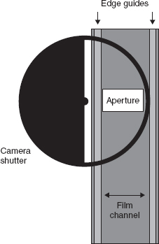
Figure 11.4: 35 mm film gate and camera shutter
Most cinema projectors use a transport mechanism driven by a device known as a Maltese Cross. The mechanism consists of sprocket wheel attached to a drive shaped a little like a Maltese Cross, which is driven by a rotating pin. This arrangement causes the sprocket to rotate intermittently, usually a quarter turn each time the pin hits one of the four slots in the cross. The advantages of this transport mechanism are that it is very kind to the film, as at least four perforations on each side of the film are engaged with the sprocket teeth at any one time, thus greatly reducing the load on each perforation, and it can therefore safely pull the film down much more rapidly, usually in one-quarter of the full frame rate, without damaging any of the perforations. It is, however, very noisy.
As the projector mechanism only needs one-quarter of total time to transport the film, the shutter can now be opened for 270 degrees and closed for 90 degrees. This increases the screen brightness by 50 percent relative to a 180-degree shutter. The disadvantage of this arrangement is that having a greater opening time than closed time brings us back to our old problem, flicker. Extending the shutter opening time will considerably increase the apparent flicker.
This is overcome by introducing a very small extra shutter blade, as shown in Figure 11.5, which effectively fools the eye into thinking it is seeing 48 fps despite every two consecutive frames being identical, as the same frame is still in the projector gate. This extra blade is known as the “phantom shutter”.
All this may seem less than relevant to HD cinematography; it is not, for it is important to understand what many film makers are asking the HD 24P format to try to replicate – the look and appearance of film when shown in a cinema or on television, warts and all! While I have happily shot several HD productions giving this look, I feel we might be missing something important. HD can have its own look; it may not be familiar to the lay audience but I, for one, like it very much and look forward to the day when, hopefully, I am asked to give my all to a pure HD image. That, perhaps, was the sponsor’s message!
11.5 How are Images Captured by the Two Scanning Formats?
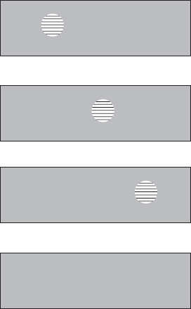
Let us use a simple example of a disk moving left to right across the frame to be photographed as in Figure 11.6(a). If we photograph this moving disk using interlaced scanning, then we will record a picture, known as a field, and each field will be photographed in a slightly different moment in time. Each field contains half the vertical information twice for every complete picture, the complete picture being known as a frame. As two fields are required to complete each frame, in US television 60 fields are required to complete the required 30 frames in every second of recording and in the UK 50 fields are required to complete 25 frames every second of recording.
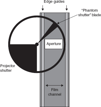
Figure 11.5: 3 mm film gate and projector shutter
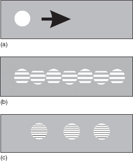
Figure 11.6: Sequential photography of movement: (a) original object; (b) photographed with interlace scanning; (c) photographed with progressive scanning
Each field is displayed sequentially on the screen so the progression of the disk across the picture will be displayed as in Figure 11.6(b).
With progressive scan each frame is captured in its entirety in a single moment in time and will be recorded as in Figure 11.6(c). If it were then to be written out to film there would be one complete disk recorded on each frame of film and this would very closely emulate an image recorded by a film camera. Unfortunately not all HD formats work this way.
Sony call the frame recording standard for HDCAM progressive segmented field (PSF). This means that although in our illustration the disk moving across the screen will be captured in its entirety at the given frame rate, it will currently be displayed electronically on a cathode ray tube (CRT) television in the same way as an interlace picture but with each lace and interlace field being from the same moment in time. This is not all bad, for it is exactly the way film is displayed when shown on television. On a CRT television screen, however, it will not appear as smooth a movement as an image captured using an interlace scan, where twice as many half-resolution fields are usually displayed per second, but it will be a much more acceptable image when shown in a cinema. That acceptability comes partly from the technical reasons described and partly from the fact that the audience is conditioned to expect a different kind of picture when watching television at home and a film in the cinema. Interestingly these differences may start to become less apparent as home screens for High Definition Television (HDTV) become larger and larger.
Another factor is coming into play in the domestic marketplace for televisions. There is a dramatic move from the purchase of CRT televisions to larger flat-screen televisions. Indeed, after 2006 one major British retailer stopped selling CRT televisions altogether. These larger televisions cannot be made using CRTs and the new flat-screen technology requires that the display is configured in the progressive scan format, thus solving many of the problems.
To take this a step further let us consider how interlace fields actually arrive at our television screen. In Figure 11.7 each box contains the image of one field containing half the vertical information of the moving disk but, importantly, each field has been captured in a different moment in time. When the audience looks at their television their persistence of vision adds the subsequent fields together and they believe they are seeing smooth movement. Up until recently this is how television has traditionally worked, both in the standard and HD arenas.
There is another, and possibly more important, human factor at work here – saccadic eyetracking. In essence this describes the fact that our eyes inherently follow a moving object; we inherited this from our ancient ancestors, where the ability to follow food or a predator was crucially important.
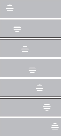
Figure 11.7: Interlace fields as displayed on a cathode ray tube
Figure 11.8, on the other hand, shows how a series of pictures shot in progressive scan television, and film, appear when shown on an interlace display device. Half the vertical information is shown on each field but between the first and the second fields the disk has not moved. While the viewers’ persistence of vision happily adds the fields together and sees the true resolution, they still only think they are seeing half the number of samples as the disk crosses the screen. This produces a juddering movement but, because saccadic eye motion is interrupted, the eye suddenly can’t follow the track accurately so splits the two fields into two separate objects moving across the screen. If the spacing of the objects on the two separate fields is small it appears as judder, but if it is large the eye starts to think of it as two separate objects. Fortunately, once the audience is conditioned to it this is hardly apparent to them, provided the distance between objects on the two fields is small.
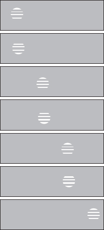
Figure 11.8: Pictures photographed with progressive scanning displayed on a cathode ray tube using interlace scanning
Many years of experience have enabled cinematographers trained in film to minimize the perceived effect. Remember we have been looking at film on television displayed just this way for many years and many of the audience have been perfectly happy with the results. Some technicians are less than happy, which is one reason why so much work is being done on the new HD standards in the hope that in the near future a much higher technical, artistic and emotionally involving picture presentation format will result.
Why are we just as happy with the two very different ways of delivering the whole of the information? The two effects work best with different genres. Here are two examples. A feature film, being fiction, usually though not always contains slowly moving objects and the film exposure and progressively scanned HD are best suited to the recording of slowmoving objects. Interlace scanning is much more suited to fast-moving objects. Witness the fact that most sports fans hate seeing their favorite game shot on film – they much prefer it on television, in interlace.
Our eyes can be fooled in several different ways into believing that sequentially displayed still pictures are a true representation of a moving object, thank goodness, or cinema and television would be in dire trouble!
Each interlace field is photographed in half the time taken for a complete frame and each of those fields will therefore have been photographed in half the time a complete progressive scan will have taken place. Therefore the effective shutter speed for a field of interlace will be half the shutter speed for a complete frame. The shorter the exposure time that is used to capture a picture of a moving object, the sharper will be the leading and trailing edge of that object on the picture. Think of trying to photograph a car passing the camera using a relatively slow shutter speed: the background will be sharp since the camera did not move relative to it, but there will be a noticeable blur surrounding the car as that is moving relative to the camera.
The core difference is that although the interlace fields are sharper we are given twice as many of them per second so our brain, seeing so many, assimilates them as a true rendition of a moving image. With progressive scan, and film, we are tricked into believing we are seeing a true moving image, because although we are seeing half as many pictures they have twice the resolution but, more importantly, they have a blurred edge, because the exposure is twice as long, and blurred, just as persistence of vision gives us in real life. Which is all fine, so long as the movement in the frame is relatively slow. To an experienced eye rapid movement within the frame shot on film at 24 fps is not satisfactory at all – the judder can be most disturbing. If a good Director of Photography (DP) is asked to photograph rapid movement like this they will nearly always try to work with a small depth of field, thus putting the background out of focus and removing the relative movement between the moving object and its surroundings – that horrible judder is now no longer apparent. It is interesting that this is one of the primary reasons good DPs and camera operators hate unmotivated pans.
The conclusion must be that either you need to give the eye a sufficient number of sharp pictures that they appear to blur together in our brain or you need to record some kind of blur on each frame so that the brain is satisfied it is looking at real life. In order to give a little light relief to the simple moving disk, Figure 11.9 shows first a hot air balloon stationary in the sky and then a representation of a single frame of progressive scan or film as captured when the balloon starts to move. Looked at in isolation this blurred frame looks odd, but when 20 or more pictures of its subsequent movement are shown every second the viewer will be completely convinced they are watching natural movement.
11.6 Printing Out to Film
As yet cinemas that can project a digital image via an HD electronic projector are in the minority and therefore in most cases it is necessary to take our digital image and transcribe it to a film print for display in a cinema.

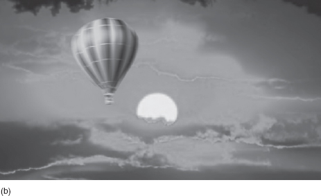
Figure 11.9: The effect of motion blur: (a) scene with no movement; (b) background still – balloon moving showing motion blur
First let us consider how a picture captured using interlace scanning will look on that piece of film. Remember the two fields have been captured at slightly different moments in time. Figure 11.10 shows how subsequent frames of our moving disk will look if the two fields making up a complete frame are both printed to a single frame of film – odd, to say the least. Fortunately this transfer technique, though used extensively in the past, particularly with CRT display devices in the transfer equipment, is not common now, though can still be found in some post-production houses – beware of them!

It is now possible to combine the two fields, superimposing them in the same space on the film print, and this is currently much more common; this will provide a single complete disk on each frame having full resolution, but that disk will be made up of alternate lines taken at different moments in time – believe me, this looks equally odd, at least to me, and though different, perhaps not quite so bad. It is possible to pass the image through a good adaptive interpolator that will improve things enormously and, thank goodness, this is much the most common procedure today.
Were we to print a complete frame of picture acquired using progressive scan we would get a series of complete disks, where all the information contained in each frame had been acquired at the same moment in time, very much as in Figure 11.11, and also very much as if it had been recorded on film.
At present, progressive scanned images when used in the television environment may not have quite as many advantages as some people would have us believe. There are many subjects, notably sport, where interlace scanned pictures are more acceptable if shown on a television at the present time; they are also what the audience is used to. However, ABC in America and some Scandinavian countries show sport in a 720P with 60 fps or 720P with 50 fps, both of which give a wonderfully smooth motion; indeed, this has been the ATSC specification since 1990. The difference here is that although the pictures are captured in progressive scan the frame rate is much higher, 50 or 60 full frames per second, and it is this that removes most of the problem.
I strongly favor this move as it undoubtedly makes movement appear much more natural no matter what the subject, be it fiction, documentary or sport.
Having said all the above, if you wish to acquire your images digitally and then want to show them in a cinema, via either a digital projector or from a film print, my belief is that capturing them with progressive scan is essential to give the audience the experience they expect of cinema presentation.
There are a number of other issues that affect the perceived quality of a digitally acquired picture and most of these are discussed in the next chapter, covering line standards.