
Monitors and Cabling
If, like me, you choose to light to your monitor then this chapter might just be one of the most important you ever read. Setting up monitors is not difficult or particularly time-consuming but for someone from a film background it can, at first, be a little daunting.
21.1 What Kinds of Monitor are Available?
21.1.1 Cathode Ray Tube (CRT) Monitors
Monitors using CRT technology have been the most common to be offered by high-end suppliers, though this is beginning to change as high-quality flat-screen monitors are now available. They nearly all come with a 16 × 9 screen, for which the most likely dimension of the diagonal of the picture will be 9, 14 or 24 inches. The early High Definition (HD) CRT monitors were interlace scan only and the picture therefore stuttered slightly when the camera was panned rapidly if that camera were set up to shoot in Progressive scan. This effect is never recorded, it being partly a function of having to display a progressively scanned picture on an interlace scan monitor and partly a function of the high modular transfer function (MTF) of HD in the middle tones of the image. More recently, true Progressive scan monitors have come into use and with these the stuttering picture never appears. Not surprisingly the Progressive scan monitors are more expensive.
21.1.2 Liquid Crystal Display (LCD) Monitors
Early HD LCD monitors had, most commonly, a screen diagonal measuring 6 or 7 inches. These sizes are now more often used as on-board screens either as the viewfinder if the camera operator prefers this or as a viewing guide for the focus puller. These screens are far too small for the focus puller to judge focus by, but do at least confirm what is actually being photographed. Recently, LCD screens have become available in much larger sizes, with a 14-inch becoming very popular as a Director’s monitor. LCD monitors rarely exhibit the stutter shown on CRT monitors as the difference in their technology masks this effect, or at least masks a great deal of this effect. They are usually light weight and quite pleasant to look at, though I would hesitate to judge lighting or sharpness on a smaller one.
Plasma screen technology allows for large screens, often with a screen diagonal sometimes measuring between 42 and 61 inches; even larger screens are now coming onto the market. They can be very attractive to look at provided you are not too close. They are very slim but do not quite have the quality of picture of a large CRT screen. They are also expensive but do mask the stutter effect perhaps even better than an LCD monitor.
21.2 Lining up Your Monitor
One must take great care in lining up your monitor especially if you are going to judge your lighting via your monitor; fortunately this can be carried out both quickly and accurately.
Most cameras will generate either European Broadcasting Union (EBU) color bars (Color Plate 10) or Society of Motion Picture and Television Engineers (SMPTE) color bars (Color Plate 11); many will generate both, with the selection between them somewhere in the camera’s menu. The object of the exercise, with either kind of color bars, is to get the bars correctly displayed by adjusting the brightness, chroma and contrast controls. EBU bars really require some sort of meter capable of reading the screen brightness, though in an emergency they can be lined up reasonably by eye. SMPTE bars, on the other hand, can reliably be lined up without a meter for they were designed so that an “eyeball” line-up would be reasonably, if not very, accurate. It is still possible to increase the reliability of your line-ups if you can measure screen brightness accurately in some way, even when using SMPTE bars.
Being British I used to favor EBU bars but since working more extensively with HD, where SMPTE bars are more often used, I have changed my mind and now feel much more comfortable lining up to SMPTE bars.
21.2.1 An SMPTE Line-up
The first parameters to set are brightness and contrast. Find the red bar and looking slightly below it find the three narrow vertical gray bars. Now switch the monitor to blue only. If at first you can’t find them then increase the brightness until they appear. Your monitor should now look very much like Figure 21.1. You now need to reduce the brightness until the left and the middle bars just disappear, leaving only the right hand of the three little bars still just visible. These three small bars on your monitor should now look very like Figure 21.2.
Towards the lower left-hand segment of the screen you will find a white square. Using the contrast control adjust this square until it just bleeds into the adjoining areas; now back off the contrast control until this effect just disappears. This is often described as reducing it until it ceases to “glow”. Or you can use some exposure meters to set contrast (see below).
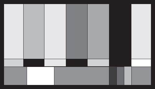
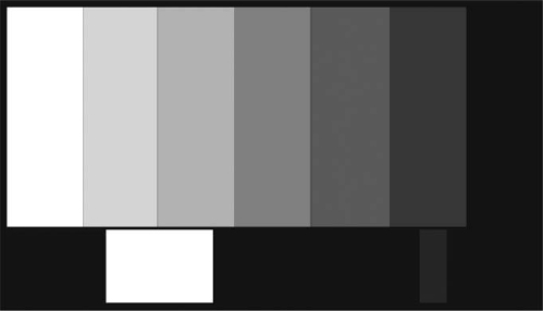
Figure 21.2: SMPTE Color Bars with “Blue Only” switched ON – correctly set up
With any television format the brightness and contrast controls are never wholly independent of each other, so you may well have to go through the loop of making adjustments to both controls until you find you are no longer making any more changes.
The third parameter to set is chroma. On the screen you should see four vertical white bars with three much darker bars between them. If chroma is incorrectly set this part of the screen may look something like Figure 21.1. Below each bar you may be looking at a much smaller and rectangular section to the bar. For the moment ignore all the other portions of the screen.
What you have to try to achieve is a situation where all seven long bars match, as near as possible, the smaller rectangular sections below them. The control we are going to adjust is chroma. Adjust the control until you have the best possible match between the large vertical bars and the smaller sections below them on all seven bars. When you have successfully done this the screen should look something like Figure 21.2; in other words the smaller rectangular sections have effectively disappeared.
When you are satisfied with your result switch off the “Blue Only” control – your line-up is now complete.
21.2.2 Lining up Using EBU Bars
First set the monitor to underscan, which sets the picture slightly smaller than the screen. Using the brightness control adjust the right-hand black bar to match the density of the surrounding unused screen area. Now switch the monitor to “Blue Only”. Using the chroma control adjust the second bar from the left again until the density of the bar exactly matches the surrounding screen density. Using the contrast control adjust the extreme left-hand bar, which is white, brighter and brighter until it just appears to “glow”, then back off just a little until it stops glowing. You can set the contrast with some exposure meters (see below). Switch off the “Blue Only” control. Switch the camera back to picture and your monitor should be perfectly lined up.
Monitors should be lined up a few minutes after being switched on and every time the lighting environment surrounding the monitor changes.
21.2.3 Using an Exposure Meter
If you have an exposure meter that can cope with a flickering image, such as a Cine Meter II or a Spectra Combi II, place it with its flat disk attached over the extreme left-hand white bar on EBU bars or the white box bottom - left on SMPTE bars and adjust the contrast till the meter reads 27 foot candles. The same trick works with a Seconic L508 Cine with the dome retracted but the correct reading with this meter is 54 foot candles. The difference in reading is caused by the way meters behave when faced with a scanned picture. To find out if your meter should read 27 or 54 foot candles simply do a careful eyeball line-up and place your meter on the appropriate part of the screen; it will now read very close to either 27 or 54 foot candles. From now on set your screen contrast to the appropriate value nearest to your test reading. Some meters will not give an accurate reading from a screen; these are easily discovered as the reading will be unstable and jump around – these meters should not be used for lining up a monitor.
How you cable your monitor may not seem important; in fact, it is vital to your success.
There are three commonly found ways of outputting an HD color picture from a camera to either a stand-alone video recorder or a television monitor. They are called RGB (Red, Green and Blue), HDSDI (High Definition Serial Digital Interface) and SDSDI (Standard Definition Serial Digital Interface). As the name suggests, three cables would be required for the RGB signal, one for each color. HDSDI provides a high-quality digital signal, which can be carried on a single coaxial cable. HDSDI or the lower quality SDSDI, which again is carried on a single coaxial cable, are the most common signals for monitoring camera outputs on a professional shoot.
There is another way of monitoring a camera’s output, a Composite signal. The advantage of the Composite signal is that it can be carried on a single cable and this is the more common way of outputting a signal from the camera to a monitor screen in the amateur or domestic arena. It is simple, convenient and only requires standard quality coaxial cabling. However, it only delivers a standard definition picture and this picture will not be as good or as robust as an HDSDI or SDSDI signal.
21.3.1 Single Coaxial Cables
Most HD cameras either deliver an HDSDI output signal or can easily be fitted with an adapter to make this output available. The advantage of using an HDSDI feed is that you only need a single coaxial cable between your camera and your monitor. The disadvantage is that should you want to see menu information on your monitor, HDSDI will not deliver it; it only delivers picture.
When feeding HDSDI signals down a BNC (Bayonet N Connector) cable, the standard cable used in most broadcast applications is not of sufficient quality to reliably transmit a satisfactory HD signal, except where the cable is very short. It is unfortunate that the HD industry has, in the main, continued to use BNC connectors; they were never designed for the rigors of location work and therefore are rather unreliable. We hang a $100,000 camera on the end of a plug costing less than a buck – I, for one, find this ridiculous.
21.3.2 Triple Coaxial Cables
Alternatively, on many cameras, you can take a three-core coaxial cable out of the three BNC plugs on the side of the camera labeled Y, PR and PB. Down this cable you can send both the picture and all the menu information. The disadvantage of this triple cable is that it is some 20 mm or 3/4 inch in diameter and quite stiff. If you wish to see menu information but do not require a color image you can use a single coaxial cable between the sockets on both the camera and monitor labeled Y. This will give you an HD black and white image with the menu if you need it.
21.3.3 Termination
If you are simply feeding one monitor directly from the camera then termination should not be a problem. If you are looping from the camera to one monitor and then on again to another monitor, understanding termination is vital. The simple rule is that the last monitor in the line must be terminated. This may, on some monitors, be automatic, may be done with a simple switch or you may have to put a termination plug onto the Video Out socket of the last monitor on the line. If you don’t the danger is you will see a different image on each monitor and it is quite likely that none of them will be correct.
21.3.4 Serial Monitors
Even if you get your termination right the number of monitors hung onto a single camera output can disastrously affect the quality of the image. Do not accept an image amplifier between any source and the monitor you, the Director of Photography (DP), are going to watch. They may claim to be transparent – that is, adding no changes to the image – but believe me I would never stake my reputation on it.
21.4 Best Practice
The monitor the DP is going to watch should come from a single output on the camera; no other monitors should be fed from this output and no monitors should be fed down line from the DP’s monitor. This rule should never be broken.
Choose another output from the camera or HDSDI converter for any other monitors and do not be swayed from this opinion. I have let this happen in the past and it was a disaster – please learn from my experience.