Chapter 12
ALL A MATTER OF BALANCE
What is it indeed that gives us the feeling of elegance in a solution, in a demonstration? It is the harmony of the diverse parts, their symmetry, their happy balance; in a word it is all that introduces order, all that gives unity, that permits us to see clearly and to comprehend at once both the ensemble and the details.
Henri Poincaré
This chapter starts our discussion of balance. We begin by balancing identical objects one on top of the other in such a way that they do not fall over. Then we move on to other problems in a similar vein. Rather than asking how to make something that balances, these ask how we can make a solid object which will not tip over when placed on a table.
12.1 Stacking Up
To begin the chapter we propose another experiment: for this you will need a large supply of identical block-like solid objects—dominoes are ideal and CD cases also work very well. You should try to stack these up one on top of another in such a way that the resulting tower leans over without collapsing. The question is the following.
If dominoes are stacked with only one touching the table, what is the greatest horizontal distance we can cover without tipping?
As we shall see, the solution to this apparently innocuous problem will take us on a long and productive flight of fancy.
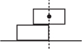
We have restricted ourselves to only allowing one on top of the other, since by constructing a cantilever structure such as

we can cover any horizontal distance we choose! Clearly this solution to the problem is not very interesting, and what we are really interested in solving is the problem of the maximum distance we can cover using a leaning stack. The stack must balance with only one domino per level. So how far horizontally can we get a tower of dominoes, one on top of the other, to lean? There are to be no counterbalancing or cantilever-type structures here!
Naturally, taking large dominoes we could obviously cover a large distance, so we think of the distance covered in units relative to the length of a single domino. Can we cover a distance twice the length? Three times? Hence we assume that the length of the block is 2 arbitrary units and that the block has mass 1: see figure 12.1. For now, the height and width of the dominoes will play no role. Let us assume that we have a leaning stack of n dominoes one on top of the other which leans to the right. We define cn to be the horizontal distance from the leftmost domino to the centre of mass of the stack.
To enlarge the stack we add another domino without destroying it, but this poses a problem. If we add a domino to the top the stack could break at any point, since none of the dominoes are glued together. To do this successfully we would need to check that at no point does the stack topple over.
A simpler way is to proceed by induction: placing the existing stack on top of the new domino making sure we do this in such a way that the centre of mass of the existing stack is above the new domino (see figure 12.2). So our strategy is this: at each stage we place the existing (balancing) stack on top of a new domino a distance δn from the left of the domino. There will clearly be no toppling if


Figure 12.2. Adding a domino at the top and bottom of the stack.
![]()
That is to say, we do not displace the top stack so far that the displacement plus the distance of the centre of mass from the left pushes the centre of mass over the edge of the bottom domino. The new centre of mass of the whole stack of n + 1 dominoes will be cn + 1 from the left of the bottom domino, where
![]()
As a check let us calculate what happens if we build a vertical tower with no displacement at all—that is to say, δn = 0 for all n. Then, from our relation above,
![]()
Given that c1 = 1 we see, by induction, that cn = 1 for all n also. So for a vertical stack, the centre of mass is always in the middle, as expected.
Let us push the dominoes as far as is theoretically possible. By this we mean we move the centre of mass so that it is right on the edge of the bottom domino. For two dominoes this means δ1 = 1 and we have the following configuration:
Remember that a domino will only topple if there is a positive rotational force generated by the centre of mass being over the edge. An arbitrary small clockwise tip will topple the stack in this situation, but for the moment, the fact that it balances in theory is sufficient.
To continue this we would need, this time, to choose
![]()
If we do this and derive our sequence for cn, we find that
![]()
Using this in (12.2) gives
![]()

Figure 12.3. Comparing the series 1/n with the function 1/(1+ x).
That is to say,
![]()
So the question becomes, what is the value of
![]()
for large N? Ideally we would like to let N → ∞, as we did in equation (6.3). The fact that each term in the infinite sum gets smaller, and ultimately converges to zero, gives us some hope that the infinite sum might total to a finite value. Actually, this hope is quite misplaced and what we have is a particularly famous series, known as the harmonic series. In the next section we will show that this series diverges. That is to say, it is possible to make the sum (12.3) as large as one would wish. In terms of the domino problem: we can chose displacements δn so that (i) the stack does not topple over and (ii) we can produce an arbitrarily large horizontal displacement. Bizarre indeed!
12.2 The Divergence of the Harmonic Series
The following medieval proof that the harmonic series diverges was discovered and published by Nicole d’Oresme (1323–82) around 1350 and relies on grouping the terms as follows:
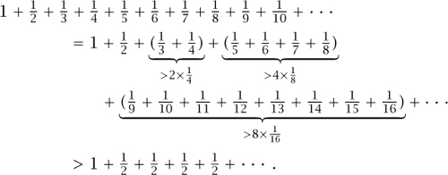
It follows that the series can be made arbitrarily large, although it diverges quite slowly.
Calculus, although unnecessary for our story, can also be used to provide an explicit estimate of the rate of growth by comparing the graph of a function with the terms of the series. In particular we compare terms in the series with the area under the graph of the function 1/(1 + x). Figure 12.3 should be enough to convince most people that
![]()
We need to recall general calculus theorems and the fact that
![]()
where the logarithm is the natural logarithm, i.e. a logarithm to the base e. In fact, in mathematics, (12.4) is usually taken to define the logarithm function. From this starting point logarithms to other bases can be defined and the rules of logarithms, such as (11.2), derived.
The integral can be solved giving
![]()
Now, the function In (1 + N) is unbounded so we can make the left-hand side of the above expression as large as we please by taking sufficiently large N. A similar argument comparing the series to the function 1/x shows that
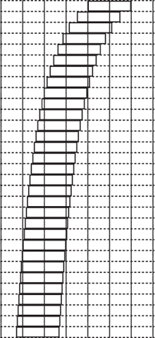
Figure 12.4. The diverging stack of dominoes.
![]()
so we can estimate how fast the series diverges.
12.3 Building the Stack of Dominos
It is perhaps inevitable that having realized that there is no theoretical limit to the potential horizontal distance that the stack of dominoes can cover we might like to see what it looks like. Can we really construct such a stack in practice and, if so, how would we do this?
Recall that our scheme for choosing δn was only one of many possibilities. If we choose δn to be as big as possible at each stage, then any small inaccuracy in our construction will doom our efforts to failure. Instead, a much safer practical approach is to choose δn to be consistently smaller than this, perhaps taking δn := 1/(2n). Instead of this simple scheme we choose δn to be
![]()
which is half the maximum possible distance to the toppling point. We call this a ‘50% stack’.
This is more conservative and the resulting stack is no longer exactly on the point of toppling. Taking this scheme, what is δn? And more importantly, what is the total horizontal distance given by δ1 + δ2 + ... + δN? Indeed, will we still be able to achieve an arbitrarily large displacement?
First let us calculate the cns explicitly under this scheme:
![]()
Now we set bn := 2 – cn and see what happens to the bns:

So, by induction,
![]()
However,
![]()
So we see that the total displacement is Σn δn and if we take N dominoes in the stack this exceeds
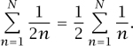
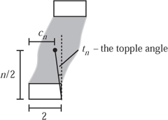
Figure 12.5. Toppling the stack.
What we really want is an explicit recurrence relation for δn and we can calculate this as follows:

Thus
![]()
Unfortunately this recurrence relation does not seem to have a simple closed-form solution.
Instead, we calculate successive values of δn numerically: these are shown in table 12.1. Notice also how close the value of cn gets to the critical value of 2, which is the value above which the stack will overbalance the bottom domino. If we use this recurrence relation and take blocks of length 2, we can construct the leaning tower shown in figure 12.4, where, for the purposes of illustration, the height is ![]() .
.
Given that cn approaches the critical value of 2 so closely, we examine the angle through which we would need to tip the whole stack, about the bottom corner, to topple it over.
The centre of mass of an object is fixed within an object regardless of how it is tipped or rotated. For our stack of dominoes this is cn from the left-hand edge of the bottom block, and therefore 2 – cn from the right-hand edge—this is illustrated in figure 12.5. We know that the blocks have length 2 but up to this point their height has played no role. We take the height of a block to be h so that the centre of mass is ![]() hn from the bottom of the stack. Thus we see that the angle of rotation tn needed to topple the stack is
hn from the bottom of the stack. Thus we see that the angle of rotation tn needed to topple the stack is
Table 12.1. The diverging stack of dominoes.
n |
cn |
δn |
tn |
1 |
1.000 |
0.500 |
75.964 |
2 |
1.250 |
0.375 |
56.310 |
3 |
1.417 |
0.292 |
37.875 |
4 |
1.531 |
0.234 |
25.115 |
5 |
1.613 |
0.194 |
17.223 |
6 |
1.672 |
0.164 |
12.339 |
7 |
1.717 |
0.142 |
9.201 |
8 |
1.751 |
0.125 |
7.097 |
9 |
1.778 |
0.111 |
5.630 |
10 |
1.800 |
0.100 |
4.569 |
11 |
1.818 |
0.091 |
3.781 |
12 |
1.833 |
0.083 |
3.179 |
13 |
1.846 |
0.077 |
2.710 |
14 |
1.857 |
0.071 |
2.337 |
15 |
1.867 |
0.067 |
2.036 |
16 |
1.875 |
0.062 |
1.790 |
17 |
1.882 |
0.059 |
1.586 |
18 |
1.889 |
0.056 |
1.414 |
19 |
1.895 |
0.053 |
1.270 |
20 |
1.900 |
0.050 |
1.146 |
21 |
1.905 |
0.048 |
1.039 |
22 |
1.909 |
0.045 |
0.947 |
23 |
1.913 |
0.043 |
0.866 |
24 |
1.917 |
0.042 |
0.796 |
25 |
1.920 |
0.040 |
0.733 |
![]()
Values for tn when h = ![]() (so the length of the block is four times the height) are also given in table 12.1 (in degrees).
(so the length of the block is four times the height) are also given in table 12.1 (in degrees).
This also illustrates the difference between stability and instability. Our scheme (12.6) gave rise to a stable stack—there exists a small but positive displacement through which you can tip the stack without toppling it. As Eisner (1959) comments:
To prove this result ‘physically’, a fellow graduate student and I stacked bound volumes of The Physical Review one evening, until an astonishingly large offset was obtained, and left them to be discovered the next morning by a startled physics librarian.
12.4 The Leaning Pencil and Reaching the Stars
Your intuition has probably rejected this result, and even if you accept the mathematics you may still harbour some doubts. While the result holds, your intuition is probably not that poor, and we shall now give a practical example to reassure you.
Suppose we wish to span a distance of 3 m with CD cases, which actually balance rather well. A CD case measures about 14 cm × 12 cm × 1 cm. So we want
![]()
where the left-hand side is in units of ‘half a CD case’, which is about 7 cm. So, including the units we need,
![]()
By the approximation (12.5) this gives
![]()
Now, the thickness of a CD case was taken to be 1 cm, so the height of the stack of CD cases needed to cover a horizontal distance of 3 m would be
4.1 × 10¹⁶ m = 4.3 light years
(one light year is 9.46 × 10¹⁵ m). If you tried to build it the gravitational attraction between the CD cases would probably be much more significant than the Earth’s gravitational pull on the CD cases, making the problem of ‘balance’ more tricky.

Figure 12.6. An unlikely looking, but nevertheless balancing, stack!
While CD cases, or even a pack of playing cards, are a good choice for a temporary model, it is also satisfying to glue wooden blocks in place. While this is not necessary from a theoretical point of view it does allow you to take the time to arrange the blocks into an impressive stack for illustrative purposes. The model shown in plate 24 was made from a length of ramin strip measuring 1 in × ![]() in (25 mm × 6.25 mm), which was obtained from a DIY shop. The wood takes a good finish and is hard enough for the complete model to withstand normal handling. The first stage in making a model such as this is to decide on the length of each tile. One unit equal to 25 mm or 1 in is a convenient scale. Then prepare a table of displacements δn, and again it is convenient to calculate them from
in (25 mm × 6.25 mm), which was obtained from a DIY shop. The wood takes a good finish and is hard enough for the complete model to withstand normal handling. The first stage in making a model such as this is to decide on the length of each tile. One unit equal to 25 mm or 1 in is a convenient scale. Then prepare a table of displacements δn, and again it is convenient to calculate them from
![]()
where f is the fractional approach to the balance point, so that when f = 0 a vertical tower results and when f = 1 the displacements become the harmonic series. Of course, there are other possibilities for δn provided each is less than or equal to 1/n. This is one instance where we found it easier to work with imperial measurements for δn and give the displacements directly in fractions of an inch.
Precision at every stage of construction is vital, otherwise the model will not meet expectations and will most probably fall over. With this in mind our strip was cut into lengths of 2 in, measured with Vernier callipers. It is essential to make a saw guide and use a fine-tooth razor saw. You can expect to waste several lengths before you are sure that the length is true, and even then it is worth checking each length as it is sawn off to make certain nothing has shifted. As with many jobs in a workshop it may well take more time to make the sawing fixture than to cut the actual pieces of wood. Any ragged ends left after sawing can be sanded off, and even here some precautions are necessary. Glue the paper to a flat piece of wood and only sand along the length of the tile before cleaning the end faces. Those with access to a small saw bench have a considerable advantage.
To build the model itself a top-down construction is needed. Start with the top pair of tiles and with a thin mixture of woodworking glue fix them together using the Vernier callipers to get the displacements exactly right. It is best to do this on a flat surface using a square to check they are in line on their sides. Cross out this step on your pre-prepared table of displacements and proceed to the next tile. After four or five tiles put the model on its side and sight along the upper corners to make sure everything lies on a smooth curve.
The challenge of this model is to see how tall you can make it, and as you can see from plate 25, we have managed thirty tiles with f = 50%. Our efforts with f = 70% and f = 90% are more modest. However tall you can reach, it is always satisfying when the top tile overhangs the base completely, as somehow this does not ‘look right’. Furthermore, we might be able, if we took very small blocks, to sand it down to give a smooth finish. We would then have a bent pencil-like wooden shape that potentially reaches as far as we like across the table but balances on its base.
12.5 Spiralling Out of Control
All the stacks described so far have been linear, in the sense that the longitudinal centre lines of individual tiles all lie on the same straight line in plan view. This is not a necessary condition for stability, however, as we shall show. Suppose the top n tiles are removed from a linear stack: the centre of mass then lies at a distance cn from the left-hand edge of the bottom tile. The whole stack is stable if this load of n tiles is placed on the (n + 1)th tile with its centre of mass at (δn + cn). At this stage nothing has been said about the particular arrangement of these top n tiles, only that the position of their centre of mass must be at cn, according to the protocol set out at the start of this chapter. The top part of the stack could be turned through 180º, as shown in figure 12.7, or indeed through any angle without loss of stability, as illustrated by plate 26.
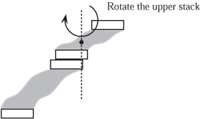
Figure 12.7. Rotating part of the stack in the horizontal plane.

Figure 12.8. Even this balances!
In principle a stack could be pivoted to swing at more than one level and through any angle, as in figure 12.8. There is, however, a practical problem. Pivot holes have to be drilled and as n increases their position becomes too close to the end of the tile beneath to be practicable. The purist would always make the pins of the same material as the tiles. In the model we used 1 mm plastic rod. The pivot pins bear no load except when the stacks are rotated.
We finish with a cautionary note. Our original intention was simply to build the tall stack shown in figure 12.4 using the calculated values in table 12.1. Once we had finished it, though, we found that we wanted to build others. So buy plenty of wood strips and retain your sawing jig for future use in case you too are tempted! Indeed, the recent article of Hall (2005) contains other possibilities we have yet to fully exploit.
12.6 Escaping from Danger
One reason why the harmonic series is so important in mathematics is that it illustrates the following result. Just because the terms in a sum converge to zero, the sum itself does not necessarily have a finite value. That is to say, while the sequence 1, ![]() ,
, ![]() , ... converges to zero, the sum 1 +
, ... converges to zero, the sum 1 + ![]() +
+ ![]() + ... is infinite. The following problem, posed by Alan Slomson, is one example of many and exploits the same mathematics that helped us stack dominoes.
+ ... is infinite. The following problem, posed by Alan Slomson, is one example of many and exploits the same mathematics that helped us stack dominoes.
Imagine a worm sitting on a 100 m long elastic tightrope. This worm moves at a constant speed of 1 m/s and merrily slithers along the rope, hoping to reach the other end. Yes, it’s a fast worm.
Unfortunately for the worm, a malevolent beast keeps stretching the rope instantaneously by 100 m at the end of every second. Note, the worm doesn’t stretch since it is a point-size worm. So, at the end of the first second the rope is now 200 m long. At the end of the second second, the worm has travelled another 1 m and the rope is now 300 m long.
When does the worm get to the end of the rope?
The situation appears hopeless, because the worm only moves 1 m before the rope becomes 100 m longer. However, remember that the rope behind the worm stretches as well as the rope in front. One way to think about this is to decide what fraction of the rope the worm has crossed in any given second. Thus in the first second it moves across one one-hundredth of the rope, during the second second, one two-hundredth, and in general it crosses a fraction 1/100N of the rope during the Nth second. The question becomes, when is
![]()
That is, when has the worm passed the end? Of course, we know that the harmonic series diverges and that
![]()
If In (1 + N) > 100, we will be done. Now, inverting each side gives N + 1 > e100 ≈ 2.7 × 1043 seconds. The short answer to the original question is ‘not soon’, but the worm will get to the end eventually.
12.7 Leaning Both Ways!
Despite the fact that we have been stacking up solid blocks, our problem was a fundamentally two-dimensional one. Originally we only stacked upwards and displaced the tower in one horizontal direction. While we rotated part of the stack around a vertical axis in section 12.4, there is a more interesting way to exploit the third dimension. This is to displace each block a distance δn in both of the horizontal directions simultaneously. If we take flat and square objects, rather then rectangular dominoes, we can construct a most implausible tower, such as that shown in figure 12.9.
What is so remarkable about this is that the top block has been displaced by (just under) a half in both horizontal directions. Hence, about three quarters of it appears to be unsupported. Nevertheless, this does actually work and a practical trial with CD cases is a pleasure not to be missed.

Figure 12.9. Leaning in two directions.
12.8 Self-Righting Stacks
In this section we shall assume that we have built a stack, but that this time all the dominoes are glued together. Stacks built according to the protocol just described can be said to be bistable. We are not concerned here with tipping sideways or backwards, only in the direction of the overhang. In their upright positions they are stable, but capable of withstanding only small disturbances before tipping over to a completely stable equilibrium. We now turn our attention to uni-stable stacks. That is to say, those for which the tipped-over position is unstable so that when the force that tipped them is removed they recover their original upright position. In other words, self-righting stacks. Almost inevitably these stacks are not as tall and need fewer tiles, but nevertheless they are interesting to make. It should be added that they still look as if they might tip quite easily.
The geometry needed to satisfy this new criterion is best illustrated by two examples shown in the sketch in figure 12.10. The stack with four tiles is uni-stable because when it is tipped over its centre of mass still lies to the left of the vertical y-axis, with the right-hand edge of the bottom tile at the origin O. When the force that tipped it is removed, the turning moment about the origin is anticlockwise and so the initial upright position is restored. When the five-tile stack is tipped, its centre of mass passes through the y-axis and since there is now no restoring moment it stays in that position in stable equilibrium: see plate 27.
Figure 12.10. Self-righting stacks.
The two crucial angles are
![]()
For the stack to be self-righting we require t1 + t2 < ![]() π, or 90º. This inequality looks like a typical engineering design problem to be satisfied with the two variables n and h and the δs. Replacing the inequalities by
π, or 90º. This inequality looks like a typical engineering design problem to be satisfied with the two variables n and h and the δs. Replacing the inequalities by
ε = ![]() π – t1 – t2
π – t1 – t2
still leaves a practical problem of the minimum value of ε that will ensure that the stack is self-righting without any external encouragement. All we can add is that the better the workmanship the smaller this angle can be: there is room here for the craftsman to experiment.
We can suggest further objectives: maximizing n or the total height nh, for example, or obtaining the greatest overhang or even the maximum value of h. All this strongly suggests a series of computer trials before making any model stacks. On a practical note, if the computed value of h is not a convenient size in terms of commercially available strip wood, the easiest solution is to use the nearest size and scale the unit length accordingly. As a final remark, we found that for a deck of playing cards the measured value is h ≈ 0.007. Not a tall stack, perhaps, but plenty of overhang.
12.9 Two-Tip Polyhedra
So far in this chapter we have considered the stability of an object when one flat face is placed on a table. Now we turn our attention to polyhedra and ask which faces are stable faces. That is to say, when a polyhedron is placed on a table on a particular face, does it tip over or not? The criterion used to determine whether a polyhedron will tip or not is identical to that used before. The centre of mass must be directly above the base when the shape is placed on the table. Equivalently, a face is stable if, and only if, the orthogonal projection of the centre of mass onto the face lies inside the face or on the edge. Throughout this discussion we shall assume that the object has flat (planar) faces, is made of a material which is uniform in density and is placed on a horizontal table.
Given a homogeneous polyhedron, at least one of the faces must be stable. If this were not the case, then none of the faces would be, and no matter how the object were placed on the table it would tip over onto another face, and then keep moving. We can appeal to the impossibility of perpetual motion to persuade you that this will not occur. At least one face is stable.
The simplest polyhedron has four sides: the tetrahedron. A regular tetrahedron, the familiar triangular pyramid, is stable on all its faces. In general, an irregular tetrahedron is always stable on the face that is closest to its centre of mass, since it can have no lower potential energy. In fact, a tetrahedron must have at least two stable faces.
Can we make one? In fact it is possible to construct a two-tip tetrahedron, which when placed lying on one of its faces will tip over to another face and then tip again, finally coming to rest on a third face. The following solution is given by Heppes (1967).
We assume that the tetrahedron is sitting on the table and label the four vertices as A, B, C and D as follows:
A = (–7, –8(1 – ε), 0),
B = (–1, 0, 0),
C = (1, 0, 0),
D = (7, 8, 8),
where 0 < ε < 1. Notice that it is the face ABC that sits on the table, with z = 0. The coordinates of the centre of mass, G, are given by
G = ![]() (A + B + C + D) = (0, 2ε, 2),
(A + B + C + D) = (0, 2ε, 2),
so the orthogonal projection of the centre of mass onto the table has (x, y) coordinates (0, 2ε), which lies outside the triangle ABC. Hence, the tetrahedron will tip on the edge BC, which lies on the x-axis. This involves a rotation of 45º, and the new coordinates are
A′ = (–7, –4![]() (1 – ε), 4
(1 – ε), 4 ![]() (1 – ε)),
(1 – ε)),
B′ = (–1, 0, 0),
C′ = (1, 0, 0),
D′ = (7, 4![]() , 0).
, 0).
Again, G′ = (0, ![]() (1 – ε), 0) lies outside the triangle B′C′D′ and so the tetrahedron must tip over once more. The freedom to choose ε gives many such two-tip tetrahedra—an example is shown in plate 28.
(1 – ε), 0) lies outside the triangle B′C′D′ and so the tetrahedron must tip over once more. The freedom to choose ε gives many such two-tip tetrahedra—an example is shown in plate 28.
12.10 Uni-Stable Polyhedra
For the tetrahedron, at least two faces are stable and there exist ‘two-tip’ tetraheda for which only two faces are stable. What about other polyhedra? We know all polyhedra have at least one stable face, but can we find an example of a convex polyhedron that will rest in a stable position on only one face? The implication of this would be that no matter how the object were placed on the table, it would roll around to its only stable face.
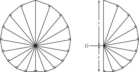
Figure 12.11. A cross-section of a uni-stable polyhedron.
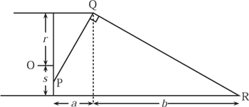
Figure 12.12. Truncating the prism.
It turns out that this is indeed possible and one solution, consisting of a polyhedron with nineteen faces, is given in Conway and Guy (1969). A physical model of this, in solid brass, is shown in plate 29. From personal discussions with John Conway, the authors believe that this is unique, and we shall now sketch exactly how it is constructed.
We begin the construction with a prism such as that shown in figure 12.11. Each half of this prism is made up of m right-angled triangles, each of the angles at the centre is equal and is therefore 180º/m. The hypotenuse of the largest triangle has length r = r0 and is vertical when the solid is in equilibrium. The other hypotenuses are rn = cosn(180º/m) for 0 < n < m, with s = rm = r cosm(180º/m) being collinear with r = r0. The ends of this prism are truncated obliquely as shown in figure 12.12, with two planar faces. We need to choose m, b and a sufficiently large so that the centre of mass lies below O but above P. The solid will then stand on only one lateral face, and on neither of the oblique ones. An involved calculation, in Conway and Guy (1969), shows that for m = 9 it is possible to achieve this provided that b is sufficiently large compared with a.