
Discontiguous Networks, Subnet 0, and Summarization Using IGRP
During the process of researching the material for this section, an anomaly was discovered in the behavior of IGRP. IGRP would install a summarized route for a major network when the router had a connection to a subnet of the same major net—which is not supposed to happen. Cisco engineers discovered this behavior while reviewing the material for this book prior to publication.
The Cisco engineers opened a bug against it—CSCdj03421— and fixed the bug so that IGRP now behaves as expected. In other words, it behaves now exactly as in the previous section on RIP. This bug has been integrated in IOS versions 11.0, 11.1 (and all 11.1-based releases), 11.2 (and all 11.2-based releases), and all releases that started shipping after IOS version 11.2 was first shipped.
Note
The remainder of this section should be treated as an exercise in analyzing anomalous behavior in a network and not as a representation of how IGRP really behaves.
The following two scenarios are presented in the remainder of this section:
Discontiguous networks using two routers
Discontiguous networks using three routers
Both routers have their configuration modified for running IGRP. The portion of the configuration for doing this in both routers is as follows:
!
router igrp 109
network 168.71.0.0
network 168.72.0.0
!
Recall that routers running IGRP examine the network number and mask associated with an interface before advertising routes from the routing table over it.
Discontiguous Networks Using Two Routers
Refer to Figure 3-10 for the network diagram used in this scenario. In the following output of the debug ip igrp transactions command from RouterB, you can see that RouterB advertises the major network of 168.71.0.0 to RouterA:
RouterB#deb ip igrp transactions
Oct 30 01:03:03: IGRP: sending update to 255.255.255.255 via Serial0 (168.72.6.2)
Oct 30 01:03:03:       network 168.71.0.0, metric=80125
Note
Variably subnetted means that the router has information that leads it to believe a major network address has been used with more than one mask. This is explained in more detail in Chapter 4 (in the section on VLSM). In the routing table from RouterA, major net 168.71.0.0 has two masks: 255.255.255.0 and 255.255.0.0.
In the following routing table from RouterA, you can see that RouterA believes that 168.71.0.0 is variably subnetted because of the local connection and the IGRP derived route from RouterB:
RouterA#show ip route
Codes: C - connected, S - static, I - IGRP, R - RIP, M - mobile, B - BGP
   D - EIGRP, EX - EIGRP external, O - OSPF, IA - OSPF inter area
   E1 - OSPF external type 1, E2 - OSPF external type 2, E - EGP
   i - IS-IS, L1 - IS-IS level-1, L2 - IS-IS level-2, * - candidate default

Gateway of last resort is 171.68.207.129 to network 10.0.0.0

S*   10.0.0.0 [1/0] via 171.68.207.129
     168.72.0.0 255.255.255.0 is subnetted, 1 subnets
C      168.72.6.0 is directly connected, Serial0
     168.71.0.0 is variably subnetted, 2 subnets, 2 masks
C       168.71.5.0 255.255.255.0 is directly connected, Ethernet0
I       168.71.0.0 255.255.0.0 [100/80188] via 168.72.6.2, 00:00:05, Serial0
RouterA#
In the following output from RouterA, you can see that RouterA can ping 168.71.0.1:
RouterA#ping 168.71.0.1
Type escape sequence to abort.
Sending 5, 100-byte ICMP Echos to 168.71.0.1, timeout is 2 seconds:
!!!!!
Success rate is 100 percent (5/5), round-trip min/avg/max = 4/4/4 ms
RouterA#
Recall that in the previous section on RIP, RouterA could not ping 168.71.0.1. For the next scenario, RouterC has been added to the network.
Discontiguous Networks Using Three Routers
This part of the scenario on using IGRP with discontiguous networks is split into additional sections:
When connectivity to subnet 0 is possible from RouterA
When connectivity to subnet 0 is not possible from RouterA
Alternating paths for the first ping
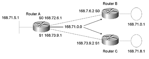
Figure 3-11 shows that RouterC, which is also running IGRP, has been returned to the network.
Figure 3-11. RouterC returns in the three-router scenario

Note
It is important to note that pings generated by a router are always pro cess -switched, regardless of the switching method configured on the out-bound interfaces. If parallel paths exist, the router should load share pings across the available paths.
When Connectivity Is Possible
In this section, RouterA is able to ping RouterB's Token Ring port (168.71.0.1), even though it is using subnet 0. RouterA can do this because it has a connection to the major net of 168.71.0.0, which it is advertising to RouterB and RouterC. Don't worry if you don't understand this yet. It should become clearer as this section progresses.
In the following routing table from RouterA, you can see that RouterA now has two summarized routes to 168.71.0.0:
RouterA#show ip route
Codes: C - connected, S - static, I - IGRP, R - RIP, M - mobile, B - BGP
   D - EIGRP, EX - EIGRP external, O - OSPF, IA - OSPF inter area
   E1 - OSPF external type 1, E2 - OSPF external type 2, E - EGP
   i - IS-IS, L1 - IS-IS level-1, L2 - IS-IS level-2, * - candidate default

Gateway of last resort is 171.68.207.129 to network 10.0.0.0

S*   10.0.0.0 [1/0] via 171.68.207.129
     168.72.0.0 255.255.255.0 is subnetted, 1 subnets
C      168.72.6.0 is directly connected, Serial0
     168.73.0.0 255.255.255.0 is subnetted, 1 subnets
C      168.73.9.0 is directly connected, Serial1
     168.71.0.0 is variably subnetted, 2 subnets, 2 masks
C      168.71.5.0 255.255.255.0 is directly connected, Ethernet0
I      168.71.0.0 255.255.0.0 [100/80188] via 168.72.6.2, 00:00:02, Serial0

							[100/80188] via 168.73.9.2, 00:00:10, Serial1
RouterA#
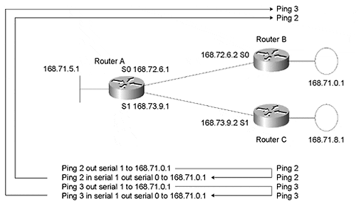
The arrows in Figure 3-12 show where these two routes point.
Figure 3-12. Router A's two Summarised routes to 168.71.0.0
In the following output of the show ip route 168.71.0.1 command from RouterA, you can see that RouterA uses the two summarized routes for 168.71.0.0 to reach 168.71.0.1:
RouterA#show ip route 168.71.0.1
Routing entry for 168.71.0.0 255.255.0.0
 Known via "igrp 109", distance 100, metric 80188
 Redistributing via igrp 109
 Advertised by igrp 109 (self originated)
 Last update from 168.73.9.2 on Serial1, 00:00:48 ago
 Routing Descriptor Blocks:
  168.72.6.2, from 168.72.6.2, 00:01:07 ago, via Serial0
   Route metric is 80188, traffic share count is 1
   Total delay is 20630 microseconds, minimum bandwidth is 128 Kbit
   Reliability 255/255, minimum MTU 1500 bytes
   Loading 1/255, Hops 0
 * 168.73.9.2, from 168.73.9.2, 00:00:48 ago, via Serial1
   Route metric is 80188, traffic share count is 1
   Total delay is 20630 microseconds, minimum bandwidth is 128 Kbit
   Reliability 255/255, minimum MTU 1500 bytes
Loading 1/255, Hops 0
RouterA#
In the following output of the ping command from RouterA, you can see that RouterA can ping 168.71.0.1 successfully 100 percent of the time:
RouterA#ping 168.71.0.1
Type escape sequence to abort.
Sending 5, 100-byte ICMP Echos to 168.71.0.1, timeout is 2 seconds:
!!!!!
Success rate is 100 percent (5/5), round-trip min/avg/max = 28/30/32 ms
RouterA#
Looking back at the routing table from RouterA, it appears that some of the pings should have been sent to RouterB and others to RouterC. This is based on the following two facts, which were introduced previously:
Pings generated by a router are always process-switched.
Routers load share on a packet-by-packet basis when parallel routes exist and when the packets are being process-switched.
So, in theory, the pings to RouterC should have failed because RouterC doesn't own IP address 168.71.0.1—RouterB does.
The three possible reasons why these pings were successful are as follows:
RouterA sent all of the pings to RouterB, even though it shouldn't have. This would have been a bug in the behavior of switching ping packets generated by the router itself.
RouterC responded to the pings as if it owned 168.71.0.1. Because RouterC doesn't have an interface with 168.71.0.1 configured on it, this would have required a major bug in RouterC's operating system. (Note: it is possible to configure the same IP address in two or more routers by mistake. It is never a good idea.)
RouterC was receiving the pings for 168.71.0.1 from RouterA and forwarding them back to RouterA. RouterA in turn forwarded them back to RouterC.
Fortunately, the answer is the last scenario: RouterC was forwarding them back to RouterA. The remainder of this section proves that this was the case.
The following output of the debug ip packet command is from RouterA as it sends five pings to 168.71.0.1. The output shows that some of the pings went out serial 1 to RouterC first and that RouterC sent them back to RouterA. RouterA then forwarded its own pings to RouterB. The ping command itself (RouterA#ping 168.71.0.1) and its related messages have been omitted for clarity.
Note
The pings are numbered (1), (2), (3), (4), and (5) so that you can see which events go together.
RouterA#debug ip packet

							(1) IP: s=168.72.6.1 (local), d=168.71.0.1 (Serial0), len 100, sending
(1) IP: s=168.71.0.1 (Serial0), d=168.72.6.1 (Serial0), len 104, rcvd 3
(2) IP: s=168.72.6.1 (local), d=168.71.0.1 (Serial1), len 100, sending
(2) IP: s=168.72.6.1 (Serial1), d=168.71.0.1 (Serial0), g=168.72.6.2, len 104, forward
(2) IP: s=168.71.0.1 (Serial0), d=168.72.6.1 (Serial0), len 104, rcvd 3
(3) IP: s=168.72.6.1 (local), d=168.71.0.1 (Serial1), len 100, sending
(3) IP: s=168.72.6.1 (Serial1), d=168.71.0.1 (Serial0), g=168.72.6.2, len 104, forward
(3) IP: s=168.71.0.1 (Serial0), d=168.72.6.1 (Serial0), len 104, rcvd 3
(4) IP: s=168.72.6.1 (local), d=168.71.0.1 (Serial1), len 100, sending
(4) IP: s=168.72.6.1 (Serial1), d=168.71.0.1 (Serial0), g=168.72.6.2, len 104, forward
(4) IP: s=168.71.0.1 (Serial0), d=168.72.6.1 (Serial0), len 104, rcvd 3
(5) IP: s=168.72.6.1 (local), d=168.71.0.1 (Serial1), len 100, sending
(5) IP: s=168.72.6.1 (Serial1), d=168.71.0.1 (Serial0), g=168.72.6.2, len 104, forward
(5) IP: s=168.71.0.1 (Serial0), d=168.72.6.1 (Serial0), len 104, rcvd 3
RouterA#
The following text illustrates these steps:
The first ping (1) is sent out serial 0 to RouterB, and a response is received immediately.
Pings (2), (3), (4), and (5) take the other available path to 168.71.0.0 via serial 1 to RouterC.
RouterC forwards pings (2), (3), (4), and (5) back to RouterA.
RouterA forwards them on to RouterB.
Finally, RouterB responds to the pings.
This is exactly what should happen based on RouterA load sharing packets to 168.71.0.1 between serial 0 and serial 1. The next section explains in more detail the path that pings (2) and (3) take through the network.
Note
The remainder of this section explains the behavior just demonstrated. If you are comfortable with this material, feel free to skip this section and pick up at the next section, "When Connectivity Is Not Possible."
You now know that RouterC was forwarding RouterA's pings back to RouterA. You can explore the same issue from a more graphical point of view. In Figure 3-13, RouterA is load balancing between the two paths. Ping (2) goes out serial 0 to RouterC. RouterC does a longest match lookup and sees that 168.71.0.1 matches 168.71.0.0 that is known via serial 1 using RouterA.
RouterC forwards ping (2) back to RouterA. This is the second packet that RouterA has seen for the destination 168.71.0.1 (the first was when it sent ping (2) in the first place), so RouterA sends ping (2) out the next available path—serial 0 to RouterB.
Figure 3-13. Router A is load balancing between the two paths
In the following portion from the previous debug output, you can see RouterA load balancing between the two paths for pings, (1) and (2). The lines showing the two different paths are in bold.
1) IP: s=168.72.6.1 (local), d=168.71.0.1 (Serial0), len 100, sending
1) IP: s=168.71.0.1 (Serial0), d=168.72.6.1 (Serial0), len 104, rcvd 3
2) IP: s=168.72.6.1 (local), d=168.71.0.1 (Serial1), len 100, sending
2) IP: s=168.72.6.1 (Serial1), d=168.71.0.1 (Serial0), g=168.72.6.2, len 104, forward
2) IP: s=168.71.0.1 (Serial0), d=168.72.6.1 (Serial0), len 104, rcvd 3
At the beginning of this section, you looked at RouterA's routes to 168.71.0.0. Now that you have seen how the network behaves, let's review the routing tables from RouterB and RouterC to understand why pings to 168.71.0.1 were routed as they were.
Following is RouterB's routing table, showing the summarized route to 168.71.0.0 that RouterA is advertising to it:
RouterB#show ip route
Codes: C - connected, S - static, I - IGRP, R - RIP, M - mobile, B - BGP
   D - EIGRP, EX - EIGRP external, O - OSPF, IA - OSPF inter area
   E1 - OSPF external type 1, E2 - OSPF external type 2, E - EGP
   i - IS-IS, L1 - IS-IS level-1, L2 - IS-IS level-2, * - candidate default

Gateway of last resort is 168.72.6.1 to network 10.0.0.0

I*   10.0.0.0 [100/160250] via 168.72.6.1, 00:00:49, Serial0
    168.72.0.0 255.255.255.0 is subnetted, 1 subnets
C     168.72.6.0 is directly connected, Serial0
I   168.73.0.0 [100/82125] via 168.72.6.1, 00:00:49, Serial0
168.71.0.0 is variably subnetted, 2 subnets, 2 masks
I       168.71.0.0 255.255.0.0 [100/10002001] via 168.72.6.1, 00:00:49, Serial0
C       168.71.0.0 255.255.255.0 is directly connected, TokenRing0
RouterB#
HINTS
Using a full IP host address with the show ip route command is a good habit to get into. It ensures that the route displayed is the longest match in the routing table.
The following output of the show ip route 168.71.0.1 command from RouterB shows that RouterB will use its route to 168.71.0.0 via RouterA to forward packets addressed to 168.71.0.1:
RouterB#show ip route 168.71.0.1
Routing entry for 168.71.0.0 255.255.0.0
 Known via "igrp 109", distance 100, metric 10002001
 Redistributing via igrp 109
 Last update from 168.72.6.1 on Serial0, 00:00:04 ago
 Routing Descriptor Blocks:
 *168.72.6.1, from 168.72.6.1, 00:00:04 ago, via Serial0
  Route metric is 10002001, traffic share count is 1
  Total delay is 20010 microseconds, minimum bandwidth is 1 Kbit
  Reliability 255/255, minimum MTU 1500 bytes
  Loading 1/255, Hops 0
RouterB#
Following is RouterC's routing table, which shows the summarized route to 168.71.0.0 that RouterA is advertising to it:
RouterC#show ip route
Codes: C - connected, S - static, I - IGRP, R - RIP, M - mobile, B - BGP
   D - EIGRP, EX - EIGRP external, O - OSPF, IA - OSPF inter area
   E1 - OSPF external type 1, E2 - OSPF external type 2, E - EGP
   i - IS-IS, L1 - IS-IS level-1, L2 - IS-IS level-2, * - candidate default

Gateway of last resort is 168.73.9.1 to network 10.0.0.0

I* 10.0.0.0 [100/160250] via 168.73.9.1, 00:00:55, Serial1
I  168.72.0.0 [100/82125] via 168.73.9.1, 00:00:55, Serial1
   168.73.0.0 255.255.255.0 is subnetted, 1 subnets
C    168.73.9.0 is directly connected, Serial1
168.71.0.0 is variably subnetted, 2 subnets, 2 masks
C    168.71.8.0 255.255.255.0 is directly connected, TokenRing0
I    168.71.0.0 255.255.0.0 [100/10002001] via 168.73.9.1, 00:00:56, Serial1
RouterC#
Again, you can test whether the router will match the full IP host address (168.71.0.1) to the route:
RouterC#show ip route 168.71.0.1
Routing entry for 168.71.0.0 255.255.0.0
 Known via"igrp 109", distance 100, metric 10002001
 Redistributing via igrp 109
 Last update from 168.73.9.1 on Serial1, 00:01:09 ago
 Routing Descriptor Blocks:
 *168.73.9.1, from 168.73.9.1, 00:01:09 ago, via Serial1
  Route metric is 10002001, traffic share count is 1
  Total delay is 20010 microseconds, minimum bandwidth is 1 Kbit
  Reliability 255/255, minimum MTU 1500 bytes
  Loading 1/255, Hops 0
RouterC#
When Connectivity Is Not Possible
In the previous section, RouterA was able to ping 168.71.0.1 100 percent of the time. It was able to do so because it was advertising the summarized route of 168.71.0.0 for its connection to 168.71.5.0 to RouterB and RouterC. RouterC used this summarized route to forward packets destined for 168.71.0.1 that were received from RouterA back to RouterA so that RouterA could forward them over the next available path to RouterB.
In Figure 3-14, RouterA no longer has a connection to a subnet of the 168.71.0.0 network, so it does not advertise the summarized route to RouterB and RouterC. RouterA still has two summarized routes to 168.71.0.0 via RouterB and RouterC. However, RouterA can no longer ping 168.71.0.1 100 percent of the time.
Figure 3-14. Router A no longer has a connection to a subnet of the 168.7.0.0 network.

RouterB and RouterC are summarizing their local subnets of 168.71.0.0 because of the different major network applied to their serial interfaces. However, RouterA will not forward these entries to RouterB and RouterC due to a split horizon. (Recall that the term split horizon means not advertising routes back out the interface they were learned over.)
RouterA's new routing table shows the summarized routes to 168.71.0.0 and no local connection to 168.71.0.0:
RouterA#show ip route
Codes: C - connected, S - static, I - IGRP, R - RIP, M - mobile, B - BGP
   D - EIGRP, EX - EIGRP external, O - OSPF, IA - OSPF inter area
   E1 - OSPF external type 1, E2 - OSPF external type 2, E - EGP
   i - IS-IS, L1 - IS-IS level-1, L2 - IS-IS level-2, * - candidate default

Gateway of last resort is 171.68.207.129 to network 10.0.0.0

S*  10.0.0.0 [1/0] via 171.68.207.129
  168.72.0.0 255.255.255.0 is subnetted, 1 subnets
C    168.72.6.0 is directly connected, Serial0
  168.73.0.0 255.255.255.0 is subnetted, 1 subnets
C    168.73.9.0 is directly connected, Serial1
  168.74.0.0 255.255.255.0 is subnetted, 1 subnets
C    168.74.5.0 is directly connected, Ethernet0
I  168.71.0.0 [100/80188] via 168.72.6.2, 00:00:42, Serial0
		 [100/80188] via 168.73.9.2, 00:00:04, Serial1
RouterA#
RouterB's new routing table shows the local connection to 168.71.0.0 and no summarized routes to 168.71.0.0:
RouterB#show ip route
Codes: C - connected, S - static, I - IGRP, R - RIP, M - mobile, B - BGP
   D - EIGRP, EX - EIGRP external, O - OSPF, IA - OSPF inter area
   E1 - OSPF external type 1, E2 - OSPF external type 2, E - EGP
   i - IS-IS, L1 - IS-IS level-1, L2 - IS-IS level-2, * - candidate default

Gateway of last resort is 168.72.6.1 to network 10.0.0.0

I* 10.0.0.0 [100/160250] via 168.72.6.1, 00:00:56, Serial0
  168.72.0.0 255.255.255.0 is subnetted, 1 subnets
C   168.72.6.0 is directly connected, Serial0
I 168.73.0.0 [100/82125] via 168.72.6.1, 00:00:56, Serial0
I 168.74.0.0 [100/10002001] via 168.72.6.1, 00:00:56, Serial0
168.71.0.0 255.255.255.0 is subnetted, 1 subnets
C    168.71.0.0 is directly connected, TokenRing0
RouterB#
In this output of show ip route 168.71.0.0 from RouterB, you can see RouterB's connected route to 168.71.0.0. There is no summarized route to 168.71.0.0:
RouterB#show ip route 168.71.0.0
Routing entry for 168.71.0.0 255.255.255.0, 1 known subnets
 Attached (1 connections)
 Redistributing via igrp 109
 Advertised by igrp 109

C   168.71.0.0 is directly connected, TokenRing0
RouterB#
RouterC's new routing table shows the local connection to 168.71.8.0 and no summarized routes to 168.71.0.0:
RouterC#show ip route
Codes: C - connected, S - static, I - IGRP, R - RIP, M - mobile, B - BGP
   D - EIGRP, EX - EIGRP external, O - OSPF, IA - OSPF inter area
   E1 - OSPF external type 1, E2 - OSPF external type 2, E - EGP
   i - IS-IS, L1 - IS-IS level-1, L2 - IS-IS level-2, * - candidate default

Gateway of last resort is 168.73.9.1 to network 10.0.0.0

I* 10.0.0.0 [100/160250] via 168.73.9.1, 00:00:35, Serial1
I 168.72.0.0 [100/82125] via 168.73.9.1, 00:00:35, Serial1
  168.73.0.0 255.255.255.0 is subnetted, 1 subnets
C   168.73.9.0 is directly connected, Serial1
I 168.74.0.0 [100/10002001] via 168.73.9.1, 00:00:35, Serial1
168.71.0.0 255.255.255.0 is subnetted, 1 subnets
C    168.71.8.0 is directly connected, TokenRing0
RouterC#
In this output of show ip route 168.71.0.0 from RouterC, you can see RouterC is connected to 168.71.8.0. There is no summarized route to 168.71.0.0:
RouterC#show ip route 168.71.0.0
Routing entry for 168.71.0.0 255.255.255.0, 1 known subnets
 Attached (1 connections)
 Redistributing via rip, igrp 109
 Advertised by igrp 109

C       168.71.8.0 is directly connected, TokenRing0
RouterC#
In this configuration, you can see that RouterA is only 60 percent successful pinging 168.71.0.1:
RouterA#ping 168.71.0.1
Type escape sequence to abort.
Sending 5, 100-byte ICMP Echos to 168.71.0.1, timeout is 2 seconds:
!U!.!
Success rate is 60 percent (3/5), round-trip min/avg/max = 4/4/4 ms
RouterA#
In this output from the debug ip packet and debug ip icmp commands from RouterA, taken while pinging 168.71.0.1, you can see that pings (1), (3), and (5) are successful:
RouterA#debug ip packet
RouterA#debug ip icmp
(1) IP: s=168.72.6.1 (local), d=168.71.0.1 (Serial0), len 100, sending
(1) IP: s=168.71.0.1 (Serial0), d=168.72.6.1 (Serial0), len 104, rcvd 3
(1) ICMP: echo reply rcvd, src 168.71.0.1, dst 168.72.6.1
(2) IP: s=168.72.6.1 (local), d=168.71.0.1 (Serial1), len 100, sending
(2) IP: s=168.73.9.2 (Serial1), d=168.72.6.1, len 60, rcvd 4
(2) ICMP: dst (168.72.6.1) host unreachable rcv from 168.73.9.2
(3) IP: s=168.72.6.1 (local), d=168.71.0.1 (Serial0), len 100, sending
(3) IP: s=168.71.0.1 (Serial0), d=168.72.6.1 (Serial0), len 104, rcvd 3
(3) ICMP: echo reply rcvd, src 168.71.0.1, dst 168.72.6.1
(4) IP: s=168.72.6.1 (local), d=168.71.0.1 (Serial1), len 100, sending
(5) IP: s=168.72.6.1 (local), d=168.71.0.1 (Serial0), len 100, sending
(5) IP: s=168.71.0.1 (Serial0), d=168.72.6.1 (Serial0), len 104, rcvd 3
(5) ICMP: echo reply rcvd, src 168.71.0.1, dst 168.72.6.1
RouterA#
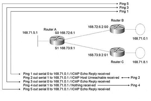
Figure 3-15 shows the paths that the pings in this example took through the network.
Figure 3-15. A graphical representation of the paths used by the pings in this example.
Note
debug ip icmp allows you to see exactly what ICMP messages are being received. Note that only one ICMP Host Unreachable is sent to RouterA. Having the routers limit ICMP Host Unreachable messages to hosts (in this case RouterA) that send more than one IP packet to an unreachable host over a short period of time keeps routers from being overwhelmed by the task of creating and sending the ICMP messages.
In the debug messages from RouterA, the ICMP host unreachable message from RouterC is in response to ping (2). RouterC does not send an IP ICMP unreachable message for ping (4) because routers protect themselves from having to respond to too many packets for unreachable hosts by ignoring some of them. Otherwise, malicious people could tie up a router's CPU by barraging the router with packets to unreachable hosts.
The following extract from the output of the debug ip packet and debug ip icmp commands from RouterC shows only the messages related to the packets RouterA sent to RouterC:
RouterC#debug ip packet
RouterC#debug ip icmp
(2) IP: s=168.72.6.1 (Serial1), d=168.71.0.1, len 104, unroutable
(2) ICMP: dst (168.71.0.1) host unreachable sent to 168.72.6.1
(2) IP: s=168.73.9.2 (local), d=168.72.6.1 (Serial1), len 32, sending
(4) IP: s=168.72.6.1 (Serial1), d=168.71.0.1, len 104, unroutable
RouterC#
Alternating Paths for the First Ping
If you stage a scenario like the previous one in a lab, you will notice that the number of successful pings will be inconsistent from one test to another. This is because when a router believes that it has two or more viable paths to a destination, it will alternate between them when sending the first ping. The remainder of this section explains this phenomenon in more detail. This behavior is not related to the routing protocol in use.
The following output from RouterA shows that RouterA will alternate which route to 168.71.0.0 it uses first so that the failures will vary from time to time.
Using serial 1 first results in the following output:
RouterA#ping 168.71.0.1
Type escape sequence to abort.
Sending 5, 100-byte ICMP Echos to 168.71.0.1, timeout is 2 seconds:
U!.!U
Success rate is 40 percent (2/5), round-trip min/avg/max = 4/4/4 ms
Using serial 0 first results in the following output:
RouterA#ping 168.71.0.1
Type escape sequence to abort.
Sending 5, 100-byte ICMP Echos to 168.71.0.1, timeout is 2 seconds:
!U!.!
Success rate is 60 percent (3/5), round-trip min/avg/max = 4/4/4 ms
RouterA#
This is normal load-balancing behavior. The percentage of successful pings varies, depending on which interface is selected first.
Using Other Routing Protocols
It is possible to create very similar problems to those just presented using IP routing protocols that allow for discontiguous networks, such as EIGRP, RIP V2, and OSPF. You can create a situation in which one remote location is advertising a summarized major net and another site is advertising subnet 0 for the same major net. The results will be very similar to the results documented here.
For example, suppose you are using EIGRP. If RouterA has a route via RouterB to 168.71.0.0 with a mask of 255.255.0.0, and another route for 168.71.0.0 with a mask of 255.255.255.0 via RouterC, you may find that packets you intend to reach RouterB (168.71.0.1) end up at RouterC. This may take place because it is a longer match (the mask is longer, so there are more bits to compare to the destination IP address).
This section introduced a new debug command, debug ip icmp, as well as some interesting packet-forwarding behavior. Pings were successful in some cases—but not always by using the most obvious path. Remember that the section on IGRP is only applicable in real life if you are running a version of Cisco IOS that doesn't have the fix—CSCdj03421.
The next section discusses how summarization can be used as a network design tool when creating complex IP networks.