Understanding Topology and Router Configurations
This section contains the original router configurations used for most of the examples in this book. Any time a change is made to one of these configurations in a subsequent chapter, a note is provided indicating what was changed and why.
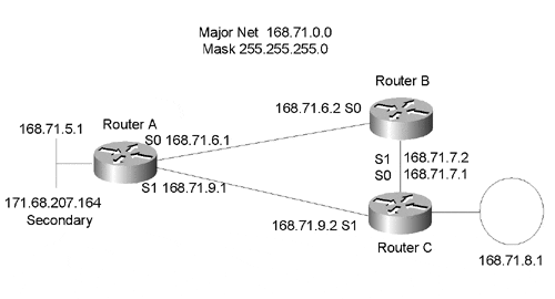
Figure 1-4 shows the basic topology used unless otherwise noted. This three-router design uses the minimum number of routers required to present some fairly complex concepts. Adding additional routers is only necessary in a few instances, in which three routers are not sufficient to create a particular scenario.
Figure 1-4. Basic topology for most scenarios.

In the network diagrams, SO and SI are used as shorthand for Serial Interface 0 and Serial Interface I, respectively.
Note
RouterA as used in this chapter has a connection to the "real" Cisco network via its secondary address. Secondary addresses allow an interface to participate in more than one IP network at the same time. Although the secondary address space may not be mentioned again, look for references to it in the sections on summarization, default routes, and other issues that require access to networks the routers do not know explicitly.
RouterA's Configuration
The configuration for RouterA is as follows:
!
interface ethernet0
ip address 168.71.5.1 255.255.255.0
ip address 171.68.207.164 255.255.128 secondary
!
interface serial0
ip address 168.71.6.1 255.255.255.0
bandwidth 128
!
interface serial1
ip address 168.71.9.1 255.255.255.0
bandwidth 128
!
router rip
network 168.71.0.0
passive-interface Ethernet0
!
ip route 0.0.0.0 0.0.0.0 Ethernet0
!
This is the configuration for RouterA that is used in all future examples and scenarios unless otherwise noted. RouterA is running RIP. It is configured with a passive interface Ethernet0 command that prevents RIP from advertising routing updates out Ethernet0, which is a connection to Cisco's corporate network.
Note
The addresses used in the examples and scenarios in this book are not part of Cisco's registered range of IP addresses. They were chosen entirely at random and may be assigned to another organization. For more information on using registered and unregistered IP addresses, see RFC 1918: "Address Allocation for Private Internets."
If RouterA inadvertently advertised the unregistered networks it has configured or learned from RouterB and RouterC to other Cisco routers, they might in turn advertise the networks to the Internet. If these addresses were actually in use by another organization, it is highly likely that some or all of the traffic for these networks would be directed from the Internet to Cisco. Users should always be aware of where a router will advertise its routes and, when necessary, prevent routing advertisements for certain networks to avoid connectivity problems caused by advertising false routes.
RouterB's Configuration
RouterB's configuration is very simple. RouterB only has two WAN interfaces, which is not a very common configuration. However, it does provide sufficient connectivity for most of the scenarios in this book. Adding additional interfaces would add unnecessary complexity.
RouterB has two bandwidth statements. This will affect any scenario using IGRP because IGRP used the bandwidth statement as part of the algorithm for determining routing metrics.
The configuration for RouterB is as follows:
!
interface serial0
ip address 168.71.6.2 255.255.255.0
bandwidth 128
!
interface serial1
ip address 168.71.7.2 255.255.255.0
bandwidth 64
!
router rip
network 168.71.0.0
!
RouterC's Configuration
RouterC has a Token Ring interface instead of an Ethernet interface. This interface is used to demonstrate that when routing protocols such as IP, IPX, and AppleTalk are used in conjunction with different types of LANs, routers automatically take care of creating the proper layer two packet and addressing formats for the destination interface.
RouterC also has two bandwidth statements. This will affect any scenario using IGRP because IGRP used the bandwidth statement as part of the algorithm for determining routing metrics.
The configuration for RouterC is as follows:
!
interface tokenring0
ip address 168.71.8.1 255.255.255.0
!
interface serial0
ip address 168.71.7.1 255.255.255.0
bandwidth 64
!
interface serial1
ip address 168.71.9.2 255.0.0.0
bandwidth 128
!
router rip
network 168.71.0.0
!
The previous sections introduced the concept of where routers can be deployed in a network and what types of functions they can perform. The format of IP addresses; as well as some possible issues when bridging routable protocols such as IP, IPX, and AppleTalk; were also introduced. Finally, the basic configurations used for the routers in many of the scenarios presented later in this book were provided. The next section goes into more detail on how routers forward packets through a network.
