Using End Systems with Multiple Local Gateways
Currently, it is not uncommon for an end system to have more than one local gateway. Unfortunately, this is one of the weakest areas of IP routing. It is readily apparent that, when the concept of IP gateways for end systems was being considered by those writing IP protocol stacks, it was not common to have more than one local gateway.
In Figure 5-19, the PC on the Token Ring has two possible gateways to reach 168.71.5.0. Because most PCs running Windows are not usually running a dynamic routing protocol, they are restricted to using a single gateway at a time. In this case, the PC can use either RouterB or RouterC to reach 168.71.5.0—but not both. If RouterA failed while a PC was using it, the PC would have to be reconfigured to use RouterB.
Figure 5-19. A review of the three-router topology.

In addition, the PC cannot load balance traffic between the two routers, even though the links connecting the routers have the same amount of bandwidth (both 56k or T1).
Traffic from the PC on the Ethernet is load balanced because RouterA has two parallel links that are considered to be of equal cost in this example. Note that this PC has only one gateway.
In an ideal world, end systems would be able to dynamically learn how many gateways were available off of their local network, what remote networks each gateway could reach, and the operational status of any gateways.
ICMP Router Discovery Protocol (IRDP) RFC 1256
IRDP RFC 1256 is the ICMP Router Discovery Protocol that runs on routers and end systems so that routers can advertise themselves to end stations and end stations can listen to the advertisements. By listening to these advertisements, end stations can dynamically select a gateway for reaching non-local networks. RFC 1256 allows one router to be preferred over another and provides other options for controlling the behavior of systems running IRDP.
The simplest configuration commands for IRDP in a Cisco router are as follows:
!
interface tokenring0
ip address 168.71.8.1 255.255.255.0
ip irdp
!
A thorough discussion of RFC 1256 is beyond the scope of this book. See the Cisco IOS documentation for the version of IOS you are using for more information on Cisco's implementation of IRDP.
This RFC is available on any site that makes RFCs available via anonymous FTP. It can be found on Cisco's CCO FTP server as follows: FTP to cco.cisco.com username=anonymous, pass word=your_full_email_address. The FTP client must run in passive mode. (FTP server assigns the client's FTP port for the session. Go to /pub/rfc/RFC.)
End Systems Using RIP
End systems that can run RIP are somewhat better off. They can listen to routing updates and react to changes in the network accordingly. However, RIP V1 on an end system shares all of the limitations of RIP V1 on a router—no VLSM support, no discontiguous network support, and no capability to understand the actual speed of any network so that two parallel links are always of equal cost even when they are different bandwidths (one 56k and one T1).
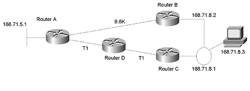
In Figure 5-20, the end system on the Token Ring could determine that the path to 168.71.5.0 via RouterB has only one hop, while the path has two. Unfortunately, RIP V1 can't understand that the bandwidth of the one-hop path is much slower, making the two-hop path a better path.
Figure 5-20. The one-hop path is slower than the two-hop path.

In Figure 5-20, RouterA thinks that the one-hop path via RouterB to 168.71.8.0 is faster than the two-hop path via RouterD and RouterC, even though the actual speed of the links between RouterA, RouterD, and RouterC is significantly faster than the link between RouterA and RouterB.
One issue with running RIP, or any dynamic routing protocols on end systems, is that it can result in a lot of routing updates being sent on LANs.
In Figure 5-21, all links are now the same bandwidth. However, the network administrator doesn't want to send all routing information onto the LANs, so the end system cannot figure out for itself that RouterB is the preferred gateway. A candidate default—0.0.0.0—is sent by both routers. The router with the better path—RouterB—has a better default metric configured—in this case, 1 versus 2. It is possible to configure a default metric for use by RIP for the 0.0.0.0 route.
Figure 5-21. Using 0.0.0.0 with different metrics.

The following configurations from RouterB and RouterC show how to make this work:
!
hostname RouterB
!
ip subnet-zero
!
interface serial0
ip address 168.71.6.2 255.255.255.0
!
interface serial1
shutdown
!
interface tokenring0
ip address 168.71.8.2 255.255.255.0
!
router rip
network 168.71.0.0
redistribute static
default-metric 1
distribute-list 1 out tokenring0
distribute-list 2 out serial0
!
ip route 168.71.0.0 255.255.255.0 null0
ip route 0.0.0.0 0.0.0.0 null0
!
access-list 1 permit 0.0.0.0 0.0.0.0
access-list 1 permit 168.71.0.0 0.0.0.0
access-list 2 deny 0.0.0.0 0.0.0.0
access-list 2 deny 168.71.0.0 0.0.0.0
access-list 2 permit 0.0.0.0 255.255.255.255
!
For RIP V1 and IGRP, the static route to 168.71.0.0 must have the same mask as the Token Ring interface in order for it to be advertised over the Token Ring. (See the VLSM section for more details.) Therefore, the ip subnet-zero command must be configured when using RIP V1 and IGRP because the static route 168.71.0.0 255.255.255.0 is pointing at subnet 0 of the 168.71.0.0 major net. This command enables you to use ip subnet-zero in a router for static routes or as a subnet on an interface.
The distribute lists ensure that only the 0.0.0.0 and 168.71.0.0 routes are advertised out the Token Ring and that these two routes are not advertised out the serial interfaces.
The access lists are used by the distribute lists. The default metric command is used to ensure that the static routes to 0.0.0.0 and 168.71.0.0 advertised by RouterB are preferred over the same routes advertised by RouterC. RouterC uses a default metric of 2.
!
hostname RouterC
!
ip subnet-zero
!
interface serial0
shutdown
!
interface serial1
ip address 168.71.9.2 255.255.255.0
!
interface tokenring0
ip address 168.71.8.2 255.255.255.0
!
router rip
network 168.71.0.0
redistribute static
default-metric 2
distribute-list 1 out tokenring0
distribute-list 2 out serial1
!
ip route 168.71.0.0 255.255.255.0 null0
ip route 0.0.0.0 0.0.0.0 null0
!
access-list 1 permit 0.0.0.0 0.0.0.0
access-list 1 permit 168.71.0.0 0.0.0.0
access-list 2 deny 0.0.0.0 0.0.0.0
access-list 2 deny 168.71.0.0 0.0.0.0
access-list 2 permit 0.0.0.0 255.255.255.255
!
Cisco's Hot Standby Router Protocol (HSRP)
Hot Standby Router Protocol ( HSRP) is a Cisco proprietary protocol for handling multiple gateways on a LAN. It does so by having the gateways share an IP address and a MAC address. One of the gateway's interfaces to the common LAN is in STANDBY mode, while the other's interface is in ACTIVE mode. In the event that the ACTIVE interface or router goes down, the STANDBY interface goes live.
Routers configured for HSRP send information to each other indicating that they will receive even if their interface is in standby mode. This is accomplished by using special functional MAC addresses reserved only for HSRP packets. A router whose interface is in standby mode accepts frames addressed to this MAC address, ignoring all other frames.
HINT
A router configured for HSRP uses its original IP address and MAC address on the interface, as well as the Hot Standby IP address and special MAC address when they are active. Therefore, it is possible to use the original IP addresses for Telnet sessions and SNMP monitoring even when the router is the active HSRP router. In addition, the Hot Standby IP address and the MAC address can be active on only one router at a time.
In Figure 5-22, the end system has two gateways but can use only one at a time. Without HSRP, the end system would have to be reconfigured if the default gateway it was configured for failed. With HSRP, the router with the standby interface learns about the failure of the other gateway because that gateway has ceased sending HSRP packets. This router places its interface into forwarding mode.
Because the HSRP routers are acting as if their interfaces have the same IP address—in this case, 168.71.8.3—and MAC address, the end system keeps using the gateway IP address it was configured with, as well as the MAC address it ARPed for. Remember that the layer two MAC addresses are point to point on the same physical LAN, whereas the layer three IP addresses travel end to end.
Figure 5-22. Multiple gateways.

The following partial configuration from RouterB shows that RouterB has the highest standby priority and therefore owns the primary HSRP interface in any negotiation between RouterB and RouterC. The standby IP address is 168.71.8.3. This is the address that the end system uses as its default gateway.
RouterC#
!
interface tokenring0
 ip address 168.71.8.1 255.255.255.0
 standby preempt
 standby 1 priority 110
 standby 1 preempt
 standby 1 ip 168.71.8.3
!
The following output of the show standby command from RouterC shows that RouterC is the standby router and that RouterB is the active router:
RouterC#sh standby
Tokenring0 - Group 1
 Local state is Standby, priority 110, may preempt
 Hellotime 3 holdtime 10
 Next hello sent in 0:00:00
 Hot standby IP address is 168.71.8.3 configured
 Active router is 168.71.8.2 expires in 0:00:08
 Standby router is local
The following partial configuration from RouterB shows RouterB's HSRP configuration commands:
RouterB#
!
interface tokenring0
 ip address 168.71.8.2 255.255.255.0
 standby 1 priority 120
 standby 1 preempt
 standby 1 ip 168.71.8.3
!
The following output of the show standby command from RouterB shows that RouterC is the standby router and that RouterB is the active router:
RouterB#sh stand
Ethernet0 - Group 1
 Local state is Active, priority 120, may preempt
 Hellotime 3 holdtime 10
 Next hello sent in 0:00:00
 Hot standby IP address is 168.71.8.3 configured
 Active router is local
 Standby router is 168.71.8.1 expires in 0:00:09
!
This was a purposely brief introduction of HSRP. A thorough discussion of HSRP is beyond the scope of this book. See the Cisco IOS documentation for the version of IOS you are using for more information on Cisco's implementation of HSRP.
