CHAPTER 6
ELECTRICITY AND LIGHTING EQUIPMENT
Lighting designers create light plots, but the implementation of a design is the work of stagehands. A light plot is a sheet of drafting that shows an electrician the different types of lights to be used, their varying locations on the stage, patterns and colors, and sometimes how the lights are to be circuited. A well-executed plot is drawn to scale using USITT standard graphic symbols to indicate instrument type and size. Units are shown graphically in the space they will occupy on an electric, boom, tower, or front-of-house position. There should be a Legend on the plot that explains how symbols are used. It should also explain the numbering system for gel colors, channels, and instrument numbers. Paperwork is very important in lighting design because there are so many numbers to keep track of. CAD programs do an excellent job with paperwork.

USING REGISTRATION MARKS TO AVOID MEASURING
LEGEND
The duties of the head electrician differ from one situation to another, but generally include the following: studying the plot to determine what equipment is needed, locating that equipment (perhaps from a rental house), hanging the lights in their proper locations, cabling, recording circuit numbers, completing the hook-up, cutting color and putting it into frames, troubleshooting, and focusing. This is also more or less the order in which the work is done. In some theatres it will also be necessary to tie in dimmer power and/or run feeder cables to the dimmers. The head electrician has a management function as well. This person usually supervises the crew that helps do all of the actual labor. Learning to effectively oversee the work of others and to make their work more efficient is a subject for a book in and of itself.
It is not the job of the electrician to write cues, pick colors, talk to the director, or handle any of the “artistic” chores associated with a lighting design. An electrician should pay close attention to all of these things and should jump in when necessary and attempt to aid the designer, but should never offer unsolicited advice about artistic matters. A good electrician (or any other stagehand) should strive to anticipate the next step and plan ahead.
Being an effective electrician requires a good working knowledge of the equipment used in theatres. Since the field of lighting is inextricably linked to the use of electrical power (at least since Thomas Edison in 1879), it is important to begin with at least some understanding of the principles of electricity.
ELECTRICAL THEORY
As you may recall from practically any beginning science class, all matter is composed of atoms. The neutrons, protons, and electrons that make up an atom determine what element the matter is. Electrons are the parts of atoms that are shared between them to create a chemical reaction. Electrons can also be shared between adjacent atoms of certain elements, known commonly as metals, without a chemical reaction occurring. Electricity is created when electrons flow between atoms, and most often between metallic atoms.
A conductor is a material that allows current to flow through it, and in practical situations is usually a copper wire. An insulator, such as plastic or rubber blocks the flow of electrons. You can relate this to the rubber or plastic insulation that coats most wires. Wires have copper in the center for electricity to flow through, and plastic or rubber on the outside to keep the current from escaping. Without insulators, electricity would flow chaotically in all directions. Insulation focuses the movement of electricity into a useful direction. The pathway that wires and other conductors create is called a circuit. A wiring circuit must be continuous and unbroken in order for electron movement to occur. If a wire comes loose, the circuit is broken open, and no current flows.
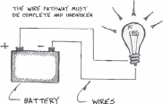
A COMPLETED CIRCUIT
There are two basic kinds of circuits, series and parallel. Series circuits are not often used in lighting, other than in control equipment such as a light board. In a series circuit, loads are connected together so that current must flow through each load in order to get to the next one. A load is a device that does work; for example a light bulb, or a toaster.
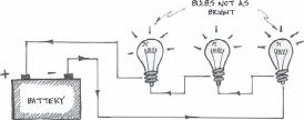
A SERIES CIRCUIT
There are some major drawbacks to a series circuit. First of all, if one of the loads is removed (such as a light bulb burning out), the circuit will be broken, and no more current will flow through it. In the olden days when I was a lad, it was common practice to wire Christmas tree lights together in a series circuit in order to lessen the amount of copper wire used. But it was so annoying to try and find one burned out bulb among so many that manufacturers gave up on the idea years ago. Another problem with the series circuit is that the amount of voltage present to any one load is decreased each time an additional load is placed on the line.
Electricity is formed by pushing electrons through a conductor. Voltage is a way of expressing how much pressure is being used to push the electrons forward. Lamps in a series circuit will never reach their full output unless they have been specially engineered to work on a lowered voltage. One type of specialty lamp fitting this description (other than those Christmas tree lights) is the aircraft landing light, or ACL. In the entertainment business they are used to emit a thin shaft of light on stage, but are really manufactured to use on airplanes. ACL's are designed to operate at 28 volts, which is apparently a standard aircraft voltage. To use them with a normal earth-bound voltage of 110v, it is necessary to gang four of these lamps into a series circuit so that the voltage reaching each one is only one fourth of the available 110v, or 27.5v. The concept of voltage is not terribly precise, and the difference of one half of one volt is not very important. Voltage must pass through all four loads in order to form a completed circuit.
This “sharing” of voltage in a series circuit can be better understood if you take some voltage measurements. In the llustration with four loads in series, the voltage flowing through all four loads is equal to the rounded-off supply voltage of 100v. The voltage potential across one load is one-fourth of the supply voltage, or 25 volts. Across two loads is 50 volts, and across three is 75 volts. If the voltage supplied to a light bulb is less than the lamp was designed for, the bulb will be dimmer than normal, so unless you have low voltage lamps, bulbs in series usually emit a reddish glow. Dimmers use this same principle when they reduce voltage to a light causing the bulb to be less bright.
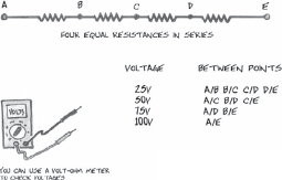
DIVING VOLTAGES IN A SERIES CIRCUIT
Electricity arriving from outside lines often fluctuates by several volts, depending on local conditions. The stated voltage of 110v is nominal, meaning that it is just an amount used as a name. Many times voltage is listed as 117V, and if you check voltage with a meter at a wall outlet you will find that it is very often in the 120- to-125 volt range.
Parallel circuits are much more commonly found in stage lighting than series circuits are. In this arrangement, power flows directly from its source to each load. The wiring used as delivery system may carry power to several lamps along the same two wires, but in no case will electricity flow through one load to get to another one. Hence the on/off status of any one particular lamp will not affect the status of the others, and since each lamp has its own direct source of power, the amount of voltage reaching each lamp will remain constant without regard to any of the other lamps.

VARIATIONS ON PARALLEL CIRCUIT
There are two basic types of electric current, direct (DC) and alternating (AC). These two types are defined by the way each one causes electrons to move through a conductor. In direct current (DC) electrons move in one direction only, from a source of surplus electrons known as the negative terminal (-), toward a collection point known as the positive terminal (+). A terminal is an ending point for a circuit. You can find the plus and minus signs on any battery next to its terminals.

IN DIRECT CURRENT (DC) ELECTRONS MOVE IN ONE DIRECTION ONLY
A power source like a battery provides a potential for electrons to move. Batteries use a chemical reaction to force electrons to move through the circuit. A car battery uses lead and hydrochloric acid to do that. It is very toxic and messy. Dry cell batteries use solids like carbon and zinc, which are much more stable and user friendly. Once the chemicals in a battery have been exhausted, it produces no more electrical charge. It is very common for electronic devices to use a power supply to convert AC power from a wall plug into DC power. That lowers your dependence on expensive batteries for appliances like jam boxes.
Direct current is not often used for lighting purposes except for very special arc-type lamps that require DC to operate. These are found mostly on followspots or large movie lights, most notably xenon or HMI lamps.
Any type of ordinary filament bulb will operate with either direct or alternating current with no problem, but electric motors are wired for one or the other. The speed of DC motors can be adjusted by varying the voltage supplied to them, much like varying the voltage will cause a light to vary in brightness. DC motors are used for equipment like gobo rotators and color changers because their speed is so easily controlled. Alternating current motors will burn out if you try reducing their voltage. That is why you should never connect an AC motor to a dimmer. AC motor speed can be controlled by altering the frequency of the current, but that is a much different process.

ALTERNATING CURRENT
AC HAS A HOT AND A NEUTRAL RATHER THAN A PLUS AND MINUS LIKE IN DIRECT CURRENT
Alternating current is much more commonly available because it was long ago adopted as the standard method. It is easier to transmit and requires smaller and less expensive wires. It is the type of current that is supplied to most homes and businesses. AC differs from DC in that its electrons move through the conducting wire in two opposite directions following a regularly scheduled pattern. There is a constant ebb and flow from the source of power, with electrons first being forced down the wire and then being allowed to lapse back toward the source. The speed at which this change of direction occurs is given in cycles or Hertz (Hz). Sixty cycles per second is standard in North America. The inscription 110VAC 60Hz on an electrical appliance indicates that it requires 110 volts of alternating current operating at 60 cycles per second. If you look, you will find this value on most of your household appliances, at least the ones that get plugged into the wall. Other countries use different values, and equipment is not usually interchangeable. A television set made for the European market will not work in the States without a special adapter, and vice versa.
Rather than having a positive and a negative terminal like a direct current battery, AC is said to have a hot and a neutral. The “hot” is the wire that is used to push electrons through the circuit. The word hot is indicative of the fact that this conductor is energized. The neutral is the wire that provides a resting place for electrons to go when they are not being used. Even though the neutral does not carry any usable electrons, it must be in place for the circuit to operate. When wiring electrical devices, it is important to make sure that the hot and neutral wires are attached to the proper terminals.
Alternating current is produced at a power station where some other form of energy, such as heat from fossil fuels or the inertia of falling water, is used to turn a generator. Rotating magnetic fields inside the generator induce electron flow that is cyclical in nature. As the generator rotates, wire coils pass in and out of magnetic fields. When a coil of wire moves through a magnetic field an electric current is induced in the wire. The speed and direction that the coil of wire takes in its passage through a magnetic field causes the current to become stronger and/or weaker.

AS THE COIL OF WIRE POTATES BETWEEN TWO MAGNETS, A VOLTAGE IS INDUCED. ELECTRONS FLOW FIRST IN ONE DIRECTION, AND THEN IN THE OTHER
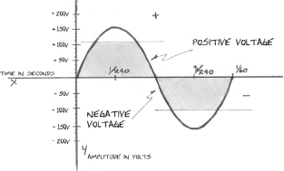
When the wire is passing at a right angle to the lines of magnetic force, the greatest current is induced. When passing parallel to the lines of magnetic force, no current is induced. When the coil of wire rotates halfway around the generator its polarity is reversed, and the current flows in the opposite direction. As a result, the current produced by an AC generator follows a pattern of strength and polarity demonstrated graphically by a sine wave. Over a period of time, the strength of the current becomes stronger to a certain point, then weaker down to zero. It reverses direction, becoming stronger in a negative direction to a certain point, and then returns to a zero point. One complete sine wave represents one complete cycle or Hertz.
ONE CYCLE OF ALTERNATING CURENT
THE USEFUL VOLTAGE THAT IS APPLIED TO THE LOAD IS THE AVERAGE VOLTAGE. THE RMS AVERAGE VOLTAGE IS INDICATED BY THE SHADED-IN AREA. THE ACTUAL PEAK VOLTAGE IS MUCH HIGHER.
VOLTAGE TRAVELS ONE DIRECTION WHEN THE CURVE IS IN THE POSITIVE QUADRANT. AND THE OPPOSITE DIRCTION WHEN THE CURVE IS IN THE NEGATIVE QUADRANT
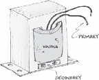
Power coming into a large facility runs at a very high voltage because that is the most effective method of transmission. Electricity at a very high voltage can pass through wires more efficiently. A transformer is used to transform, reduce, or “step down,” the high voltage to a more user-friendly voltage, which is generally 110 volts. Transformers for residential use are the large gray round things that are seen at the tops of telephone poles. They are much bigger than they look from the ground. Most commercial transformers are large square metal boxes with “Danger High Voltage” written on the side. Please trust the manufacturer that there are no user serviceable parts inside and stay away. Small transformers are used inside all sorts of things to provide a low voltage power supply. Six to 12 volt transformers that are used for doorbells are quite easily found at any hardware store. If you want to experiment with transformers, this is the type to use.
Basic transformers use two coils of wire to a change voltage. When electricity passes through a coil of wire it produces a magnetic field. Also, as discussed earlier, a magnetic field can be used to induce an electric current in a coil of wire. When a DC current is used, either the coil of wire or the magnet must be moving in order to induce that current flow. But if an Alternating Current is used, the magnetic field from the primary coil of wire is constantly expanding and contracting in time with the voltage changes that are occurring. This movement of the field itself is enough to induce a current in the secondary coil of wire. The proportion of the voltage in the primary coil to the voltage in the secondary coil is mostly a function of the number of turns of wire in each of the coils.
LOW VOLTAGE POWER TRANSFORMER
Power transformers are used to “step up” and “step down” voltages. A higher voltage is more dangerous than a low voltage. Electric current can jump across an open-air gap a distance of about one inch for every ten thousand volts. It is possible to be killed by a high voltage source without ever having touched any of the conducting surfaces. Lightning contains billions of volts, allowing its spark to jump across vast distances. Water, or more correctly the ions in it, make it much easier for electrons to flow. This is why you should be especially careful around electricity in wet areas.

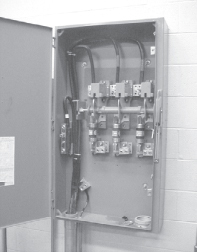
DISCONNECT BOX
You may often find alternating current that uses more than one hot conductor. In a theatre situation each of the hot wires carries its own separate 110v supply of power. A distribution panel that houses two hots and one neutral will therefore have a capacity of 220v when both of the hot “legs” are taken into consideration. This is the type of installation that is found in most homes. Some electrical devices, such as stoves, air conditioners, and clothes dryers, are designed to operate using both of the hot legs and are said to require a 220-volt line. Hence they have three conductors, two hots and a neutral. Smaller dimming systems are also commonly wired to use 220 volts. For stage use, it is not intended that any one lamp will be fed the entire 220v but rather that some of the lamps will be fed by one of the 110v legs, and others will be powered by the second one. The power will have been split up by the dimming system. In any case, there is no single potential that equals 220 volts.
When more electricity is required, three-phase power may be used. Three-phase has three separate hots and one common neutral. The name is derived from the timing sequence that is used for the various hot legs. For each hot in a three-phase hookup, the 60-cycle ebb and flow of electrons occurs at a slightly different timing schedule, and hence there are three distinct and separate phases. This is done in order to more effectively create and transmit the electricity. Some large motors are specifically wired to operate on three-phase because it is more efficient for them to do so. In reality, the timing of the phases will have little or no effect on lighting equipment.
DISCONNECT FOR 3-PAHASE POWER
NOTE THE 3 HOT LEGS WITH FUSES WHITE TAPE ON NEUTRAL BUSS AT LEFT GROUND CONNECTION AT THE BOTTOM

THE AC GENERATOR CONTAINS A NUMBER OF COILS OF WIRE. IT USES THE TO CREATE THERR SEPARATE CURRENTS EACH CURRENT FLOWS AT SLIGHTLY DIFFERENT TIME, OR PHASE. ALL THREE HOT PHASES CAN USE THE SAME NAUTRAL.
Lightbulbs have a small wire or filament inside them that is heated to create light. At a certain temperature, the filament becomes “incandescent,” and energy that was in the form of electricity is transformed into light energy. The wire filament becomes hot because it is too small for so many electrons to pass through easily. When there is too much electricity flowing through a wire, the conductor itself obstructs the passage of electrons. The extent of that obstruction is known as the resistance of the conductor. Resistance is one of the values used in the mathematical assessment of electronic circuits. It is present in any practical device used to conduct electricity, and any conductor will heat up when there is too much current running through it.
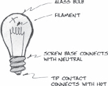
PARTS OF A LIGHTBULB
Resistance occurs in both AC circuits and in DC circuits. Since incandescent lightbulbs operate purely on the principle of resistance, it makes no difference at all whether the power supplied is AC or DC.
Any difference in the change or direction of the electron flow happens so quickly that it is not possible to see its affects. Even though electrons stop moving for the briefest of moments when the change in direction occurs, the lamp filament does not cool fast enough to record it. Sometimes though, the alternation of the current will cause the filament of a lightbulb to vibrate or rattle and this vibration can be heard as a buzzing noise. It is sometimes referred to as a “60 cycle hum.” Hum is more noticeable in a lamp with a large filament. You can easily hear it coming from many streetlights.
Sixty-cycle hum can be a serious problem for sound equipment. Low voltage lines such as microphone cables should be kept as far as possible from lighting cables, especially those carrying a large amount of current. Care should be taken in coiling the wire used to feed dimmer racks. Feeder cable typically carries a very high current, and coiling it in a circle can cause a large amount of induction such as is found in a transformer. This induction can cause a variety of problems for other electrical circuits backstage, and can even influence the power delivered to the dimmer rack itself. It is a better practice to “figure 8” the cable instead. This will prevent harmful induction from occurring.

STRAIGHT COIL CREATES INDUCTANCE

FIGURE 8 FEEDER CABLE TO AVOID EXCESSIVE INDUCATANCE
A color coding system is used to differentiate between the various conductors that are used for hot, neutral, and ground wires. The neutral is always white, colored with either paint, tape, or by the insulating rubber itself. If there is only one hot it will be black. If there are two hot legs the second will be red, and in three-phase the third will be blue. This practice is standard in North America. Ground wires are always green. Grounding an electrical device is a matter of safety and should not be taken lightly. Serious electrical shocks can cause severe burns, and if the electron flow passes through vital organs, death can easily result.
Electricity follows along a path of least resistance. Ground wires are used to provide a safe and easy pathway for electrons that have been misdirected due to some mechanical malfunction. Without a ground, your body may in effect become the path of least resistance should you inadvertently come into contact with a hot wire or some piece of metal that has come into contact with that wire. A copper ground wire is a better conductor than the human body, and the current will take that route if it is available.
A mishap with sparks and misdirected current is generally referred to as a short circuit, or short, meaning that the circuit pathway being taken by the electricity has been shortened. The current takes a new pathway and the device will malfunction. Most likely a fuse or circuit breaker will blow.
A related, but altogether different wiring problem, is that of a loose connection leading to an open circuit. Here the circuit path is broken, but no new pathway is found. This can often occur when a wire has come loose inside a connector or lighting instrument, or when a wire has been bent one too many times and breaks. If this happens inside the wire's insulation it may not be apparent from a visual inspection. Generally, the device will just not switch on. Sometimes a loose connection will result in the electricity arcing, in that electrons will jump over a small air gap in order to reach their normal pathway, much like the spark plug in a car. This may cause a light to flicker on and off. Arcing can create tremendous heat and can easily lead to a fire. It can be diagnosed by noting melted plastic, black scorch marks, or pitting of metal surfaces. The methods of troubleshooting short circuits and/or loose connections are different, and it helps to be able to distinguish between the two problems. Most commonly, a loose connection is known for failing so that the device does not work at all, or is intermittent. A short circuit will almost always trigger the circuit protection.
SMALL FUSE TYPES
Fuses and/or circuit breakers are intended to protect an electrical system against a flow of electrons which is too much for it to handle. This can happen when a short allows all available electricity to flow through a system like a dam bursting. Overloading is a slower and more problematic cause. Virtually all electrical devices are rated at a certain number of amps. The ampere rating is an indication of the amount of electricity that can safely flow through the device. Sometimes too great a load may be placed on a wiring or dimming system. This is known as an overload. Many times it is the result of too many lights being plugged into one circuit or dimmer. When too great an electron flow passes through a conductor, resistance to this flow will cause the conductor to heat up. Too much heat can cause insulation to melt, and fires to occur.
Resistance can be put to a good use in circuit protection devices. Fuses contain a strip of metal that has been carefully chosen to be of just the right size to heat up, melt, and break the circuit when a predetermined load limit has been reached. Fuses can provide this protection only one time, because after the metal strip has been melted, it cannot be repaired. Fuses should be discarded after they have blown. Jumping across a fuseholder with wire or any other piece of metal creates an extremely hazardous situation because it removes the protective action and can allow wires to overheat to the melting point.

BREAKER PANEL
Another type of circuit protection is the circuit breaker. Breakers use either electromagnets or bimetal strips to stop electron flow. In either type of breaker, an excess of current causes a spring-loaded switch to trip within the breaker, and current is stopped. This switch should be reset only after the cause of the overload has been found and corrected.

TYPICAL CIRCUIT BREAKER
MEASURING ELECTRICITY
The three basic units for measuring electricity are volts, watts, and amps. It is important to understand the theoretical relationship between them in order to understand how electricity can be used safely. Oftentimes mentioning these three words in the same breath can cause a student's eyes to glaze over, but this need not necessarily be the case. A practical understanding of these three concepts is easily reached when they are viewed in a logical manner.
As shown earlier, a change in voltage causes a change in the brightness of a lightbulb. This is how dimmers work, by varying the amount of voltage supplied to a lamp. Although dimmers may alter voltage in one of several ways, it is a reduction in the voltage pressure that causes the light to dim. Voltage is a measurement of the pressure of the current that is passing through a wire. It is often compared with water pressure, and there are many similarities between the two. Imagine that you need to water the lawn. You lay out a hose that is a conductor for the water just like a wire is a conductor for electricity. A sprinkler can be likened to a lightbulb, or any other electrical device that does work. When you crack open the faucet a small amount, the sprinkler will have a bit of water spurt out, but it will not go far, and if the sprinkler is a type that rotates, it will barely turn. Notice that as you turn the handle and increase the water pressure that the sprinkler rotates faster and faster. This is much the same as increasing the voltage to a light bulb and having it get brighter and brighter.
Wattage is a measurement of how much power is actually consumed by an electrical load when it is performing its work. A lightbulb that puts out more light also consumes more power. A 100-watt bulb puts out more light than a 25-watt bulb, but it also uses more power. A larger sprinkler will spray water over a larger area, but it will use more water in the process.
It could be said that the wattage of any particular load is an indication of how much electricity is being transformed by that device into some other form of energy. Blow dryers create heat and moving air. Lamps create light and heat. A washing machine converts electricity into motion. If you look on the back of an electrical device, you will likely find a record of its power requirements. Anything with a plug should list 110VAC 60Hz, and also some indication of the power it will consume. Lightbulbs have a wattage rating and so do blow dryers and microwave ovens. Some devices have an amperage rating instead.
Amperage is a unit that describes how much current is flowing in a circuit, but it can also be used to express how much power is available to be used. We have all had the experience of plugging one too many things into an outlet and having the breaker that protects it trip and cut the power. If you were to look into the breaker panel at your home, you might see that the main breaker is rated at 200 amps. This means that there are 200 amps of electricity available to power all of the devices in your home.
If you were to turn on everything in the house, all the lights, stoves, dryers, open the refrigerator, and then go next door to borrow all of their reading lamps and blow dryers, bring them back, and plug them in too, you would most likely trip that main breaker. Of course you would have to divide the loads evenly among the individual breakers to prevent tripping them before the main breaker. As you will recall, circuit breakers are there to protect the wiring from overheating. The amperage rating of different appliances is a reflection of how much electricity will pass through them when they are in operation. The amperage rating of a breaker tells how much current can pass through it before it trips.
So what is the relationship between watts, volts, and amps? George Simon Ohm discovered that there is a mathematical relationship between power in watts, current flow in amperes, electric potential in volts, and resistance in ohms. All of these units are named for scientists who made important discoveries.
Ohm's law states that power (watts) is equal to current (amps) times voltage (volts), and further, that voltage is equal to the current times the resistance (Ohms). The letters used to represent these measurements are:
P = power in watts
I = current in amps
E = voltage in volts
Ω= resistance in ohms
The Greek letter omega is the symbol for ohms.
The relationship between power, current, and voltage is often called the “pie” formula and it is written as P = IE. That makes it easy to remember. The second formula involving resistance is I R = E. The pie formula is much more commonly used in stage work.
P = IE
Power Formula
A very practical application of the P=IE formula can be found in calculating how many lights of a certain wattage can be used on a circuit with a breaker of a known capacity, when that capacity is expressed as an amperage rating. In practical applications, voltage is usually assumed to be a constant 120 volts. Although you already know that is not really the case, and especially not when dimmers are used to vary the voltage. It must be assumed for safety reasons however, that any dimmer will at some point reach a value of 100% and develop its entire 120-volt output.
If you wish to connect two 500-watt lamps to one dimmer, the amperage required to power them with 120 volts can be calculated mathematically. First add the total number of watts, 2 x 500 watts = 1,000 watts, so that is the total wattage on the circuit. The voltage value is a constant at 120 volts. These numbers may now be plugged into the P=IE formula, and expressed as 1,000 = I x 120. The unknown is I, the number of amps required. The problem can be transposed to I = 1,000/120. Dividing 1,000 by 120 results in a figure of approximately 8.3, to the nearest tenth, which is certainly close enough in lighting work. The most common amperage rating for small dimmers is 20 amps. As 8.3 is smaller than 20, it is easy to see that the two 500 watt lamps will easily fit into this dimmer. Of course you should inspect the actual dimmer system you are using to discover the exact amperage rating of the dimmers in it.
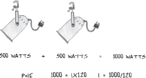
CURRENT EQUALS 8.3 AMPS
There are a couple of shortcuts that may prove useful. Using the PIE formula, you can also describe a 20 amp dimmer as being a 2,400 watt dimmer, and 30 amps will provide a 3,600 watt power supply. By using this method it is only necessary to add the wattages of the various loads and compare this total to the capacity of the dimmer itself. For example 750 +750+ 750 = 2,250, which is less than 2,400 watts or 20 amps. 575+575+575+575= 2300.
You may have noticed a discrepancy where many devices use a voltage rating of 110 or 117 volts, while most dimmers consistently have a nameplate rating of 2.4kW. This is because theatrical lighting engineers use a nominal voltage figure of 120 volts to do the calculations. This amount is actually a much more practical figure. As previously discussed the voltage present in practical circuits is somewhat variable.
A second shortcut uses 100 volts as a constant when computing the number of amps required. This will do two things. Since 100 is smaller than 120, using it as the divisor will cause the answer you get for the number of amps to be a bit larger than the answer the 120 divisor would give you. This provides for a safety factor; 1,000 watts translates to 10 amps, and 1,500 to 15 amps. As should be apparent, this also permits the arithmetic to be simplified so that all that is really necessary is to move the decimal point two places to the left. In this way 1,000 becomes 10, 1,500 becomes 15, 2,000 becomes 20, and so forth. This is a good method for making rough estimates in your head. Of course it is not as accurate as the longer method.
Always keep in mind that although electricity has been a great boon to mankind, it can also be quite dangerous. When working with large amounts of current, do not go beyond your knowledge of the subject. Do not touch anything electrical (except the Energizer Bunny) unless you are absolutely certain of the hazards involved.
HOW DIMMERS WORK
There are three basic kinds of dimmers: resistance, autotransformer, and SCR. They each work in very different ways, but the end result is that each one reduces voltage to a given circuit as a means of dimming lighting. Auto-transformers and SCRs are used almost exclusively in lighting circuits. Many years ago, resistance dimmers were used for lighting, but it would be difficult to find one still in use at the present time. Even so, resistance dimmers are often used as volume controls on radios and other sound devices. They are also used on manual boards like a two-scene preset. In these applications they are only controlling a very small voltage that in turn controls something else. On a lighting board the “sliders” typically manipulate a 0- to 10-volt signal to operate a dimmer that actually controls current to the lights themselves.
A resistance dimmer is placed in series with the load. The resistance of the “potentiometer,” as they are often called, is variable according to the position of the knob or slider. When the resistance is high, most of the voltage in the circuit is expended across the “pot.” When the resistance is low, more voltage is applied across the intended load. The main drawback to resistance voltage control is that current is being consumed at all times, and this can be very wasteful at higher voltages. It is not so problematic at low voltages. Old resistance dimmers got very hot, because they converted all of the unneeded electrical energy into heat energy.
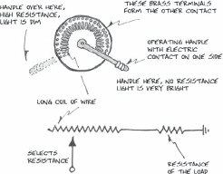
BECAUSE THE RESISTANCE OF THE DIMMER AND LIGHT ARE IN SERIES WITH ONE ANOTHER, ADDING RESISTANCE AT THE DIMMER DECREASES VOLTAGE AT THE LIGHT.
Auto-transformer dimmers use a variable transformer to alter voltage, and could more properly be called a variable transformer. (Some are.) Transformers use coils of wire to “transform” a voltage from high to low or vice versa. The length of the wire in the coil, and the proximity of the coils to one another determine the various voltages. In a standard power transformer, the coils have set values. In an autotransformer the two coils can be rotated into and out of, proximity to one another. Moving the coils back and forth varies the amount of voltage that is induced from one to the other. Dimmers of this type tend to be very heavy and difficult to operate physically because they contain huge coils of very heavy wire. They can only be controlled by mechanical power, such as a human arm or a motor. This makes them problematic for use with a computer light board, so auto-transformers now have a limited use in stage lighting. They are still used architecturally in some specific ways, and are a good example of how transformers work.
SCR and other types of electronic dimmers are very common in stage lighting. They can be controlled by a digital signal from a computer, and this opens the door for much more complicated lighting design schemes for the designer. An SCR or Silicon Controlled Rectifier is a type of semiconductor transistor that can turn a circuit on and off. Electronic dimmers are actually very fast switching devices. They switch power on and off at a very fast rate, so fast that it is not apparent to the human eye. They are used to “chop” up the alternating sine curve of AC power into small chunks that can be either on or off. AC voltage is commonly expressed as an average amount since it is constantly changing anyway. The Root Mean Square (RMS) method is used to take this average.

GRAY AREA REPRESENT VOLTAGE TURNED ON
The actual peak voltage of an alternating current sine wave is much higher than the average voltage. If the sine curve is chopped up so that voltage is present inside parts of the curve, but absent from other parts, then the resulting average will be lower still. When the voltage output is tested with a suitable meter, the RMS average voltage is a function of how much of the sine curve has been removed by switching the circuit on and off. The voltage can be so low as to keep the light bulb filament from incandescing, and no light will come out of it. Or the switching rate can be adjusted so that all of the voltage coming into the dimmer is applied to the light.
LIGHTING INSTRUMENTS
There are many different types of theatrical lights, but the few discussed here are by far the most commonly used. The largest manufacturers, such as Altman, Strand Century, ETC, and Major, have somewhat different engineering approaches to the manufacture of lighting equipment, but the actual workings of the lights themselves are more or less the same. The most often used theatrical lights are the ellipsoidal, Fresnel, PAR light, and strip or border light. In recent years moving fixture lights have become much more available and widely used, especially in the concert industry.
Virtually all theatres use some form of c-clamp to attach lights to a pipe such as a boom or an electric. This is a specialized clamp that is able to grasp a round pipe easily. At the bottom of the c-clamp is a ½" bolt that connects the clamp to the yoke. It also allows the light to move from side to side. Most of the time the yoke is a piece of flat steel that is bent into a U shape. It curves around the sides of the body of the light and is attached on either side with bolts or handles. They allow the light to move up and down.
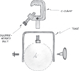
MOUNTING HARDWARE
If the light is to be secured to a truss or tower, then the yoke is usually bolted straight to that frame with no clamp. Some tour lights are bolted on to six or eight-foot sections of unistrut so that they are hung as a group in order to speed up hanging. The unistrut is fitted with two clamps, one at either end. Clancy clamps are used instead of normal c-clamps. Clancy manufactures a quick attachment clamp that is spring loaded with a retaining nut that can be closed very quickly by hand and requires no wrench. Strip lights have a half yoke and a c-clamp at either end.
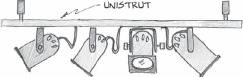
PAR CANS HUNG ON UNISTRUT
On the front of a light is a slot where gel frames may be fitted. On the back is a power cord, or pigtail, that is used to plug the light into a circuit. Most lights have either handles or bolts (or both) on the side, which are used to secure the light from tilting up and down.
FRESNEL
The Fresnel is perhaps the oldest kind of still existing lighting instrument and has been around longer than any of the others listed here. It was named for the man who invented the type of lens they use. August Fresnel knew that light passing through a dense medium such as glass is slowed, and the trajectory of the beam is altered.

LIGHT REFRACTION THRU A PLANO-CONVEX LENS
Glass lenses that are thicker in the middle tend to concentrate light passing through them into a more coherent beam. This type of lens is known as a plano-convex lens when it is flat on one side and curved outward on the other. The problem that Fresnel faced was that these lenses were very thick and often cracked from the heat of the light source.
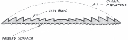
Monsieur Fresnel discovered that the curvature of the convex side could be stepped back as long as the curvature on the surface remained constant. This resulted in a much thinner lens, which is helpful in preventing cracking due to heat expansion and contraction. In reality, the stepped concept doesn't work all that great because of all the inaccuracies that creep in during the manufacturing process, but the optics in a Fresnel don't need to be too terribly precise. In fact, most of the lenses are “pebbled” with a rough texture on the back so that the light emitted is more diffuse. This helps to cover up any irregularities in the beam of light. Fresnel was actually working on lighthouse fixtures that are much larger and more powerful than your typical theatrical unit. Hence the heat build-up factor was much more important.
FRESNEL LENS
Fresnels use a reflector that is shaped like a segment of a sphere to bounce light vaguely back in the direction of the lens. Both the lamp and the reflector are fastened to a “sled” that can be moved back and forth, toward or away from the lens. The closer the sled is to the lens, the more spread out the beam pattern will be. This position is referred to as flood. (Just remember, forward = flood.) When the sled is moved away from the lens, the beam output is sharpened into a position known as spot. There are an infinite number of stops in between the two extremes.

SLED MOVES BACK AND FORTH
Regardless of the number of degrees of beam spread, the light output of a Fresnel is always somewhat diffuse, with a bright or “hot” spot in the center, and a gradual lessening of intensity toward the edge of the beam. A common accessory used in limiting the beam spread of a Fresnel is a set of “barn doors.” Essentially, barn doors are hinged metal flaps on a mounting plate that can be fitted into the gel frame at the front of the light. They are especially popular in a television studio. By adjusting the angle of the flaps it is possible to mask the leakage of unwanted ambient light that tends to angle obliquely outward from the imperfect Fresnel lens. A “top hat” is a rounded masking device based on the same principle.

BARN DOORS

TOP HAT
The most common sizes of Fresnels are those that are six or eight-inches in diameter. Larger Fresnels are common in television and film. On occasion, Fresnels are called by their lamp wattages, such as a 2 or 5K (2,000watt or 5,000watt).
It is interesting to note that ETC does not currently offer a Fresnel lighting instrument in its family of theatre lights. Apparently ETC feels that the Source Four “Parnel” style lamp can provide the same functions as a Fresnel without the complexity involved in offering another line of fixtures. The trusty old Fresnel may be on its way out as a theatre light.
ELLIPSOIDAL REFLECTOR SPOTLIGHT
Sometimes ellipsoidals are called Lekos, because they were developed by two people named Lee and Cook. (That was in the 50s, hence the “Krazy K”.) Their company used that as a trade name. Ellipsoidals are the workhorse units of the theatre and account for a majority of the fixtures used. Their main advantage lies in the type of optics used and consequently their ability to shape the light beam they produce. An ellipsoidal can be used in more subtle ways than other kinds of lights because it can be more finely controlled. They are used extensively in theatre because theatre lighting is a more subtle art form than TV or concert lighting. TV lighting tends to center around high wattage Fresnels, and concerts (where the PAR once was king) now use moving fixture lights almost exclusively.

LIGHT RAY IS REFLECTED AT THE SAME ANGLE IT STRIKES THE MIRROR
As the longer name implies, a Leko utilizes an elliptically shaped reflector. A well known axiom about the reflection of light states that the angle of incidence is equal to the angle of reflection, meaning that a light ray will be reflected at the same but opposite angle at which it hit the reflector.
An elliptically shaped reflector puts this principle to good use. By definition, an ellipse has two focal points. If you extend a straight line from one focal point to the ellipse, and then back to the other focal point, the angle on either side of the two lines will be the same. If a lamp is placed at the first focal point, the reflector will send all the light rays emanating from it back to the second focal point. This means that most of the light from the lamp is concentrated at the second focal point. Of course there are some light rays that never hit the reflector at all, because the system has imperfections. Light that is uncoordinated is call ambient light, and it tends to spill out in the most unwelcome places.
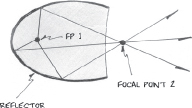
HOW THE ELLIPTICAL REFLECTOR WORKS
Still, this method of coordinating light rays is very efficient. Once the light has been concentrated at the second focal point, the rays cross over themselves and are then further concentrated by a pair of plano-convex lenses. Plano-convex lenses focus light into a tighter pattern as described earlier.
This system results in a very coherent light beam that is quite uniform in intensity from one side to the other. A modern ellipsoidal uses a double set of thinner plano-convex lens rather than one thick one. By varying the placement of the lenses, the output may be brought into a sharp focus. These qualities of high intensity, a coherent beam, and adjustable focus account for the most useful feature of an ellipsoidal, its ability to shape the light beam.
It is possible to mask part of the light beam when it is in the space between the two focal points and then to project the resulting shape onto the stage itself. The area of an ellipsoidal where shaping of the beam occurs is known as the gate. The shaping operation occurs before the light rays have merged and crossed over themselves at the second focal point. Consequently, any masking that takes place will appear as reversed when the beam reaches the stage. The optics in an ellipsoidal are quite similar to those in a slide projector.

PARTS OF AN ELLIPSOIDAL
Two different approaches may be taken to masking the beam. The most common is to use shutters, four thin pieces of metal that slide in and out of the gate and are a permanent part of the instrument. Shutters can make the beam of light into a semicircle, or a square, or, by angling the shutters, a triangle. Shutters are quite useful in shaping the light to fit a specific object such as a window or a door.
SHUTTER
The second type of masking creates actual patterns of light with very thin stainless steel sheets that have been chemically etched into complex shapes such as leaf patterns, clouds, starbursts, or windowpanes. Hundreds of different types are available. These patterns are also known as gobos or templates. Patterns of this type are put into holders and inserted into a slot next to the shutters.
GOBO HOLDER WITH A BREAK-UP PATTERN IN IT
In order to project properly, patterns must be inserted upside down and backward, similar to slides in a slide projector. Shutters work in the same way, so that the left shutter affects the right side of the beam, the bottom the top of the beam, and so forth. It is not possible to shape the output with barn doors, top hats, or any other equipment that is fitted into the gel frame holder, although these are sometimes used to mask away ambient light created by imperfections in the instrument.
The light coming out of an ellipsoidal increases at a given angle, and the farther away the light is from the stage the more spread out its pool of light will be. Theatres have specific lighting positions that are at different distances away from the “target.” It is important to have lights with different angles of beam spread so that the various distances can be accommodated. Otherwise, a great deal of efficiency would be lost from shuttering away too much of the light pool on some occasions, while at other times the shaft of light from the ellipsoidal might be too small to cover the intended part of the stage.
FOCLA LENGTH AND BEAM ANGLE
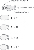
Traditionally, ellipsoidals were named and rated according to two factors, the diameter of the lens and the distance between the two focal points. A newer system gives a degree angle spread for a specific light. It is the designer's responsibility to determine which angles are appropriate, but it is important to know how the choices are made so that you can understand the logic behind them.
There are several ways to describe the size and use of ellipsoidals. The most popular lens diameter is six inches, but other sizes are available. Generally speaking, larger diameter lenses enable a bigger fixture that can hold a higher wattage lamp. Of course, the larger the lighting instrument is, the more difficult it is to hang and focus. Six-inch diameter lights have proven to be a comfortable size.
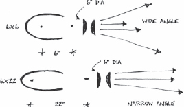
The distance between the focal points in a light determines the amount of spread that occurs in the beam angle. The farther apart the two focal points are, the narrower the angle will be. Focal lengths for traditional lights in the six-inch-diameter size range from six inches to twenty-two inches. The beam spread of a 6x6 is much wider than the beam output of a 6x22, and as a result, the pool of light emitted by the 6x6 (at the same distance) will cover more area on the stage than the 22 will. Generally, a 6x6 is intended to be used from a hanging position that is very close to the lighting area, whereas 6x22s are usually hung from a far distance. As you can see, the lens diameter is always written first, and the focal point spread second. The most common sizes are 6x6, 6x9, 6x12, and 6x22.
There is a newer system that uses a different approach in describing and creating the beam angle spread. Some manufacturers’ fixtures are designed so that they all use the same housing, and different lens arrangements are used to produce the different beam angle spreads. These range from a very narrow angle of 5 degrees to a wide angle of 50 degrees. It is possible to purchase extra lenses so that one body can produce different angles by switching lens tubes. It is also possible to rotate the shutter section, making it easier to angle the shutters to an odd position.
PARABOLIC ALUMINIZED REFLECTOR SPOT
PAR cans are essentially round car headlights that have been manufactured to operate at 110 volts, rather than at the standard automobile voltage of 12v. The fixtures themselves are very simple, lightweight, and inexpensive because all of the optics have been built into the lamp itself. As a consequence, PAR lamps tend to be somewhat expensive. It is the nature of a parabolic reflector that it reflects straight outward whatever light rays strike it. So the lens is really meant to slightly blur the light beam into a more homogenous pool.
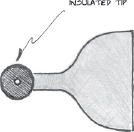
PAR cans were the standard rock-and-roll light for many years because they are so lightweight and durable, and because rock shows do not require a great deal of precision in focusing. The beam that comes from a “can” is similar to that generated by a Fresnel, except that it is oval in shape and the instrument does not allow for changing from spot to flood. Instead, a variety of lamps may be used. They range in angle from wide to medium to narrow to very narrow. Even narrower ACL lamps may be used, but these require a different voltage as described earlier. The obvious disadvantage to this system is that the entire lamp must be changed rather than simply cranking from spot to flood.

PAR LAMP
It is possible to rotate the lamp within its housing in order to change the orientation of the oval beam shape from vertical through horizontal, in accordance with how the light can best cover its intended area.
PAR cans come in either black steel or shiny aluminum versions. The gel frame holder has a spring-loaded clip at the top to prevent the frame from sliding out during transport. Cans come in two main sizes, the 64 and the 56, with a few oddballs in the 38 category. PAR 64s are far and away the most common. The peculiar sizes refer to the diameter of the lamp given in one-eighths of an inch. (64=8")
A newer type of PAR is very different from the traditional light. It has a standard reflector and lamp, and the lens is changed to alter the beam angle of the light. A ring known as the “bottle” is rotated to change the direction of the oval, and that oval is much less pronounced than in a regular PAR. These fixtures are much more expensive than a regular PAR can, but they have the advantage of using a much cheaper lamp that just happens to be the same lamp as is used in many other lights. A cheaper lamp really starts to make sense the longer you use the fixture.
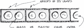
STRIP LIGHTS
Strip lights are also known as border lights and on occasion are referred to as x-rays by a few elderly stagehands. As the name implies, they are lamps that are manufactured in strips, where a number of lamps are ganged together in a parallel circuit. The typical unit has two or four lamps in each circuit, depending mostly on the size and/or wattage of the lamps. Mini Strips have a large number of very small lamps placed in groups of two. The standard hookup uses a staggered approach so that the lamps are lit in this fashion: ABCDABCDABCD. The alternation provides for a more even spread of light from each of the groups.
By plugging several strip light units together end to end, it is possible to create a swath of light across the entire stage, and/or as they are most commonly used, across a sky cyclorama. Strip lights allow you to have several different groups of evenly spaced lights that are independent of one another. By using different colors in each circuit, colors on the cyc can be mixed together. If red, green, and blue are used (the primary colors for lighting) a theoretically infinite color range may be achieved.

PARALLEL CIRCUITS IN A STRIP LIGHT
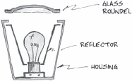
It is generally best to use one set of strip lights from above, and another one on the stage floor to achieve an equal distribution on the cyc. A scenic ground row is often used to mask the bottom strips. Confusingly, the bottom strips themselves are also referred to as a ground row, and that term can be used to describe either the lights or the scenery. Many theatres use strip lights as work lights for the stage. This is very common in older theatres as well as public school theatres. Lamp sizes and styles are quite varied, and strip lights are often described by their length, such as a six-foot or eight-foot strip. The standard old-style border lights use ordinary PS or A-shaped medium screw base lightbulbs, but newer types use high wattage quartz lamps. Round glass color filters, known as roundels, are often used on the older lights.
OLD-STYLE STRIPLIGHT
Strip light circuits are easy to overload because of the large number of individual lamps that are used. Care should be taken to determine the individual lamp wattage and multiply it by the total number of lamps in use. Compare this wattage rating with the dimmer capacity, or use the P=IE formula to convert to amps. One development in strip light technology is the Mini Strip, which uses tiny 12-volt lamps wired in series of ten (accounting for 120 volts). A three-circuit strip has thirty of these lamps in it. They are worth mentioning just to get one more insight into how a series circuit changes voltage. The advantage to this fixture is that it is very slim and will fit into tight spaces. Also, the sheer number of tiny lamps ensures a more even wash on a cyc. However, they can be a real pain when one of the lamps blows, and it is necessary to locate the offending bulb by the trial-and-error method.
Coming out with a new kind of lamp is a very expensive proposition for a lighting manufacturer. It would not be cost-effective to invent an entirely new lamp just to use in the Mini-Strip. It makes much more sense to design the fixture around very small low-voltage lamps developed for use in homes and businesses.
MINI-STRIP
MOVING FIXTURE LIGHTS
This heading covers a lot of territory, because there are many new types of moving fixture lights. This corner of the market is just beginning to really blossom as their cost has fallen. The generic name “moving fixture light” reflects the notion that the light itself can move under its own power. These lights can pan and tilt all on their own, but even more than that, most are able to change colors, change beam angle, and many can change and rotate gobos. Color changing is accomplished using a dichroic filter, a prismatic device that changes white light to different colors by tilting the angle of the filter to a pre-determined setting used for that color. Prismatic action selects the desired hue.
There are two main categories of moving fixture lights that are based on how they produce the motion. In the earliest fixture designs, the entire light was made to move. There is a large motorized yoke that allows the center part of the fixture to tilt up and down, while the yoke itself pans from side to side. Most cannot spin an entire 360 turn, but must stop and go back if necessary.
The other basic type are lights that use a mirror to move the light beam. All of the mechanics of the fixture are stationary except for a mirror that is angled to reflect the light beam in different directions. This type saves on the complexity of large moving parts. Curiously, these lights tend to be somewhat larger that the original type. Both varieties are still in full production.
The moving fixture concept was made viable because of the development of a complex control mechanism. Originally, it was necessary to use a computerized lighting control board designed specifically for these lights. They operate from a DMX (Digital MultipleXing) signal but require many different channels to control the various light functions of panning, tilting, color changing, etc. That was problematic to program on a standard lighting console. Newer theatre control boards accommodate the increased demands of moving fixture lights, although a board designed specifically for them has more options.
The concert lighting industry has been completely changed by the technological revolution of these new systems. How far they will go in legitimate theatres remains to be seen. It is hard to imagine how moving fixture lights could be used to improve a production of Uncle Vanya, but it is easy to see their value for Jesus Christ Superstar.
LIGHT PLOTS
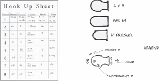
The designer should provide a light plot. It should be a scale representation of the theatre and its lighting positions, showing the lighting equipment types in their proper locations. Computer-Aided-Design (CAD) plots are often used. CAD programs come into their own in lighting design because they are really good at keeping track of all the numbers used for dimmers, channels, circuits, gel colors, and the like. It is also much easier to add and delete lights on the computer and then print out a new plot than it is to start over from scratch the old way. However, it should be noted that there were many very artistically satisfying lighting designs created in advance of CAD technology. The computer just makes the paperwork a lot easier.
The aesthetic quality of individual light plots tends to vary greatly, but there is a general consensus about the information that should be on the plot. If your designer shows up with some scribbles on the back of a paper bag, you have my permission to laugh and say “No way!” Of course, then you have to hang it anyhow.
The plot should include a legend, which is a guide to the meanings of various symbols for different types of lights and to the numbering system for gel color, circuit numbers, dimmer channel numbers, and instrument numbers. This is just like the legend used on a road map to indicate types of roads, hospitals, airports, etc. Front-of-house positions should be labeled, as well as the battens being used as electrics. Electrics should have an indication of their trim height.
STANDARD LAMP SYMBOLS

LEGEND
Some plots have marks on the battens at 18-inch centers. This is the most common spacing alternative for hanging instruments. Maintaining this spacing ensures adequate room to properly focus the lights. Using corresponding marks on the battens can make a light hang go really fast. If the design calls for lights to be too close together, focusing will become problematic somewhere down the road.

USING REGISTRATION MARKS TO AVOID MEASURING

LIGHTING MARKS ON A BATTEN
If no marks are shown, it is necessary to “scale off” the placement of lights using a scale rule. Half-inch scale is standard for theatrical drawings of all types, but ¼" is also quite common. Generally, if you can get the measurements correct to within a few inches this will be close enough. An ordinary tape measure can work well if the plot is in ½" scale. For that scale, one inch is two feet, an inch and one half is three feet, and so forth. Experienced designers tend to use a standard spacing, rather than making each space a different size. This speeds up the hang and leaves more time for focusing.
Hanging lights can be done very quickly if you organize the event before starting. Proper management is the key to success.
Research the plot to find gel colors, also the number and size that you will need of each one. Cut the gels and load them into the proper frames. Any sort of resident or university theatre will most likely have a filing cabinet with previously used gels stored in file folders. They are sorted according to the number each is assigned by the manufacturer. The colors have names too, but most everyone uses the numbers to specify. It is helpful to mark the color numbers with a china marker or a white lead pencil of some type. Do this right in the center of the gel, large enough to be easily read in the dark. The output of light and the quality of the color will not be noticeably affected, and readable labeling will make focusing much easier. Some purists will disagree with that, but the reduction in light output has never been apparent to me, so being a very practical and organized person, I always tend to want clear labels.

GEL FRAME HOLDER
Holes are provided so that brass office brads may be used to secure the gel in the holder. Some people use tape instead, but over a period of time the intense heat generated by the light will cause the tape either to fall off, or to become permanently bonded to the frame, depending on the type of tape used. Tape can also be a fire hazard. The manufacturers clearly intend for brads to be used.
This is also a good time to prepare any patterns or gobos that may be required, as well as to find barn doors and other accessories.
HANGING THE LIGHTS
Electrics are the most straightforward hanging positions because they are generally the same in all theatres. Front-of-house positions vary greatly from space to space. These instructions are meant for an electric but can be adapted somewhat for FOH positions.
Fly in the batten to be used as the first electric. In a perfect world, it is best to hang your electrics before loading in any scenery that would be in the way. Select the lighting equipment needed for this electric, and place the lights in their approximate positions on the floor beneath the batten. If both the plan and the batten are marked with 18" centers it is an easy matter to count the number of marks to determine the exact placement of an instrument. If you do not have this luxury, it will be necessary to measure as previously described. In any case, you should always begin from the center and work toward the two sides because designers may be somewhat lax about drawing battens to their proper scale length. Starting at the end often causes the lights to be hung off center. The center of the batten is a well defined location.

ALWAYS MEASURE FROM THE CENTER OF THE PIPE
If you must measure the placement of lights with a tape, it is helpful to determine all of the measurements on the plot first, and then mark all of the places on the batten at one time, using a piece of chalk to mark the hanging locations. Have someone hold the end of the measuring tape at center while you do this. The crew can hang the lights on your marks and finger tighten the C-clamp bolts. After all the lamps are hung, it is a good idea to double-check placement with the plot, as this is the last time when it will be easy to move a light. C-clamps are constructed so that they will not come off unless the bolt is very, very loose. Finger tightening will prevent the lamps from falling during the short time that you are hanging and double-checking. When it is time to tighten the clamps with a crescent wrench, it is only necessary to tighten the bolts enough so that they are tight enough to not vibrate loose. Over-tightening with a giant wrench will damage both the clamp and the batten. Having one person go along and tighten all of the bolts in order at one time is an efficient way of ensuring that none of them are left loose accidentally. If you are not sure, it is always best to go through and double check.
Rotate the lights so that they are pointed vaguely in the direction shown on the plot. Most lights have a “this side up” issue that becomes obvious when you look at the gel frame holder. Check to see that all the handles and bolts used in focusing are snug, but not overly tight. Make sure that all shutters are pulled out on all of the Lekos. Shutters are often completely closed when the fixture is in storage. In that position, they don't allow any light to escape and will turn a 1,000 watt ellipsoidal into a 1,000 watt heater. The shutters will soon warp out of shape to a point where they will need to be replaced.
Safety cables should be attached so that they go around the yoke of the light and also around the batten. This will keep the light from falling should someone have forgotten to tighten the C-clamp. You are now be ready to cable and circuit the electric.
If your theatre is equipped with plugging strips that are permanently attached to dedicated electric battens, this process is very easy. Simply plug the lights into the nearest circuit and record the number on the plot. Recording circuit numbers is essential so that a patching hook-up can be generated later on. A soft-patch in the dimmer board is used when the theatre has a dimmer-per-circuit system. If there is a patch panel to connect dimmers and circuits, the patch will be made there. In either case, you will need to know which dimmer or circuit is being used for which light.
The only concern with dedicated electrics is the fact that it limits the number of possible hanging positions. Drop boxes are much more difficult to work with, but they provide a high degree of flexibility. A drop box typically consists of a long piece of multicable (a large cable with many conductors) that ends with a box that contains a number of panel-mounted female connectors. The multicable extends downward from the grid, allowing the drop box to be moved around the stage. When lowering a drop box it is important to let the cable in directly over the batten so that the cable does not foul any of the surrounding battens. They will be needed for other work. Sometimes drop boxes are hung off to the side of the rigging system and are maneuvered with a pick line as shown in the chapter on theatres.

DROP BOX ON A BATTEN
A good method of attaching drop boxes to an electric is to use a C-clamp that has been bolted to the metal housing of the box. If this is not possible, be sure to use a stout line and a secure knot, because the box and cable are often surprisingly heavy.
You can determine the number of circuits needed, and hence the number of drop boxes, by counting the number of lights on the batten as described by the light plot. Sometimes the designer will know in advance that two or more lights will be ganged together into one dimmer and will show that on the plot. In this case it will not be necessary to provide an entirely different circuit for each one of these fixtures. The designer indicates ganged-together lights by drawing a line on the plot from one light to another, which is the normal way of indicating “two-fering” (two for one). A special twofer cable having one male plug connected with two female plugs is used for this purpose. Although it is the designer's responsibility to have determined in advance the proper power requirements dictated by connecting lamps together in this fashion, it is a good practice to double-check how much power will be required by the total number of lamps linked together by two-fering. This is especially true if two-fering becomes three-fering, or perhaps four-fering. Use the P=IE formula to do that. Some theatres use the branch-off, a device that allows three or even four lights to fit into one circuit.

Extension cords used to connect the pigtail of a lighting instrument with a drop box circuit are referred to as jumpers, because they “jump” power from one location to another. Jumpers consist of a single circuit with a male plug at one end and a female at the other. Hopefully it is not necessary to describe which plug is which sex. It should be noted that male plugs are never “live,” meaning that no electricity is supplied from them, but rather only to them. If this were not the case, electric shocks from the exposed prongs of the male plug would happen constantly. Female plugs are generally designed so that the conducting material is recessed back into the insulating material of the plug housing, and thus humans are shielded from the electricity. Only female connectors are a source of power.
Using jumpers to connect lights and circuits can be either very straightforward or a nightmare depending on how organized an approach you employ. Here is the method I have used to avoid cable snarls and mispatching.
Jumpers of varying lengths are needed to cover the distance from the fixture pigtails to circuit boxes. It is helpful to color code the different jumper lengths with vinyl electrical tape so that you can easily tell them apart. Then it is possible to tell at a glance which jumper is the proper one for the job. All cables should be fastened to the batten with tie line. Do not use tape or wrap the cable itself round the batten repeatedly. These two inferior methods are quite difficult to remove after the show is over, and the entertainment business is all about changing from one show to another.

Jumpers usually have a piece of tie line attached to keep them together when coiled and not in use. If you tie this piece of line a few inches from the female end, using a clove hitch so that it is permanently attached, it can also serve as the first tie used to secure the jumper to the batten. There are also some great little Velcro strips made for this purpose. Tie the female end near the C-clamp of the light to be connected. Tie it close enough so that there is enough slack in the pigtail for the instrument to pivot easily during focusing. Run the jumper along the floor and plug it into a circuit or dimmer. Record this number next to the light as it appears on the plot. Repeat this procedure until all of the lights have been plugged.
This is a good time to test the lights to make sure that all of the elements are in proper working condition (lights, jumpers, and drop box circuits). Patch each circuit into a load test, or run each dimmer to full one at a time. The exact method differs from system to system. Check each circuit one at a time and troubleshoot any problems as you go along. If there are individual circuits involved, it is best not to torture a dimmer by having it pop on at full repeatedly. Use a load test circuit or non-dim to do the testing. Non-dims are switches that operate through the lighting system to connect things like work lights and electric motors that will not function properly on less than 110 volts of electricity. With a dimmer per circuit system, you can just bring up the dimmers one at a time.
It is important to test your hang while it is on the ground and still relatively easy to troubleshoot. It is much easier to trade out or repair any faulty equipment before the batten is way up in the air. Make sure all of the shutters are pulled out and that safety cables are in place. Some designers like for the color to be put in now before the focus, and some like to do it after.
Once troubleshooting is over, and all the lamps are working, it is time to tie up the cables to the batten. Start at the end that is farthest from the drop boxes and use tie line to secure the cable. Put on a tie every four feet or so, and pick up the additional jumpers as you go along, tying them all at once using a bow knot. Thirty inches is a good length for tie lines because it will usually allow the line to be double wrapped around the cable. The two turns around the pipe makes it easier to get a tight bundle. If #4 black tie line is used, the ties can be recycled several times. When you reach the end where the drop box is, squish the excess cable against the batten and tie it on as neatly as possible. A bit of tidiness now will pay off when you focus, and will also help keep other flown pieces from snagging on the electric. Try to keep the rubber insulation of the jumpers away from the instrument housings, which get very hot during the show. The pigtail wires are usually OK, as they are manufactured with this in mind.
When the electric is ready to be flown out to its trim, use a small piece of gaffer's tape to secure the end of a 50- or 100-foot tape measure to the pipe before it goes up. Use the tape measure to determine when the batten has reached the proper trim height. Reel off the tape so that you can hold the exact length on the floor with your foot. When the slack is out of the tape you are at trim. Once the trim is set the tape measure can be yanked down. (Don't use too much gaff tape!)
Front-of-house positions are so varied that it is impractical to discuss how they may be hung or circuited, but the basic principles just covered should still apply.
When all of the lights have been plugged into various circuits, and a number identifies each of the circuits or dimmers, connections need to be made. In systems with a patch panel, circuits must be plugged into dimmers. Dimmer-per-circuit systems need to be soft patched. The default setting causes the dimmer numbers to equal the channel numbers. Assigning dimmers to specific channels makes it possible to have a rational order to the numbering system rather than the random order produced by hanging. Keep in mind that a dimmer is an actual piece of hardware. Channels are a method of renumbering dimmers so that they are easier to catagorize.

OLD STYLE PATCH BAY
The most common patch bay is the old plug or switchboard type. Male plugs at the ends of flexible cords hang down in front of a panel with sockets in it, much like an old-style telephone system (now only seen in old movies). There should be a list of numbers on the panel, which represent the dimmers that are available. Each dimmer number normally has several sockets next to it, so that you can plug more than one circuit into the same dimmer. Use the P=IE formula to determine that you are not asking too much of any one dimmer, and insert the male plugs into the sockets as required.

SLIDING CONTACT PATCH PANEL
Another method of patching is to use a system of sliders. In this type, each of the circuits is represented by a sliding contact switch that moves through a slot and connects with various contacts in the back, which represent the various dimmers and non-dims. You slide the knob along until it makes contact with the proper location. It is best to set up this type of panel with the power turned off to prevent unnecessary sparking and arcing. The concept of matching circuits and dimmers is the same as for the plug type.
These systems are for permanent installations. Sometimes individual cables are run to the dimmers themselves when the dimmers are near the stage and readily accessible, especially when dimmer “packs” of some sort are in use. The dimmer pack units themselves should have outlets on them that will make this possible. This is the sort of thing that you find in a touring situation. Tour packages are set up to operate using multicable and breakouts instead of individual jumpers, so that load in time is reduced.
The trend in lighting system design is definitely in the direction of the dimmer-per-circuit concept, but there are still plenty of all different types in use.
CABLES AND CONNECTORS
Wiring used in the theatre is different from the ordinary Romex that is used in a house. Theatrical wiring is by nature very temporary, and the National Electric Code takes note of this in the rules it lays down for theatres. Permanent wiring is most often done with solid core wire that is not meant to be moved after it has been installed. Repeatedly bending solid core copper wire will eventually cause it to break from metal fatigue, just like the steel wire in a clothes hanger will break if you bend it back and forth a number of times.
Portable cable is made from many small strands of copper wire that have been twisted together like a rope. Stranded wire is much more flexible and durable than the solid wire, and the same size is rated to carry more amperage. As a matter of physics, alternating current tends to pass along the surface of a conductor. Stranded cable has a lot more surface area than solid cable does.
The insulation used on these portable cables is different also. It must be capable of withstanding much more abuse than the insulation on wiring that spends its entire life protected inside a wall or metal conduit. A theatrical jumper requires a thick flexible coating of rubber, and the cable should be manufactured in such a way that the finished product is round like a rope rather than oval or flat, as this will make it much easier to coil. The American National Standards Institute sets the standards and nomenclature for all sorts of hardware and equipment. They (and the National Electric Code) describe the type of portable wire that may be used in a theatre as either type SO or the slightly smaller type SJ. The conductors inside are twisted together in a right-handed way, just like a rope.
ANSI and the NEC have also set up specifications as to the size of wire that may be used to carry a certain amount of electrical current. This is expressed as a gauge number. Twelve-gauge wire can be used to carry a 20-amp load, and this is the standard size used in theatres for a jumper. Since the circuit must be grounded, the wire will have three conductors and is usually described as 12/3 SO.
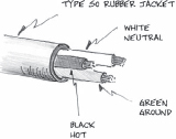
12/3 SO CABLE FOR JUMPERS
The 20-amp, 12-gauge wire is used because it matches up with the amperage rating of commonly used dimmers and connectors. All parts of an electrical delivery system should have the same amperage rating, or the chain will fail at its weakest link.
The most commonly used lighting connector is the pin connector. These have been around for many years, and in modern form consist of three metal pins that extend from a plastic housing. The pin in the center is for the ground wire. The pin closest to it is the neutral, and the remaining pin is used to connect the hot. Usually, the neutral terminal of any wiring device will have a nickel-plated set screw while the hot is the natural brass color, but this is a fairly recent standard which is not always seen on pin connectors. Although there are a few 60-amp pin connectors in use, the vast majority are rated at 20-amps. That is a good fit with the 20-amp SO cable and the 2400-watt dimmers.
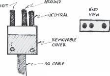
PIN CONNECTOR
Twist lock connectors have become quite popular in the past two decades. Notice that the blades have a slight L shape to them. When you press two connectors together and give a slight turn to the right, they lock together and will not come apart. (Sometimes it is necessary to tie pin connectors together.) Each of the blades is shaped a bit differently so that the connector will fit together only one way. This ensures that hots will not be accidentally be joined with neutrals or grounds. The only drawback is that the prongs or blades are much thinner and more delicate than those on a pin connector. They often require straightening. Pin connector pins are about the diameter of a pencil and are almost indestructible.
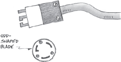
TWIST-LOCK CONNECTOR
There are dozens of different types of twist lock connectors that are intended for a variety of uses, and for many areas besides lighting. They are often used for chain motor power, and also to hook up sound PAs. When using twist locks for lighting purposes, you should make sure that you ask for a three-pin, 20-amp twist lock. Check the manufacturer's numbering system if you are matching existing plugs.
Solid wire can be bent into a hook, a shape that a terminal screw can easily grasp and hold down. This will not work with stranded wire because individual strands fray and warp out of shape, preventing the connection from carrying its full electrical load. SO cable should have terminals attached to the ends of the wires so that a firm connection is made when using pin and some other types of connectors. This kind of terminal is a small metal device that can be crimped onto the wire.

ELECTRICAL TERMINALS
Ring terminals have a closed loop and are available in either a straight or “flag” version. The flag type attaches at a right angle to the wire and is required for some kinds of pin connectors. You can tell which kind you need by looking at the inside of the connector. Terminal ends usually come with the device, but they can be purchased from an electrical supply house for repair work. Flag ring terminals will most likely have to come from a theatrical supplier, because it is an unusual item for most electrical supply houses. It is generally not necessary to use terminals for twist lock plugs because of the way their connections are made.
Touring shows and concert lighting companies use a number of different connector types for special purposes. Cam locks are used to connect heavy feeder cables. Cam locks are more commonly used for welding cable. Large multicable connectors may have up to forty, 20-amp pins. Some people refer to these simply as “military connectors.” There is a similar type known as the Socapex that is smaller and designed for fewer conductors. When a multicable is prepared with many individual connectors at the end of its run, it is called a break out, or a fan out. This is done so that the cable can then be used to connect with individual lights.

CAM LOCK CONNECTORS ARE USED ON SINGLE CONDUCTOER FEEDER CABLES
IF THE PICTURE WERE IN COLOR YOU COULD SEE THE TAPE MARKS THE DIFFERENT HOTS AND THE NEUTRAL

BREAK OUT OR FAN OUT
In the past few years, it has become increasingly common to use data cable to operate digital equipment like color changers and computer control boards. This digital information operates at an extremely low voltage, and very small conductors are sufficient. Four pin XLRs are used for DMX information. These look like the XLRs that are used for mic cables, but mic cables have only three pins. That standard three pin version is used to control many moving fixture lights.
Any extra time spent in carefully installing connectors will pay you back several fold in the long run. Make sure to use the correct terminals, and to properly connect the strain relief. The strain relief is a kind of clamp that keeps the wires from pulling out of the connector. Sometimes extra insulation is cut and placed in the strain relief to ensure a tight fit.
TROUBLESHOOTING
It is important to keep lighting equipment in proper working order because of the safety concerns that arise anytime 110 volt lines are used. Any piece of equipment that has been damaged or that is known to be faulty should be set aside for repair. It is quite common to see a wire pulled out, or a connector smashed by some heavy object. Sometimes it is difficult to tell just what part of a system is at fault. There are some easy ways to isolate the source of an electrical difficulty.
If a light fails to come on when you patch it into its circuit, unplug it and replug an adjoining light that is known to work into the suspect circuit. If the second light comes on, then power must be getting to the end of the jumper, and the problem is in the light itself. It is most likely a lamp failure. Most of the time a blown lamp is obvious, but if it is difficult to tell by eye, then use a continuity tester on the lamp's contacts. If the filament is intact you should find continuity through the bulb using a Volt-Ohm-Meter.

VOM
CAN BE USED AS A CONTINUITY TESTER
Quite often the lamp may not be seated properly in the socket, and you can try wiggling it back and forth, with the power off, of course. Bad contact with the socket is a very common problem. Especially with bi-pin lamps like the EHG or the HPL. Heat expansion and contraction often cause lamps to work themselves loose. Resetting the lamp in the socket may well be only a temporary fix, and quite often the socket must be replaced if it has become corroded.
If the lamp is good, then the problem might be in the lamp cap and/or the connector. It is fairly common for a wire to get pulled out of either one of these. Try the connector first because it is the easiest to check.
Going back to the beginning, if the second light did not come on when you plugged it into the suspect circuit, then no power was present at the plug. Try plugging a test lamp into the drop box, or whatever location the circuit came from. If there is power at the drop box, then the jumper is at fault. If there is no power at the drop box, double check to see that you have patched correctly and the dimmer is good. If all of these things are in order, call a licensed electrician to find out what is wrong with the building circuitry. This is almost never the case, but it does happen. Double-check all of your own work first.
You can see why it is easier to troubleshoot your electrics while they are still on the ground. Many times an electrician may make up a special test light with a theatrical connector and a small bulb to use in testing circuits. It can be carried in a pocket, ready for use. A cue light or a dance spotting light will work just as well.
SPECIAL EQUIPMENT
There are a few pieces of equipment that do not fit easily into any of the previous categories. You might not use them on every show, but they do come up often enough.

Bumpers are used on electrics whenever there is a working piece on the next batten that might get fouled in an instrument or knock one out of focus. A bumper is a section of flat iron bar that has been bent into a circle about 18 or 20 inches in diameter. A C-clamp is used to fasten the bumper to an electric at a convenient location along the pipe. You will most likely need three or four for each electric.

SIDE ARM
A side arm is used to attach lighting equipment that will not fit on the pipe in the normal way. It is really just a long extension of the yoke and C-clamp. Side arms can be used for other purposes. One of these is to prevent a batten from rolling. Lights are usually hung with the yoke pointing straight down, but sometimes there is a reason to yoke them out to the side, or even to hang them standing up on the top of the pipe. Sometimes this is to get a better angle with the light, and sometimes it is just a matter of getting more units into less space. At any rate, hanging lights to the side makes the pipe want to roll downward, and if you let this happen it will change the focus of the lights. To keep the pipe from rolling, fasten a side arm to the batten near one of the lift lines and then attach the pipe part to the aircraft cable with some tie line.
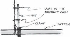
USE A SIDE ARM TO KEEP A BATTEN FIXED
A side arm can also work as a makeshift pipe wrench when the actual tool is not available. It can be used to tighten pipes into flanges or boom bases.
Booms are vertical pipes used to hang lights. Sometimes they are attached to the wall or some other architectural feature, and sometimes they are freestanding on a base. Boom bases are very heavy cast metal pieces that keep the pipe from falling over.
There are practical limits to how high you can take a boom before it is unsafe, and you must determine what that limit is for your particular situation. Sometimes it is possible to tie up the top of the boom as a safety. It is best to hang lights on a boom so that the load is balanced rather than to hang all of the fixtures on one side. A lighting tower is a much safer alternative when there is a large number of fixtures to hang and/or they must be very far off the floor. More information on towers can be found in the “How Do You Make…” chapter.

SHOP-BUILT BOOM BASE
You can quite easily make shop-built bases from some ¾" plywood and a pipe flange. Use two layers of plywood for the base, and be sure to securely bolt the flange to the wood (this is very important!). Use 1½" black steel pipe and the appropriate type of screw-on floor flange. Use a number of stage weights on top of the plywood to hold the base in place, or lag bolt it to the floor. These shop-built bases are excellent in a reduced size for small, one fixture floor mounts, especially if these lights are “rovers” (lights that get moved around during the show). If there is only one light on a floor mount, remove the clamp from the light and bolt the yoke directly to the wood.

MAKE A SMALL BASE FOR “ROVER” LIGHTS
FOCUSING
Focusing lights is like dancing a tango. You need to observe what your partner is doing, and be ready to respond. The lighting designer leads, and if the technician follows well, the job can be done very quickly. Sometimes on tour where the designer is not available, focusing is done with the stage manager instead.
Use a six- or eight-inch crescent wrench to focus lights. Some people use a safety line on the wrench, to prevent it from falling. The lights get hot in a hurry, so you might consider a pair of gloves, but they will definitely get in your way. If you are quick, the lights will not heat up fast enough to make the gloves necessary. Either a lift or a ladder is required to focus lights that are up in the air, which means almost all of those on an electric. It is best to have one person on the board to bring up the proper channels, two moving the lift, and one who actually focuses.
It is common for the designer to begin at one end of an electric and work her way down to the other end rather than to hop around from place to place. It is much faster not to have to move the lift any more than necessary. Most designers understand this. They will ask for the correct channel number to be brought up and then go to the proper spot to focus the light and just stand there and wait. The general idea is to focus the center or “hot spot” of the light on the chest or back of the designer, and then lock off the bolts that hold the light in place. Some designers will direct you by staring at the filament to see when it is brightest. (Yikes! But they really do this.) Some stand with their backs to you and watch where their shadow falls within the light. If a relationship of mutual respect is developed, the designer may simply trust that the electrician has the hot spot in the proper location.
Whatever method is used, the designer gives directions on moving the light. Up and down movement is called tilting. Side-to-side motion is known a pan. The designer might say pan left, and tilt up a bit. This usually means your left, but not always. Some designers just point: up, down, left, right, especially if there is a lot of noise. A clinched fist means “Stop, you've got it.” If you are exceptionally in tune with your focusing partner, you will most likely be able to hit them just right without so much talking, and they will just say “Lock it” when you've got it right. Locking means to tighten the bolts that hold the light in place. Tighten them enough to make it hold, but don't make it your life's work. The light won't be there that long.
If the light is an ellipsoidal, you will most likely need to make some shutter cuts. You may need to sharpen or loosen the focus of the light first by moving the barrel back and forth, just like focusing a slide projector. There is a knob on the top near the front that can be loosened to allow the barrel with the lenses in it to move back and forth to adjust the sharpness. Push in on the top shutter to mask the bottom of the light beam. Push in on the left shutter to change the right side. Very often, the shutters are hard to move and you will find that it is easier if you jiggle the handle back and forth a bit to get it started. Try not to change the direction the lamp is pointing, or you will have to start over. Shutters do not just travel straight in and straight out. It is quite possible to tilt them to a severe angle, but not always as far as the designer would like. The barrel on some fixtures can rotate when necessary, but don't plan on doing that for every light unless you are being paid by the hour.
If the designer is uncertain which light is casting which shadow, she may ask you to “flag” the light. This means to pass your hand or foot or some other convenient body part in front of the light. This will make the beam flash on and off, making it easy to spot.
Patterns or gobos must be inserted into a special holder before they are lowered into a slot next to where the shutters operate. It probably won't matter for a break-up pattern, but in order to read properly, patterns should be put in upside down and backward. Running the barrel for a sharp focus can make a world of difference with a gobo. On occasion, a donut is used to sharpen the focus even more. A donut of this sort is a black metal sheet that fits into the gel holder slot. It has a hole in the center about two inches in diameter. This device cuts down on ambient light and has a dramatic effect on how pronounced the projection appears. A larger hole will emit more light. A small one will sharpen the focus more. If you would like a quick peek at what effect the donut will have, make a circle with your hands and hold them in front of the light.

USE YOUR HANDS LIKE THIS FOR A QUICK IDEA OF HOW A DONUT WILL AFFECT THE LIGHT
If you are focusing a PAR can, it might be necessary to change the direction of the lamp in order to adjust the direction of the oval. There is a ceramic socket in the back of the light that can be used for this purpose. There is a limit to how far it will turn in one direction, so it may be necessary to try both ways. Some PAR fixtures use a ring around the outside to “spin the bottle” of the reflector.
If you are focusing a Fresnel, you may need to change from spot to flood. Some fixtures have a crank on the back or side, but most have a knob on the bottom. Loosen it and move it in the right direction. Flood forward, spot back.
When the light has been set, put the gel frame in and move to the next light. If you are on a lift, you can most likely reach several lights before moving. When you are ready to go, tell the fellows on the deck. If you say, “Moving stage left,” they will know exactly what to do. If you say, “OK”, or “Go”, or make some other nebulous statement they may not. Remember that moving onstage means toward the center, and moving offstage means toward the wing of the side you are closest to.

Be sure to employ any and all of the safety devices that come with the lift you are using. Follow the instructions given in the instruction booklet. If you do this there is very little chance of the lift being knocked over. The same cannot be said if you choose to ignore the safety rules. Never set up a lift on a raked stage for any reason. It is a good practice to always have two stagehands move the lift, and to stand by while work is being done.
If there is ever a hold-up of some sort, be sure to announce what it is and that you are working on the problem so that people on the ground have some idea of what is happening. As a result they will be less frustrated and impatient.
OPERATING A FOLLOWSPOT
Followspots are used in many productions. In some areas of the country they are known as a frontlight, or perhaps simply as a spotlight, or spot. As the name implies, a followspot is a lighting instrument used to follow the action of a play. They are the original moving fixture lights. The basic idea of a followspot is for the operator to “open up” on an actor and then stay with them until the scene is over, no matter where they may move on the stage. This ensures that the audience's attention will remain focused on that particular actor. A spot may also be used as a special to highlight an inanimate object, and other times, it may be used as effects lighting. Spots can range in size from tiny club instruments of about 1000 watts to giant behemoths used in sports arenas. IATSE stagehands and others are often called upon to run a spot for concerts, ice shows, wrestling bouts, and other entertainments, as well as for theatre shows. Information about those techniques is included here in order to better understand the full range of followspot operation.

THIS SPOT IS USED IN A LARGE SPORTS ARENA
Traditionally, a followspot in the theatre was used to create a hard-edged circle of light that said, “Look at me, I'm singing now.” This approach is unmistakably presentational, and still works well for 1950s musicals and other shows of that nature. In recent years that style has often given way to a more subtle method that uses diffusion gel in the spot. It creates a softer beam of light that can be used to simply highlight an actor and give them focus, without the unnatural look of the hard-edged circle. Spots aren't just for musicals anymore.
In earlier times, followspots used a DC arc between two carbon rods to create an incredibly bright and white beam of light. A large rectifier unit was used to supply the necessary DC current. A pair of copper clad carbon rods was clamped into two terminals in front of a parabolic reflector that had a hole in the center for the rods to pass through. A motor and gear system was used to slowly move the two rods together as they were consumed by the heat of the arcing electricity. It was necessary to maintain a precise gap between the two rods in order to ensure maximum light output. The gap itself had to be positioned in just the right place with respect to the reflector in order to work efficiently. New rods had to be inserted and “trimmed” several times during a single performance. Keeping the spot running was a difficult process that required almost constant attention and a very experienced operator.
Carbon-arc lights had one other really problematic aspect in that the burning rods gave off toxic fumes, which in more recent years required some sort of exhaust system. Modern spots use a sealed-beam arc lamp like the Xenon or HMI and don't have the same problem. These lamps still require a rectifier unit to provide the necessary DC current, but the arc terminals in the lamp itself aren't consumed by the arcing process (at least not during any one performance). This means that the lamp can be permanently clamped in position at the exact focal point vis-à-vis the reflector, and will always be in focus. This greatly simplifies running the spot. Xenon lamps are very expensive up front, but reduced maintenance costs, and not having to buy carbon rods more than offset the expense.
A few theatres and/or arenas may still use carbon-arcs, but most of them have disappeared. Other venues may have lights that were converted from carbon rods to a sealed-beam. However, you can still find an example of carbon-arc technology in large outdoor spotlights that are used to attract patrons to gala openings. The brilliant light beams playing across a nighttime sky are visible for miles. These fixtures require an extremely bright light source that a carbon-arc can easily produce, and since they are operated outdoors, the fumes are less of an issue. They have been around at least since WWII when they were used to search for enemy planes in the sky. They have an incredibly long throw.

XENON IS A RARE GAS THAT CAN CONDUCT ELETRICITY, AND EMITS LIGHT WHEN EXCITED BY ELECTRONS.
THE GAS IS UNDER PRESSURE, AND THE LAMPS REQUIRE SPECIAL HANDLING.
Followspots are typically used from a position in the rear of the theatre and require a lamp that is much brighter than that used in a standard fixture, but there are smaller spots that can be fitted with ordinary quartz lamps like the FEL or CYX. It would be possible to run those particular lamps off a dimmer, but brighter arc-type lamps are not dimmable. If the voltage supplied to them decreases below a certain point, the arc will simply sputter out. Instead, most followspots use a mechanical device to vary the light intensity. Other mechanical devices can change the size/shape of the beam, and the color of the light.
Most of the time a followspot has a base that is used to hold up the light from the floor, rather than hanging it from a pipe like other lights. They are generally too heavy to hang and also require room for the operator, and to swing about themselves. One exception to this is the “truss spot.” Truss spots are used extensively in the concert business, where they are literally a spotlight that is mounted on top of a section of truss, which is flown out over the stage or audience. An operator sits on top of the truss to run the show. One artistic advantage is that the angle of the light from high above is much more dramatic than the typical flat beam from a spot in the rear of the house. At a concert, haze in the air reveals a shaft of light extending from the truss to the stage. Most of the reason for using truss spots in a concert can be found in the effect created by these moving colored beams.
For a play, a high angle spot is often used when a subtle halo of diffuse light is required to highlight an actor, but it can also be used in a variety of other ways. In a theatre situation, close spots like this are often mounted at a front-of-house lighting position, or from a tower especially installed for the purpose. It is not unusual for a tower of this sort to be located offstage near an “in one” entrance. Sometimes an ordinary fixture like a PAR or ERS is fitted with special hardware, and is used in place of a dedicated spot fixture because of the tight quarters. The bus and truck tours of Cats used two old beam projector lights as followspots, and they were suspended from a truss used as the first electric. A series of gel frames were tied to the operator's platform and were individually inserted into the holder to change the color of the light. There was a section of hollow pipe on the side of the light to use as a sight. Crude, but very effective.

Different followspot models have different mechanical parts, but almost all have the most common few. These include a dowser, iris, stripper, and boomerang.
A dowser is used to vary the intensity of the light output, and to black out the spot so that no light gets to the stage. The dowser is a metal disc that can be rotated into the light beam. This occurs optically in a manner so that the apparent change is a dimming effect rather than seeing an eclipse-like change to the light beam. On some really large spots, the dowser knob controls an apparatus that resembles a barn door of the type used on a fresnel light. The two halves of the dowser plate are pulled in from either side for a more effective mechanical shuttering effect.
On most lights, the dowser control is on the top of the light itself and is a steel rod with a large plastic ball on the end. Different manufacturers arrange the controls differently, but most of the time the dowser is the control nearest the back end of the light.

TYPICAL CONTROL PLACEMENT PLAN VIEW
You can make small adjustments in the amount of the light beam that is blacked out, but it is difficult to stop at precise points. Some operators make a mark on the housing in order to stop the lever at a predetermined place, but most of the time, a certain value must be intuited by the “spot op”. Running a followspot is somewhat more artistic than just punching a button at the lighting console.

Dowsers absorb a lot of heat, especially if they are not opened up for a long period of time during the show. Even so, it is generally not a good idea to turn the spot on and off, as this can actually be harder on the equipment than just leaving it running. Plus, you may have a difficult and noisy time getting it to start back up. Virtually all spots have some sort of fan that cools both the power supply and the light itself. This fan should be allowed to run for a while, even after the spot is turned off, in order to avoid overheating the lamp.
Another commonly found control is the iris. An iris is a system of thin, curved metal plates in a movable housing. The plates overlap one another, and when an outer retaining ring is rotated, the thin plates form a larger or smaller circle. They really act a lot like the kind of ordinary shutters found in a Leko, except that the shape they form is round rather than square. The same kind of mechanism can be found in some cameras.
Changing the size of the opening varies the size of the pool of light that reaches the stage. If the spotlight is located far from the stage, you will need to iris in for the distance, while being closer will mean a larger opening. The design of the show, and individual cues, may require a larger and/or smaller size as well. The iris control knob is often the closest one to the front of the light.
It is sometimes possible to completely black out the light by closing the iris in all the way. Do not do this. The iris is a delicate device and it is very close to the light source, which is extremely hot. If you block all of the output with the iris, the thin metal plates will heat up very rapidly. They will warp out of shape and be ruined.
TURNING THE OUTER RING WILL MAKE THE CENTER OPENING LARGER OR SMALLER
IRIS
Some spots have an additional device known as a “trombone” that can also be used to vary the size of the spot. The trombone is a handle on the side of the light that can be pulled back and forth along the length of the spot (hence its name, in action it is like a slide trombone). The trombone works by changing the relationship between the light source and the lens mechanism. Some operators use a combination of the two controls in their work. Most of the time in theatres the distance of the talent from the spot position remains fairly constant, and the trombone is not necessary. The trombone is more often used for arena acts like an ice show where the skaters may move from 300 feet away, to only 100, in a matter of seconds.
The iris can be used to create a variety of spot sizes that are selected because of artistic reasons. The largest is generally the “full-body” size, which is large enough to include the entire body of the actor. Sometime you may need to go larger than this to include two characters standing right next to one another. “Three-quarter” means from the knees up and including the head. It is very rare for a designer to ask for a shot that does NOT include the actors head and face. You should always strive to keep the head in the light no matter what. The next smaller shot is the “waist,” and then finally the “head-shot.” Sometimes there are special instructions like “head and shoulders, but try and stay off the white guitar as much as possible,” which are fairly descriptive in their own right.

COMMON SPOT SIZES
The “chopper,” which is also known as a “stripper,” is used to cut off the top and bottom of the light beam so that it is more like a horizontal strip. If you then iris out to a very large size, there will be a strip of light perhaps as wide as the stage. This sometimes happens when a designer wants to have lots of lateral coverage for something like a curtain call. In reality, this effect is rarely used because it is not very attractive.
EFFECT OF A CHOPPER ON A CONTAIN CALL LIGHT
Virtually followspots have some sort of color changer. This device is often called by the slang term “boomerang.” Normally, six different colors are possible. The gel is loaded into round frames that are designed specially for that particular light. The two halves of the frame are fastened to one another with small brass brads like the kind used to hold papers together, and are also used on other types of gel frames. It is important to do a really neat job of inserting the color media into the spot frames because they must slide smoothly beside one another while in the light. If either the brads or the gel stick out to the side, the frames will have a tendency to get hung up on each other during the show.
In the light itself, there are six flanges for the frames to slide onto. The flange that is nearest the rear of the light is for frame one. Six goes toward the front end of the light. This is the standard numbering method and it is important to maintain proper orientation so that the correct color will be brought up during the cueing process. The original choice was a somewhat arbitrary selection, but has become the standard method and should be followed.

COLOR CHANGER OR “BOOMERANG”
There are six levers on the outside of the housing that can be used to bring a particular frame up into the path of the light beam. When a color is up, it filters out all but the precise wavelengths relating to that color. The desired light color passes through, but the remainder of the light waves are stopped and converted into heat energy. Over a period of time, the gel will burn out because of that. There is also a lot of heat from the lamp itself. Gels with heavily saturated colors will last longer if they are placed in the number 5 and 6 positions away from the heat. Most lights have a button you can use to cancel out a gel frame and make it drop back out of the light beam. Alternatively, if you pull a different frame lever all the way down, the first color will be automatically cancelled.
A color correction gel is often used when television is involved, so that the color temperature of the light from the followspot will match the color temperature of the rest of the lights. It might be used all the way throughout a show. The term “no color” is used to indicate that no gel is to be used on a particular cue.
Running a followspot requires a lot of concentration. Professional stagehands are expected to come in and run a show cold, without ever having seen any the action of the piece. Generally, there is a Lighting Director to call the cues for a musical act, ice show, or circus, while in a theatre show, the cues are called by a Stage Manager, or possibly by a spot operator who travels with the show and is familiar with it. There are standard methods of setting up a show and of calling cues, which make it possible for an experienced operator to understand the cues with a minimum of explanation.
The spot-ops are usually given numbers in a clockwise rotation. In an arena, this means starting upstage left and moving around to upstage right. In a theatre show, the house right spot is usually number one and the house left is number two. Traditionally, most theatre shows are designed for two spots, but it is not unusual to have three or even four if the budget will allow it. The numbering system is used to simplify cue calling, and in case of a change in personnel. It is very important for each operator to remember their spot number.
Sometimes the cue caller will assign each spot a “home position,” which is kind of like a default setting in a computer. A call to go to your home position is a way for the cue caller to reset the spots in a familiar, predetermined pattern. This happens more often in concert lighting where home positions are things like the lead singer or the stage right guitar player. In theatre shows, the same spots tend to pick up the same characters in the play so that it is easy for them to remember who to hit.
A typical spot cue might go like this: “Stand by for spot one to pick up the woman in the red dress up left in a frame one, and spot two on the man in the black suit down right in a frame five. Spots standby and . . . Go.” If you are spot one you should push down on the first lever on the boomerang to load frame one. Spot two should do the same with frame five. On the go, both spot ops should run their dowser levers to bring the light up on the target specified by the cue caller. From that point on it is just a matter of staying with the target until the next cue is called.
Quite often, there are instructions about the timing of fades, intensity of the light, size of the spot, etc. Very often, cue callers make a blanket statement that fades should be on a one or two count unless there are instructions to the contrary. They might ask for a very long fade like a five count for a very emotional moment, or for the spot to go out all at once on a bump if there is a general blackout. Good spot operators develop an ability to “get in tune” with the tempo of the the show, and adjust their actions intuitively.
Most of the time in a theatre show, a spot will stay with the same gel color for an entire cue, but on occasion it is necessary to go from one frame to another with the light still on. Many cue callers express this by saying “roll to frame # so and so,” or sometimes “cross fade.” This could be on a bump, but often they want a smooth transition from one color to another. You can do this by slowly engaging the second frame to the point where it cancels the first one. That first frame will want to drop out quickly, but if you catch the lever with your finger you can gently lower the outgoing gel from the light beam in an artistic manner. Running a theatre show is generally a somewhat more subtle enterprise than a concert or circus.
It can sometimes be difficult to locate the next frame lever if you are concentrating on watching the stage and moving the spot to follow an actor. It is helpful to remember that there are six levers, and that quite often number three or four is longer so that you can find it by touch alone. Some operators put tape on number four, for the same reason. It is easy to find numbers six or five by counting backwards from the far end.

USE YOUR THUMB AND FINGERS TO ARTISTICALLY CHANGE FROM ONE FRAME TO ANOTHER
Most of the time, operators are asked to stay on one person until the light fades out, and then to fade back up on another subject. On occasion, the design calls for the light to move directly from one target to the next. The cue caller may express this by saying, “slide over to so and so,” or perhaps “drag your light.” In this instance, you simply move discretely from one place to the other. This often happens when there are two actors close together and the idea is to trade one for the other. If you can time it so that this happens as they pass one another, the audience may never notice it, especially if diffusion gel is in use.
A diffusion filter causes the light to change from a sharp edged beam to a soft edged beam, rather like the difference between an ellipsoidal and a Fresnel. There are different values of diffusion so that the edge of the beam can be anywhere from a little bit fuzzy to practically unfindable. It is much more difficult to run a light with a diffuse edge, especially if the stage is bright and the difference in value is hard to see. It is generally easier to keep track of things by choosing to watch the pool of light that has an actor in it, rather than on the actor in a pool of light. A subtle, but very real distinction. If things get really bad, you may have to move your light around a bit to see if you are still on target. If it is that hard for you to see, then probably no one else will notice that you have done it, especially if you manage to avoid running the light off of the actor's face. As a general rule, you should avoid jerking the light around unnecessarily. Stay still even if you are slightly off target, wait for the actor to move some, and then readjust.

TRADITIONAL HARD-EDGE SPOT

SPOT WITH DIFFUSION MEDIA
It is often difficult to have your spot lined up on the actor when the light comes up. It is very distracting to have a light appear near center stage and then uncertainly wander around until it finds the woman in the red dress upstage left. You can avoid this by using some kind of targeting device. This can be as expensive as a high-powered telescopic rifle sight, or as low tech as a bent piece of wire. There are a number of proprietary devices that are made specifically for this purpose and new ones are developed from time to time. You should try different things and find one that works well for you personally. Using a sight of some sort is a really important step that can enhance the artistic qualities of your spotting work.

USE A SIGHT TO IMPROVE YOUR AIM
The sight is a personal tool, and you will need to move it from one spot to another each time you work. It is common practice to attach the sight, of whatever type, to a powerful magnet so that it can be easily mounted on the steel housing of the spotlight. Then it is just a matter of adjusting the sight so that it is accurately centered on the light beam coming out of the spot. For best results, make your adjustments at maximum distance, with the iris as small as practical.

SIGHT ON A FOLLOWSPOT
There are some rather quirky spot instructions that come up on a fairly regular basis, often enough so that they have actual names. One of these is the ballyhoo. This occurs when the spots criss-cross the audience area in a figure-eight pattern, or perhaps a swirl. This is generally done to excite the crowd, as though the lights are searching for someone. It is even more effective if you change speeds occasionally, as though you are slowly searching, then speed over to another possible target, then slowly search again.
Another technique is to pan back and forth over a group that is too large for one or more spots to cover effectively. This works well for a line of actors at curtain call, or perhaps even a line of elephants on the back track near ring two.

PAN BACK AND FORTH
BALLYHOO THRU THE AUDIENCE
LAMPS
There are many different kinds of lightbulbs used in the theatre, but they all have one thing in common, which is that they are all expensive. Lamps that sell the most tend to be less expensive due to the economy of scale in manufacturing. You may want to consider lamp replacement costs when selecting which brand of lights to buy. Lamps often specify how many hours they are expected to last, and that can can also be a consideration when making a selection. Some Xenon lamps for followspots list for hundreds of dollars and come with a guarantee that they will last for a certain number of hours.
Most lights today use some sort of quartz-type lamp, meaning that the glass used to create the vacuum chamber covering the filament is made of a special quartz glass. This type of glass is able to survive extreme heat, and as a result, the glass envelope can be made relatively small, with the glass close to the filament. This makes it easier to design the structure of a fixture that contains a high-wattage bulb.
A 1,000-watt filament puts off a lot of heat. It is important to remember to never touch a quartz lamp—not when it is hot because you will be severely burned, and not when you are installing it because dirt and oil from your hand will get on the surface of the glass. It will turn black from the heat, and might cause the lamp to explode. The black spot on the lamp will cause more heat to collect on that side and the lamp will fail prematurely. It is usually enough just to wipe a dirty lamp off with a clean cloth, but rubbing alcohol is good if it is really dirty. Avoid highly flamable solvents.
The American National Standards Institute has laid down specifications for lightbulbs so that any bulb of a certain type base will fit into any socket meant for that base, regardless of the manufacturer. The most often used bases in the theatre are the screw base, prefocus, bipost, and the two pin. Most of these bases have different sizes, usually the regular standard, or the much larger mogul. Screw bases have smaller versions, such as intermediate and candelabra.
Each type of lamp has a specific ANSI code, which is its name. For the most part, these are three-letter codes like HPL, BTN, or EHG.
