
CHAPTER 16
FULL-SCALE PATTERNS
Full-scale patterns are used to produce work that does not lend itself to an ordinary cut list. Some units of scenery are so oddly shaped that the normal methods are simply not possible. This frequently occurs when lots of angles are used, or if the shapes are curved. The full-scale pattern technique allows you to mark framing parts directly from the patterns, or in some cases the pattern is marked on plywood that becomes a part of the unit. Most of these techniques have been touched on in other chapters, but it seems best to organize them all in one place. Theatre scenery tends to have very fanciful shapes and profiles that require the builder to be more inventive than carpenters engaged in general construction.
Throughout history, painters have used a gridding technique to reproduce scale drawings into full size. If a drawing has been rendered in a ½” scale, each ½” on the drawing is equal to 1'- 0" in full size. You can use this method by dividing the drawing into ½” squares, and the surface you would like to transfer the design to in 1'- 0" squares. It is possible to transfer the drawing to the larger scale one square at a time with a high degree of accuracy. Scenic artists use this method daily in their work. If a profile piece of scenery is to be constructed, the same technique will serve the stage carpenter well.

THERE ARE SOME THINGS YOU CAN'T JUST MEASURE, AND MARK WITH A CHALK LINE
USING A GRID
Gridding off a profile quite often requires the input of a scenic artist. Most often the carpenters will lay out plywood, grid it off into one-foot squares, and then request that the scenic artist or designer mark the profile. Depending on the personalities involved, you might wind up marking the outlines inside the squares and then just getting them checked by a more artistic member of the team. (Unless, of course, YOU are that person.)

Once the outline of the piece has been marked in charcoal, it is a good practice to retrace it with a Sharpie marker so that the line is clearer. Charcoal tends to vibrate off the plywood during the cutting process, and having a clear and indelible mark makes the job of cutting much easier. The more complicated the work is, the more important it is to retrace. One word of caution: laquer-based pens can be difficult to paint over. This is especially true if the paint is a light color.
After the design has been laid out, you will need to cut the profile edges with a jigsaw. The teeth on a jigsaw blade cut on the up stroke so that the saw is pulled against the work. That keeps the saw from bouncing around so much. Unfortunately that means that most of the tearout tends to occur on the top of the plywood. You can mark the pieces on the backside so that the front will have a cleaner edge. If the design is really complicated, this can be more trouble than it is worth, and it may not be necessary.
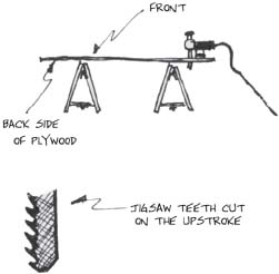
MARK THE DRAWING ON THE BACK WHENEVER POSSIBLE
You can also reduce tearout by cutting with the grain. You may recall how ripping creates less tearout than cross cutting. You may be able to line the plywood up in such a way as to keep as many lines as possible running with the grain of the wood. Obviously, this is problematic when cutting curves. But tearout is also less if you cut at an angle that pulls on the wood fibers rather than pushing them. If you are cutting at an angle to the grain, one side of the kerf will be pushing, and the other side will be pulling. Make sure that the keeper piece is on the pulling side of the kerf. If you have a large curve it is possible to reverse the angle of your cut where the grain direction changes and make the entire curve smoother.

CUT SO THAT THE BLADE PULLS THE GRAIN ON THE SIDE YOU WANT TO KEEP
Very often, the profile you are working with will be on several sheets of plywood that must be joined together later. It is difficult to get the cut on one sheet to line up exactly with the cut on the next one. This is especially true of marks that were made with charcoal and markers. It is often better to leave extra material at the joints and to trim that excess off after the panels have been joined together.
LAYOUT PATTERNS
A related method uses a full-scale pattern to mark angled pieces where dimensions are known, but not angles. This often occurs when building scenery. It is generally more accurate to use this method, which does not include determining the angles from a scale drawing. “Scaling” from the drawing can lead to some fairly large errors, as the drawing is so small in relation to the true size of the scenery that a pencil dot can be as much as an inch. If you make a large pattern from dimensions on the plan, you are using the best information to build the piece.
The drawing shows a hard framed portal that must be constructed from steel square tube. The offstage edge is square, with lengths of steel meeting at 90-degree angles. The inside profile is full of odd angles, and we don't know what they are. You are given the dimensions of the scenery and the locations of the angled intersections. That is all the information that is required to do a layout of the portal.

CONSTRUCT THIS HARD PORTAL FROM 1 ½" SQUARE TUBING AND ¼" PLYWOOD
The first step is to mark the outside and inside profiles of the shape on the floor. The floor is a good place for this procedure because it requires no preparation other than sweeping. The floor is always there and doesn't cost anything. Sometimes it makes more sense to do the layout on plywood, and other times you may want to use paper if the size is really small.

You will be marking the framing pieces by laying them on top of the drawing, and there is no need to move the drawing around. This particular unit is made from welded steel, so a concrete floor is an obvious choice for fire safety reasons. It is fairly large, and it would be difficult to lay out enough platforms to do a wooden block jig. The jig seems less necessary since only one copy will be built. Heat distortion is less of a problem on a large flat piece that has relatively few parts for its size. These are all factors to consider when deciding how to go about your work. Start the layout procedure by snapping a chalk line on the floor in a convenient location.
Form a 90-degree angle line perpendicular to the original by using one of the following methods.
Use a sheet (or several sheets) of plywood to form the angle. Lay one edge of the sheet on the line, and draw along the adjacent side to form the 90-degree angle. This is much more accurate than using a framing square because the plywood is so much larger, and the proportional amount of error that can creep in is much smaller.

As an alternative you can use the “3–4–5” method of creating a right angle. It is stated that for any triangle with sides that are 3, 4, and 5-units long, the corner formed by the intersection of the 3-unit and 4-unit sides will be a right triangle. This holds true for triangles that are multiples of these numbers such as 6–8–10, or 9–12–15.
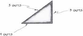
USE THE MAGIC TRIANGLE TO ESTABLISH A RIGHT ANGLE
Measure along your base line 12'- 0", and establish two points of reference. Then use two tape measures, one to measure up 9'- 0", and the other to triangulate the 15'- 0" between the 9'- 0" mark on the tape, and the 12'- 0" mark on the floor. That will establish a right angle. This technique is easiest to do with three people, one to hold the end of each tape measure on its respective mark, and the third to move the tapes back and forth until the 12'- 0" and the 15'- 0" marks are aligned with one another. Make sure that you are consistent about which side of the tape measure you are using. Drawing a line through this point and the original corner mark will establish a line perpendicular to the base line.

USE LARGER MULTIPLES OF 3, 4, 5 FOR GREATER ACCURACY
Once the base line and the 90-degree tangent have been established, you can plot the remaining points. Measure along the x axis to determine the width of the unit. It is possible to establish another 90-degree angle for this line, but it is much easier to simply measure twice, one toward the top and once at the bottom, and connect the dots.

MEASURE OVER TWICE AND SNAP A NEW TO MARK THE OTHER SIDE
The same method may be used to establish the top line of the unit. The remaining points are plotted according to their measurements from a known position by following the dimensions shown on the sketch. Often it is helpful to think of the layout as a graph with an x and a y axis, and the layout of the remaining points is a process of measuring from these axes. The widths of the two leg bottoms can be measured directly from either side of the portal. The remainder of the points that establish the diagonal lines can be plotted up from the bottom and over from one of the sides. The lines between the points can be drawn in with a straight edge, or if the distance is too great, use a chalk line. Whatever the method, it is best to finish by darkening in the line with a Sharpie so that they will be easy to see and less likely to be accidentally swept away.
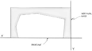
PLOT POINTS IN RELATION TO THE X AND Y AXES. THEN CONNECT THE POINTS WITH STRAIGHT LINES
The next drawing shows how the portal is divided into several different parts, or units, and how the framing is to be placed. The decisions about where the break lines fall are made in accordance with the realities of what size materials are available, and what it is reasonable to expect humans to carry and assemble. Generally speaking, fewer parts equal less expense, but they can be much more difficult to assemble and transport. Try to make units that can be carried by no more than four stagehands. If it takes more than that the piece is probably too large.
Also look for natural break lines in the design of the scenery itself. Quite often there is already a difference in paint color, or a piece of trim running along the scenery. It is clear that your break lines will show much less if you follow the same path.
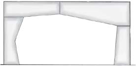
DIVIDE THE PORTAL IN TO BUILDABLE PORTIONS ALONG REASONABLE BREAK LINES
The method of marking the separate sections should be intuitive, and it must be decided on a case-by-case basis. Experience will teach you the best ways to do that, by observing where the shape changes direction. There is a trick that makes marking the actual framing members a bit easier.
The steel square tube that was specified to frame this portal is 1 ½” wide. Rip a scrap piece of plywood to that width and use it to mark the placement of the framing members. Lay the jig along the outside edges of the pattern and use it to make a mark 1 ½” to the inside. Take care to properly mark the overlapping of the framing, accurately mapping out which sections extend all the way to the side and which ones stop short. Measure the proper placement of all the required toggles using the same method as described in earlier construction chapters. Use the “measure ¾” to either side of the center” approach.
This portal will be covered with sheets of plywood, so take that into consideration when deciding where the toggles should go. The 1 ½” square tube is wide enough to join the seams of adjacent plywood panels using tech screws. Your 1 ½” wide marking tool should make it easy to mark the actual sides of the toggles. When all of these steps are complete, and you have established your pattern, it is time to begin marking the actual pieces to be cut. Notice that you have not formed a cut list, and that we do not yet know any of the angles involved.

Marking the pieces is a matter of laying a section of the square tube on the pattern, and then using a straight edge to transfer the angle and the length to the tube. Make certain the piece of tube is flush with all the edges of the pattern except the one you are about to mark. Close one eye as you adjust the straightedge so that it is lined up with the mark on the floor. The tricky part is to hold the marker so that it is directly above the line on the floor. There is a tendency to mark the piece with the correct angle, but too long or too short. It takes a bit of practice to get this technique.

Lay the square tube in the chop saw, and adjust the saw until it is set at the proper angle. Lower the blade and sight down the side of it to check for proper alignment. This is rather like looking down the length of a board to see if it is bowed or warped. If you are using this technique on a wooden structure, substitute “power miter box” for “chop saw.”
After the angle has been cut, lay the resulting piece back down on the pattern to check it for the proper size. You may want to refer back to the discussion of angles in Chapter 11 that talks about the relationship that angles have to one another in the same shape. Many of the angles in this project are the same. It is, of course, easiest to cut all of one angle and then all of another. If you are ever uncertain which other angles are the same as one you have just cut, put that first piece down on the pattern in various places to look and see. After all of the pieces of square tube have been cut and laid in place, the full-scale pattern they are laying on makes a wonderful layout jig for welding.

USE THE STANDARD METAL FRAME TECHNIQUES