
CHAPTER 13
BUILDING STEPS
Actors can't get from one stage level to another without stairs. It is the rare stage setting that does not include them in some way, whether just one step up to a low platform or as a long set of backstage escape stairs. Stairs come in many different types that may be constructed to fit a particular need, but there are some properties held in common by all the various types.
There are three main parts to any set of stairs. The treads are what you step on when going up or down. Risers are the part of the unit that “rise” from one tread to another, and the carriages are the side pieces used to “carry” the weight of the entire unit. Steps vary greatly depending upon the type of materials used, steepness, whether they are left open or boxed in, and stylistic differences.

MANY DIFFERENT PARTS WORK TOGETHER TO CREATE A SET OF STAIRS
STEP BASICS
There are a few general concepts to understand about how steps work. Mostly these have to do with the way the human body controls itself while moving through space. Everyone has tripped over a section of sidewalk that is suddenly higher than the surrounding walk. You have also sat down in a chair that is lower than you think and had a sudden sensation of falling. This happens because the body accustoms itself to certain distances and rhythms and comes to expect them. It is the same principle that makes it possible for me to type these words or for a musician to play the piano without looking at the keys.
When climbing a set of stairs, your body tends to develop a rhythm to its movement, and if one of the steps is of a different height, then it is quite easy to trip on it. For this reason it is important that all risers be of the same height and likewise for all treads to be of the same depth. Without that, a set of stairs can be very dangerous.
It is possible to determine equal risers by dividing the total rise by the number of risers and also equal treads by dividing the total run by the number of treads. Stage stairs are usually easy to plan because stage platforming tends to be in even amounts. If a platform is exactly two feet tall you can determine riser height in even numbers. If you want to have a rise of 6 or 8 inches (commonly used increments), then you can divide that riser height evenly into a platform height of 2 feet, or 24 inches. A 9-inch rise wouldn't work because that height will not divide cleanly into 24 inches. Nine-inch risers will fit neatly, however, with a platform height of 36 inches. Dividing the height of the platform by the individual riser height will produce the number of rises required. That number should be one more than the total number of treads, if the platform itself is used as the top step. The number of treads will equal risers if the top tread is level with the top of the platform. Usually it does not, because that increases the size and expense of the step unit.
In general construction, figuring stairs is more complicated because the height of the second story of a building is rarely so even a measurement, but tends rather to be an amount like 9'- 1 ¾". Even so, the process remains the same.

3 TREADS, 4 RISES
The height of the rise is usually a design consideration and is determined on the basis of artistic concerns that are beyond the scope of this book, although there are some practical points that should be taken into account. It is best for a technician to understand how choices are made to better interpret the design safely.
It is hard for the average person to ascend a stair that has a rise of over nine inches. It is just too far to raise your foot every time you take a step. Strangely, it is also difficult to negotiate a stair with a very shallow rise, say less than six inches. Perhaps this is because we are just not used to them.
Treads should never be less than nine inches deep if an actor is to come down the stair with any sense of grace. As a general rule, it is much easier to climb a difficult set of steps than to descend. Most people walk with their weight resting on their toes and the balls of their feet. That works well on the way upstairs, even if the tread is quite shallow. But if the front part of your foot is hanging off the tread on the way downstairs, that movement will seem very unnatural and difficult. Normally, it is best not to exceed a slope of 45 degrees with any stair unit. Bearing these limits in mind, a stair with a nine-inch tread and a nine-inch rise is the steepest acceptable unit. If it is necessary to save as much space as possible backstage, then this is the ratio to use for escape stairs. These proportions will require a sturdy handrail and good cliplight.

AN EASILY CHANGED HANDRAIL FOR ESCAPE STAIRS
Sometimes, a stair can have such a shallow slope that this, too, can become a problem. There is a theatre in a western state that has a stair leading up to the lobby with a six-inch rise and a twenty-four inch deep tread. It is not clear whether the builder intended for you to take one step or two on the extra deep tread. One is too far to reach the next step with one stride, and two motions are very awkward. In another example, there are some steps here at the University that run (outdoors) from the Student Union to the ROTC armory. These stairs were also built with very deep treads. They were constructed in the early seventies, a few years after the old armory had mysteriously burned down. Rumor has it that they were intended to be “anti-riot” stairs and very hard to run up, to prevent a reccurrence of the earlier unrest. If you mention this very long stairway to students, they automatically agree that the steps are very difficult to negotiate. The anti-riot theory is appealing as an urban myth, but it seems more likely that the steps were designed to follow the slope of the hill. Whatever the reasoning, they are extremely hard to traverse and make a good illustration of how important it is to have a comfortable rise/run ratio.
TERMINOLOGY
STEP UNIT, OR SET OF STEPS
A number of rises grouped together.
RISER
The vertical connection of two levels or steps.
TREAD
The part you step on.
CARRIAGE
The side framing that keeps the treads and risers together.
NEWEL POST
A large post that anchors the end of, or a bend in, a section of railing. The newel post at the bottom of a stairway is usually the most ornate.

BALUSTER or SPINDLE
An upright piece used to support the handrail. Spindles are rounded and usually turned on a lathe.
![]()
LANDING
An area used for a change in a stairway's direction. This is most common when a number of different sections or flights of steps are used.

LANDINGS ARE USED TO CHANGE DIRECTION
Quite often, a set of drawings for a particular show will indicate that escape stairs should be “pulled from stock” or are otherwise left to the discretion of the carpentry technician. As a result, you may have occasion to determine a common riser height on your own, apart from any plans supplied by the designer.
In order to figure out the common height of each riser, you need to know the overall height that the stairs will ascend, and also the number of steps that will be used. It should be easy to find the overall height, as this is the distance from the floor to the level the stair reaches. The number of steps is a bit trickier as you will need to pick a number that will result in a rise of between six and nine inches. Of course, if you guess the wrong number, you can always try again with no harm done.

In the previous illustration was a platform with a height of 6'- 0". It is easiest to work this problem using all inches, which for that height is 72". Arbitrarily pick nine for the number of rises, just to see what happens. Seventy-two divided by nine results in a rise of 8" for each step. You can see that one of the 8" rises is actually the space that occurs between the top step and the platform. This is why this stair would have nine rises but only eight treads. You could just as well use eight spaces of nine inches each. Ten spaces would mean an average rise of 7.2 inches, which does not convert easily to a woodworking fraction.
The preceding problem was made quite a bit simpler by virtue of the fact that the first two sets of numbers divided evenly. Unfortunately, this does not always happen, and quite often the process goes a bit more like this: imagine that the platform height is eight feet six inches, which converts to 102". Guessing that eleven rises might work, gives you 9.3 inches per rise. A rise of 9.3" is in excess of the 9" maximum we have set for ourselves. If you subsequently substitute 12 for the number of rises and do the math, you will discover that for 12 risers each individual rise would be 8.5 inches. This is lucky because 0.5" is easy to convert to a fractional equivalent of ½". If you need an easier climb, then 13 rises will give you an average of about 7.8 inches each. Again, 7.8 is a decimal number, slightly more than ¾".
A decimal expression such as 7.8 may be converted to a woodworking fraction by using a ratio to determine the number of sixteenths that a base ten number equals. Use the equation z/10 = x/16. In this equation z represents the number of tenths and x is the number of sixteenths, a fraction that you can find on a tape measure. For the last guess of 13 rises that resulted in 7.8 inches, you can convert to sixteenths in this way:
8/10 = x/16
x = (8/10)16
x = 128/10
x = 12.8
which rounds off to about 13/16
The rounding off will leave a margin of error that is really too small to be of importance. If absolute accuracy is required, try substituting 32 or even 64 as the number under the value x. This will double or quadruple the accuracy of your computations, but that would not normally be required since that tolerance is less than the pencil dot used for marking. As you can see, it is far easier to start out with a more user-friendly decking height, or to choose the 8 ½” riser height to begin with. But some people like math problems!
A STEP BUILDING METHOD
Here is a method of building stairs that uses nothing other than ¾-inch plywood. It is presented first because it is an easy and straightforward way to build a small step unit based on very clear engineering principles. It is helpful to limit construction to one material because that streamlines the process, and because that makes it possible to use small scraps that might otherwise be trashed. Also, it produces a neat and clean piece of work that is a major objective of any craftsman.

Here is a drawing of a step unit with a 6" tall rise and a 12" deep tread. There are three treads in total, and the width of the steps is 24". Remember that the steps are constructed exclusively of ¾" thick plywood. In order to construct this unit, you will first need to develop (wouldn't you know it) a cut list of the parts. Most people find it easier to make the list of parts in order, from the most easily understood to the most difficult to figure out. The easy answers give clues to the difficult ones. A close examination of the drawing reveals that the ¾" plywood pieces used for the three treads stretch all the way from the left to the right of the unit. They also extend from the very front to the very back of the 12-inch dimension. There are no other structural members overlapping them that would make the tread pieces smaller than the listed dimensions, so you can determine that there are 3 treads @ 12" x 24". It makes sense that the treads rest on top of the other parts because they are weight bearing. If the treads were nailed on the inside of the other parts, only the nails would be supporting them. The shear strength of a nailed joint like that is not very high.
TREADS
3 @ 12" x 24"
The next part to consider is the bottom riser. Notice in the drawing that this riser piece fits inside the two carriages. The overall dimension of the step is 24", yet to get the width of the riser piece you must subtract ¾” and ¾” to account for the thicknesses of the two carriages.
24" - (¾” +¾”) = 22 ½”.
Similarly, you can see that the overall height of the tread from the floor is given as 6", but that this measurement is to the top of the tread while the riser only reaches up to the bottom of it. The tread is ¾” thick. List this piece as 1 @ 5 ¼" x 22 ½”.
BOTTOM RISER
1 @ 5 ¼” x 22 ½”
The remaining two risers require a bit of explanation because they have parts that join in a way that cannot be seen in the original drawing of just the outside of the unit. A section view through the center shows the hidden internal parts.

SECTION VIEW OF INTERNAL PARTS
You can see from the exterior drawing that the second and third risers have the same width as the first one did. However, the section view shows that these two risers extend below the underlying tread by a distance of two inches. This allows for a second piece of ¾” ply to be connected to the front of the riser. The height of these two risers is not decreased by ¾” as the first one was. The reason is clear if you examine the starting and ending points of the rise. The “rise” is a distance, while a “riser” is an actual physical thing.

These risers start ¾” below where the dimension places the top of the tread just as the first one did, because that tread rests on top of the riser. However, the risers end up ¾” below the dimensioned part of the lower tread, as shown in the drawing, because they extend to the bottom of the tread rather than the top. So even though ¾” is lost by subtracting the thickness of the tread on top, it is regained by adding back the thickness of the tread on the bottom. To put it another way, the top of the riser is ¾” below the top of the rise, and discounting the 2" nailer, the bottom of the riser is ¾” below the bottom of the rise.
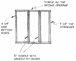
When the 2" is added, the total height of the riser is 8". These risers should be listed as 2 @ 8" x 22 ½”. The 2" piece of plywood is added in order to give the tread a framing member to rest upon. If this were not done, then the rear of the tread below would be supported only by nails driven horizontally through the bottom of the riser on top of it. Many steps are made in that way, but it proves to be an inherently weak structure. The nails easily bend, and the glue bond breaks. The two-inch nailer prevents that from happening.

2 @ 8" x 22 ½”
NAILERS
2 @ 2" x 22 ½”
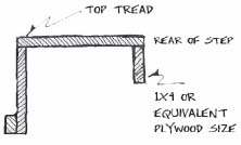
There are some rules with this construction method that make it quite easy to figure a cut list. The first riser piece is always ¾” shorter than the overall height of the rise. All other risers, regardless of how many there are, will be 2"taller than the given riser height. The 2" wide nailers we have been discussing are of course only 22 ½” wide because they fit to the inside of the carriages. The horizontal member at the back of the step unit and which supports the top tread will also be 22 ½” wide, with the other dimension varying depending on the width of the step unit. Very wide steps require a beefier member, but a 3 ½” wide strip should prove sufficient for this small unit. The 3 ½” width was selected because it is the same as the milled width of a 1x4. If there is a supply of 1x4 white pine in the shop, you can substitute it for a plywood version of this part.
REAR SUPPORT
1 @ 3 ½” x 22 ½”
The two carriages are the only remaining items for your cut list. These pieces are not rectangles, but rather a more complex shape. Because of that it is not possible to describe them merely by saying they are “so wide by so long.” Instead you must make a small sketch and dimension the parts.
The section of the carriage that corresponds to the bottom riser is dimensioned at 5 ¼” just as the riser was and for the same reason, that it fits under the tread rather than to the side of it. The next two rises are an even 6" each since they both lose and gain ¾” from their respective treads. The depth of the tread is given at 12 inches. Note that the overall height is 17 ¼”, ¾” smaller than the height of the finished unit.

CARRIAGE DIMENSIONS FOR CUT LIST
CONSTRUCTING THE STEPS
When building steps, it is best to use the table saw to rip the ¾” plywood into strips of the proper width and then use the radial arm saw to cut the strips to length. The project will be more aesthetically pleasing if the grain of the exterior veneer on the plywood runs the length of the pieces. B/C yellow pine plywood and/or ¾” lauan are the best choices of material. C/D is not normally recommended because it is usually too warped and full of voids to fit together well enough to make a good-looking product. Use all of the measuring and marking skills you learned from the chapters on woodworking and flats. This method of construction depends upon a high degree of accuracy from the cutting process, and parts that are not the right size will not fit together well.

FOR BEST RESULTS, RUN GRAIN THE LENGTH OF YOUR PARTS
Since the carriages are not a simple rectangular shape, they require a bit more work to cut out. If the unit is small with only a couple of steps, then it might be best to cut out a rectangle that is the proper overall size, and then to cut a notch to form the required shape. If the step unit is larger, with a number of steps, this might be too wasteful a process. If you are making many units at one time, there will probably be some intuitive manner of laying out the parts that will save on materials. At any rate, mark lines for the parts using the sketch you made as a guide, transferring the measurements and connecting the marks with a straight edge. Use either the bandsaw (if the part will fit) or a jigsaw to cut along the lines, remembering to make the kerf fall on the side of the line that will become scrap.

MAKE THE APPROPRIATE MARKS ON THE PLYWOOD

CONNECT THE DOTS WITH LINES, AND DRAW IN THE PROFILE OF THE CARRIAGE
Assembly can be made easier by following a certain order of work. Connect the 2" wide nailer to the eight-inch wide riser first. If you have used a type of plywood that has one side better than the other such as A/C fir or B/C yellow pine, be sure to keep track of the good and bad sides. Of course you want to put the good face of the plywood to what will become the outside when the project is finished. For the two riser parts, this means attaching the 2" wide strip to the good side of the 8" wide riser, taking care to align it with the bottom and the two sides.
Using a nail gun or a construction stapler will greatly speed up assembly. Naturally, there are a variety of other fasteners that will work just as well, but not as quickly.

ATTACH THE 2" NAILER TO THE GOOD SIDE OF THE RISER
When assembling this sort of work, make sure to use plenty of glue to help adhere the two surfaces. Apply enough so that the surfaces are completely coated. You can learn to gauge this amount by putting on the glue (a zigzag pattern is best), and then pulling the two pieces apart to see if that was enough. Pressing the two pieces together and then squishing slightly from side to side will also help to spread the glue. Use any brand of yellow aliphatic resin (carpenter's) glue. It has very fast bonding properties. However, be aware that once this glue is applied, work must proceed apace as there are really only a few minutes at best before the glue begins to set. If you disturb the glue bond after it has begun to set, the strength of the connection will be greatly reduced.
Finishing nails from a gun do not have a great deal of holding power, so the glue really is essential. It is good to make a habit of gluing together more or less every joint on all projects, unless you know from the outset that they will need to be taken apart at some point in the future. When that is the case, screws or bolts are the preferred fasteners.
Finishing nailers of all brands will typically “set” the nail (or staple) an eighth of an inch or so into the surface of the plywood. Be sure to bear this in mind when selecting the length of fastener to use. For a double layer of ¾” thick plywood a fastener length of 1 ½” is too long. The “set” of the fastener would cause this length to protrude from the back of the underlying piece of plywood. That can lead to some nasty cuts on anyone handling the scenery and looks just awful. Use a slightly shorter 1 ¼” nail instead.
The second phase of assembling the steps is to connect the risers and the carriages. Remember that the carriages will most likely have a good and a bad side, and of course the good side should face outward. It is easiest to stand one of the center risers on end, put glue on the end that is up, and then to lay the carriage on top of the riser. If you nail the center riser first, it is possible to sort of balance the carriage while you go about the business of nailing it. Starting with the end riser will make it very hard to line up the parts. Once a second riser has been attached, the pieces will stand on their own and make it much easier to finish the job. Standing the risers on end will also keep the glue from running off the edge as quickly. Be sure to flush what will become the top of the riser to the top of the carriage, and the face of the riser with the front of the carriage.

TURN THE RISER ON END TO ATTACH THE CARRIAGE TO IT
Once you have completed the task of joining the three risers and the support that goes at the back of the top tread, it is time to flip the unit over and attach the second carriage in the same way. Again, remember that gluing is essential! It is this glue that really holds the wood together. You can view the nails as pins that hold the structure together while the glue sets. Nails don't have much strength at all on their own, but staples are more secure. In keeping with this philosophy, remember that it is not necessary to use absolutely all of the nails in your gun, but rather just enough to hold the pieces in place.
After attaching the second carriage, turn the step unit upright and nail on the treads. Notice that the carriages and risers do not appear to be especially square when you look at them. They most likely are not square at all because we've done nothing so far to make them so. The treads themselves are used to square the unit. Each one should, unless something has gone horribly awry in the cutting process, have four 90-degree angled corners, and two sets of equal sides. This is the ideal shape to use in squaring up a structure.
Put glue on the surfaces that lie underneath the bottom tread, and set the tread into position. Adjust the tread until one of the front corners is perfectly aligned with the corner of the riser and carriage, and put one nail in this corner. Twist the entire step unit until the side of the tread is flush with the carriage, and secure that back corner with a nail. The short side of the tread is connected to the assembly. Now nail the front of the tread, beginning at the first corner you attached and then working your way across to the other side. Aligning two adjacent sides and securing them will automatically square up the entire unit. (Again this presupposes that your cutting was accurate.) This is exactly the same way that a plywood cover is used to square up the framing on a hard cover flat. It is essential to remember to square up the unit as you go along. After the treads are on, it will be too late to affect the squareness of the piece. From here it is a simple matter of nailing the two remaining treads. Remember that a nail every eight inches or so is generally sufficient. Use each one to re-square the unit as you go along.

START IN THE CORNER FLUSH UP TWO ADJACENT SIDES TO SPUARE THE STEP UNIT
HELPFUL HINTS
It is not necessary to align all parts completely before you begin to nail. It is, however, essential to make sure that the point where you are putting a nail is exactly aligned.
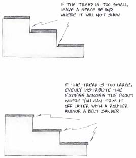
Quite often, the plywood treads will not be an exact fit for the framing structure. There are many reasons for this, with the major one being that plywood is often times slightly thinner than the name would indicate. This is true of most modern plywood and is especially true of sheet goods from the Pacific Rim. They are actually manufactured in metric sizes that are close to the American sizes we use, but not exactly the same. Half-inch is actually 12 mm or approximately 7/16". Three quarters of an inch is actually 16mm or 11/16".
The problem can be addressed by simply allowing the tread to hang over a bit when necessary, and then trimming off the excess with a router and/or belt sander. Leave a space at the back of the tread if it is too small. Just make sure to maintain the same amount of overhang or underhang all the way around to ensure that the piece will still be squared up properly. It is essential that you flush up the first short side completely in order to make the squaring process work.
Nailing the long sides one step at a time from the first corner to the opposite end will remove any bow or curve from the riser piece. The tread will straighten the riser and help to make the entire project appear more orderly.
A stiffener at the bottom of the step unit in the only remaining free corner will help to prevent the plywood from warping inward.

The width of the nailer that holds up the back edge of the treads does not have to be 2". That is simply a number I chose because it is easy to add with other numbers. If you are planning to construct a very wide unit of more than 60 inches or so, increase the size of this member to accommodate the longer span. You can build steps up to 96 inches in width using this method and a 3 1/2" wide nailer. The steps require no center carriage and are completely rigid, with no detectable deflection in the center. Methods that require the use of one or more center carriages are much more difficult to assemble.
ALTERNATE BUILDING TECHNIQUES
Sometimes the design of a stair makes it necessary to use an alternate method of step building. This is often true when the stair as designed has too many steps, or when an “open riser” look is mandated. Some stairs are curved, or at an angle. Some must be made from metal.
There is a fairly simple method that may be used to construct stairs that are larger/taller than the previous method will accommodate. When the carriage involved is larger than will fit on a 4x8 sheet of plywood, it is almost mandatory that this second method be used. Any step unit that rises more than three feet or so in height will be very heavy when constructed with a solid carriage. In this case the open carriage or “stringer” style is much lighter and is generally preferred.

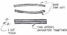
The drawing illustrates the difference between the two types. In reality, the stringer style is constructed in exactly the same manner as the previous demonstration, except for the diagonal nature of the carriage, and the method of marking the notches. This style of carriage is actually somewhat easier to lay out and cut than the closed style. The process is begun by ripping a strip of ¾” plywood for the stringer. If an eight-foot long section of plywood will not be long enough, it is possible to laminate together thinner stock to make up the stringers.

IF YOUR STRINGER PIECE MUST BE LONGER THAN 8'-0", YOU WILL NEED TO LAMINATE IT TOGE THER FROM ¼" THICK PLYWOOD
WHEN LAMINATING PARTS TOGETHER, OFFSET THE JOINTS AS MUCH AS POSSIBLE. PUT GLUE OVER THE ENTIRE SURFACE OF THE JOINT WITH A PAINT BRUSH OR ROLLER.
Be sure to offset the joints in the laminating process to produce a stronger member. For most applications, a 12 inch wide strip of plywood is wide enough for the purpose, although if the stair is to have unusually high rises, deep treads, or a great many steps, it may be necessary to increase the width of the strip to 15 or perhaps 16 inches. It is important that the stringer be large enough to maintain its strength even after the notches have been cut into it.
After the stock for your stringers has been ripped to the proper width, you can mark the location and angle of the notches for the steps. Use a framing square for this job. It is best to use a square that is 16 inches on one side and 24 inches on the other. A speed square will not work. An aluminum square is by far the easiest to use because it is much lighter, and the numbers are easier to read. Remember that with most framing squares, the markings on one side are in twelfths of an inch and in sixteenths of an inch on the other side. The twelfths are used to work on roof pitches and are of little use in scenery building, so you should use the side marked in sixteenths. If you are not sure which is which, count the number of small spaces between the inch marks.

STAIR GAUGES CLAMP ON TO THE SPUARE SO THAT YOU CAN EASILY RETURN TO THE SAME SETTING
Another helpful tool that is an adjunct to the framing square is the stair gauge. Gauges are essentially small clamps that may be fastened to the edge of the framing square. They make it easy to repeatedly find the same spot on your framing square and function as a jig to increase the accuracy of your layout.
Assume that you wish to lay out a set of stairs with a rise of 6 inches and a tread depth of 10 inches. Take the framing square and lay the corner of it across the plywood so that the 6-inch mark on the short side of the square is even with the near edge of the plywood. Rotate the framing square until the 10-inch mark on the long side of the square lines up with the same edge of the plywood strip. If you have a set of stair gauges, attach them to the square so that it is easy to return to the alignment you set up.

Use a pencil to trace around the outside edge of the square to mark one tread depth and one rise. It is best to start at the bottom of the stringer when marking the layout. There is one really tricky part to the process. The bottom riser, as laid out on the stringer, must be shorter in height than the remaining risers by the thickness of the tread, which in our case is ¾”. Use the framing square and measure down from your tread line 5 ¼” in two widely divergent places, making sure that you are measuring at a right angle to the tread line.

MARKING THE BOTTOM OF THE STRINGER
Use the square as a straightedge to draw a line parallel to the original tread line, and that runs through the 5 ¼” marks. You have established the very bottom of the stringer, the part that makes contact with the stage floor.
From this point, it is a fairly simple matter of drawing in as many repetitions of the first riser/tread layout as are required to reach the desired height for the stringer. Remember that as you complete the stringer layout you are looking at it upside down. When the top tread line is marked, you will notice that it is not necessary to mark the corresponding riser line that goes with it. Rather, the line should extend downward from the endpoint to finish off the step.

Construction of this type of step unit is basically the same as our first unit, save for the fact that that the carriage is shaped differently. The riser section sub assemblies are built first, and then attached to one of the stringers. Then the opposite stringer is connected, and finally the treads are used to square the unit. You will need help with these stringers because they are so much bigger and heavier than the carriages in the smaller unit discussed earlier.
At this point you may well wonder how this type of stair remains upright since the carriage does not reach all the way to the floor in the back. One way is too leg the stair so that vertical framing members keep the unit erect. You will need two legs in the back and enough bracing to keep the whole thing together.

LEGS ON A STRINGER TYPE STAIR
Notice the triangles formed by the bracing in the drawing of the freestanding stair on the last page. You can see one large triangle in the side view created by the horizontal rail, the upright member, and the stair itself. In the rear view you can see two triangles that share a hypotenuse. Triangles are a very strong structural form and are often seen in any kind of bracing.
If the stair connects with a sturdy platform, there is a much more elegant solution to the problem. If the platform level is already supported in its own right, it is easy to use that platform to support the stair. If more than one set of stairs is connected to the platform (a front set and escape, for example), the stairs may actually enhance the stability of the platform by acting as diagonal bracing. An excellent method of attaching this type of stair to a platform is to add a section of plywood at the back of the top step that extends upward to the exact height of the platform. This should be an amount equal to the standard height of one of the unit's risers. The strip of plywood will need to be ripped so that it is wide enough to also extend down to the bottom of the framing member that is supporting the back of the top tread. Bolt through this piece of plywood and through the framing of the platform to very securely join the two units. If you fasten the bottom of the stair to the stage floor with a backflap hinge or two, the stair unit itself becomes a piece of diagonal bracing.

NOTE:
THE PLATFORM LEGGING PARTS HAVE NOT BEEN SHOWN IN ORDER TO MAKE IT EASIER TO SEE THE STEP/PLATFORM JUNCTION
Sometimes the design calls for stairs that have open risers, which is to say that the piece that physically makes up the riser itself is left off. These stairs have a more open appearance to them. In this case, the type of all-plywood construction we have been discussing will not work. The 3/4-inch plywood tread is not nearly strong enough to support the weight of a person, even when the steps are very narrow, without being joined with a riser. Therefore a thicker and stronger tread material must be used. Most commonly, two-by lumber of some sort is used, probably a 2x12 or a 2x10, as any narrower dimension would be too small for the tread. This type of stair will also have carriages made from a 2x12, and they must be cut out with the stringer method if the overall height of the stair is more than twelve inches.
When 2x12s are used, the thickness of the treads will be 1 ½” rather than ¾”. As a result, the bottom riser will need to be marked 1 ½” smaller on the bottom of the stringer rather than ¾” as noted in the earlier exercise. This type of stair unit may appear to be airier and lighter to the eye, but it is in reality much, much heavier. It lacks the “portability factor” required by most stage scenery. It will also tend to be less precise, and to warp out of shape more easily, so it is not such a good choice from an engineering standpoint.
It is possible to make this unit entirely from laminated plywood by using three layers of ½” ply on the stringers. You can use a double lamination of ¾” ply for the treads instead of dimension lumber, with the advantage being that the resulting material is more stable. If you glue the plywood together so that only the good side is out, its appearance is enhanced, and any natural bow in the plywood will tend to cancel itself out.
In recent years stair units constructed from steel square tube have become very popular. Indeed, there is much more metal scenery in general because the cost and difficulty of steel or aluminum construction are much less than they once were. One-and-a-half-inch 16ga square tube is a popular choice, but there are many shapes and sizes. Some of these are shown in the chapter on metal working. Steel square tube framing has a very light, open quality that it presents to the audience, which belies the fact that it is in reality far heavier than any other type. However, the unique look of the material has made it a popular choice for designers, especially when the design calls for an industrial look. Although the steel is very heavy, these stairs are not prone to pulling apart from the twisting motion that scenery is often subjected to when it is being moved about.
For steel square tube construction, make a pattern or jig in the shape of a carriage, as discussed earlier. Cut the square tube parts to fit the jig and weld them together. The metal-working chapter goes into detail about how to use wooden blocks to make a temporary jig that will hold the parts in position while they are being welded. After the carriages have been constructed, use straight pieces of tubing to connect the two carriages and form the support for plywood treads.
MAKE A PATTERN FROM SCRAP PLYWOOD AND USE IT TO BUILD A JIG FOR THE SPUARE TUBE STRUCTURE

An alternate method is to form a side runner with a top and bottom chord like a truss. Make the bottom end so that it can mate with the floor at the proper angle. Weld together some rectangular frames that are the proper size for the treads, and connect these in between the two side runners at the proper angle. It is not necessary to weld together the stringer with notches for the rises and treads, as the rectangular tread forms are welded directly to the side of the stringer truss.
