CHAPTER 19
HOW DO YOU MAKE…
This chapter is devoted to explaining the construction of some specific devices that are very commonly encountered in theatrical work. They did not fit into the flow of the other chapters but are important “how to” topics. The projects are not listed in any order and are intended for use as a reference work. Perhaps they will give you ideas for problem-solving devices of your own.

THE DOOR ON THE LEFT WAS MADE BY ADDING PARTS TO A STANDARD HOLLOW-CORE DOOR. THE DOOR TO THE RIGHT IS A FACTORY-MADE, HARDBOARD TYPE. THE FRAME WAS MADE USING THE METHODS IN THIS CHAPTER.
CUE LIGHTS
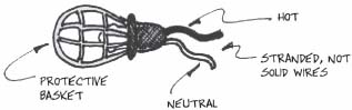
Construction sites often need temporary lighting fixtures that can be tied up around the job. To accommodate this need, manufacturers offer a rubberized, standard screw base socket attached to a basket that is used to protect the bulb in a harsh environment. In years past the baskets were made of metal, but now the yellow plastic type predominates. You can find this product marketed under a names such as “String-O-Lites,” which is actually a quite descriptive title. There is a 50-foot or so run of wire with the sockets spaced along its length. You are really only interested in the sockets, and the roll of wire will not be needed. It is most likely a solid type rather than stranded, and as such is not suited to the requirement of a flexible, portable, cable. You may be able to locate the same rubberized sockets and baskets as separate items, and that will work just fine, too.

THIS IS HOW BASKET LIGHTS ARE INTENDED TO BE USED FOR TEMPORARY LIGHTING. WIRE NUTS ARE NOT SUITABLE FOR EXPOSED WIRING IN A THEATRE
Cut the sockets loose from the wire, leaving at least two or three inches of tail. Since the entire socket assembly is nonconductive, there will most likely be no ground wire, just a hot and a neutral, color-coded black and white respectively.
The wire leads from the socket are connected to the coil of wire with wire nuts or some other kind of mechanical splicer, and you will just have to live with whatever length of lead is provided. If it is less than three inches, you won't be able to connect two of them together, and the usefulness is limited.
Gang two sockets together to make one cue light. Doubling up may prevent some horrible mistake during a performance, for if one of the bulbs should happen to burn out or become disconnected in some way, there will be a second to carry on the fight. That happens much more frequently than you would think and is standard procedure for a commercial touring company. In that profession, the cue lights are sent out as a part of the electrics rental package.
Strip both of the white wires and connect them to the neutral terminal in your connector. Strip both black wires and connect both of them to the hot terminal in your connector. Use a terminal end (spade or ring) when appropriate.
TWIST-LOCK CONNECTOR
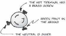
Naturally, different types of connectors are hooked up differently, and you should refer to the manufacturer's instructions for details. In general, however, you will find that most wiring devices use a silver, nickle-plated screw for the neutral terminal and a plain brass screw for the hot terminal.
It is important to keep this procedure straight. The neutral wire should connect with the large metal screw base inside, which is easy to touch by accident. The hot wire should connect to a small conducting plate in the bottom of the fixture, where it is much less likely to cause harm. If you reverse the leads, the opposite will be true, and the risk of electrical shock will be greatly increased.
The 20-amp pin connector is the most common sort of cable end used in the theatre. As far as I know, they are not used by any other field, and are only available from a theatrical supplier. On a grounded pin connector, the pin in the middle is the ground (which you may not need for this project). It is not exactly centered, but rather is a bit to one side. Of the remaining two pins, the one that is the closest to the ground is the neutral. The one that is farthest from the ground is the hot. This selection method works the same for either male or female ends. You need a male end.

PIN CONNECTOR
It is curious to note that before the grounded pin connector was developed, there was no way to ensure that the hot/neutral dedication was preserved. The connector could be turned either way. This was also true of the standard household Edison, or parallel blade plug, before that type was polarized by making the neutral blade wider than the hot blade. Now the off-center placement of the grounding pin makes sure that the hot and neutral wires are connected to the appropriate terminals.
Remember not to strip off too much insulation from the wires. This is probably the most common cause for a short-circuit. Most devices have a chart that tells how much to strip, but a general rule of thumb is to limit this amount to that which will just fit into the terminal or attachment point. Be sure to use whatever strain relief the manufacturer has provided. Some additional wiring tips are available in the chapter on lighting.
It is common practice to use small, round, colored, 7 1/2-watt bulbs in a cue light. Failing this, try using a 15-watt pear shape. Do not use higher wattage bulbs because they will light up the entire backstage, and possibly start a fire when someone carelessly hangs a costume next to the light. Colors become important when more than one cue light is used in the same location (for different cues happening at nearly the same time). If you use these lights often, and move them around a lot (like on a tour), it is often helpful to color code the light and any cable used with it so that it is easier to hook up. Use the same colored tape to mark the switches at the stage manager's desk. Cue lights make excellent circuit test lights, and can also be used as a dancer's spotting light.
STAGE MANAGER'S DESK
On a touring show (and on Broadway), the stage manager's desk is most often the personal property of the production stage manager rather than either the production company or a rental house associated with the show. It might be built by that same stage manager (hmm…), or by some local stagehand, or even a friend. As a result the quality varies greatly, and so does the style. There are, however, some common features that are always found.

STAGE MANAGER'S DESK
The desk is quite literally just that, a desk where the stage manager can sit to call cues. Since many prefer to stand much of the time, it is common to see the desk as a tallish structure using a stool rather than a chair. The top is almost always slanted, and this gives it the appearance of something old Bob Cratchit might have used. There are doors for storage underneath, and it is helpful if this storage area can be secured with a lock. The desk will get moved around a lot, and a nice cabinet lock will be hard to secure if the case gets racked out of shape. They are also much easier to break into. It is common to use a resettable padlock like a Sesame Lock. This way, there are no keys to lose, and the number can be set to an easily recalled combination like your birthday or some historical date. A combination lock can provide access to a larger group of people when necessary. Then you can reset it to a new number when too many people know the old one.
There are some electronic devices that are very often a part of the stage manager's desk. The main station for the headset intercom system is often located here so that the stage manager can easily change channels, volume, etc.
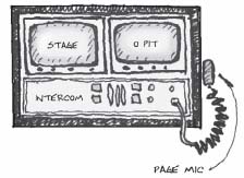
There should be some sort of paging microphone to reach the dressing room monitors for actor's calls. Quite often, you will find a video monitor on top of the desk that gives the cue caller a view of the stage and sometimes a separate view of the conductor in the pit.
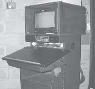
On a tour, these electronics are often supplied by one or more of the rental companies that have been contracted to provide equipment for the show, and they may ride in a separate container, which is then stacked on top of the desk.
One thing that is definitely a part of the desk itself is the bank of cue light switches. It is advisable to have at least five or six of them in order not to run short. They are usually located in a strip above the table surface, below any shelves used for the intercom and/or video/audio monitors.
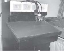
STAGE MANGER'S DESK WITH CUE LIGHT SWITCHES
THE FEMALE TWIST LOCKS ARE OUTPUTS
If the switches are mounted on a removable plate, installation and servicing will be made easier. Outputs should be located on the rear of the desk and can be either panel mount or the pigtail type. Putting the entire desk on casters will make it easy to move around when necessary.
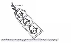
CYC STRETCHING CLAMPS
A sky cyclorama is a 30-foot tall piece of fabric that is as wide as the rigging system will allow. It is difficult to keep this curtain from becoming wrinkled, especially if it has been folded for storage (which is not recommended). A cyc is usually washed with very bright lights in order to create a sky effect. These lights are almost always at a rather oblique angle, one that causes any wrinkles or folds to create un-sightly shadows. As a result, it is often necessary to stretch the cyc out in order to remove the wrinkles. A bottom pipe will stretch out the bottom of the cyc, but something more is required for lateral stretching left and right.

USE THE STRETCHERS TO PULL OUT THE VERITICAL WRINKLES
A series of clamps that can be attached to the sides of the cyc are used with pull lines leading offstage. The clamps should be designed to minimize any damage to the cyc from tearing.

CYC STRETCHING CLAMP
Two, 8"-wide, ¾"-thick plywood blocks can be used for the two sides of the clamp. They will have a better appearance if you dress them up a bit with some chamfering, and it is absolutely necessary to sand all corners and edges in order to avoid ripping the cyc fabric. Two 1/8" thick strips on the clamping side of the jaws will make it easier for the device to get a good bite on the cloth. Drill oversized holes for the quarter-inch bolts that hold the two sides together. The clamp halves will sit at an angle, and the bolt needs extra room to fit loosely. A larger hole on the offstage side provides a point to attach the tying off line.
Use a trucker's hitch to get a nice tight pull on the lines. If you leave a short line with a bowline at the end of it tied to the clamp, you can use the two-line method of the trucker's hitch, and then the clamps can just stay on the cyc even when it is not in use. It will take several clamps on each side to get all of the wrinkles out of the drop.
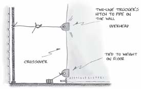
AVOID BLOCKING THE CROSSOVER
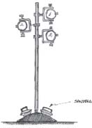
Sometimes it is difficult to find anything to tie off to in the theatre, especially when a crossover is required. On these occasions, tie the bottom clamp off to stage weights on the floor, and the next one over head height. This will allow actors to pass by the ropes. Another method is to lag a lighting tower to the stage at either end of the cyc, and use them as tying off points.

YOU CAN TIE THE LINES TO A TOWER
Lately there is a trend toward using a rear projection screen (RP) and a bounce drop to do the same sort of effect as a sky cyc. It is not advisable to use these stretchers on an RP screen because the material is too delicate. It is generally not necessary anyway.
LIGHTING TOWERS
Lighting towers are the modern equivalent of booms and/or ladders. They use space much more efficiently and are easier to travel, easier to set up, and much safer to use.
The problem with booms is that they tend to be tippy when over a certain height. Hanging an equal number of lights yoked out to either side will help, but the resultant effect is to use up a large amount of valuable wing space. The lights can be hung going onstage and on one side in order to conserve space, but this exacerbates the tipping problem. Most boom bases have no means to lag them to the floor for security, although it is possible to pile on a few sandbags to increase the weight of the base.

EVENLY SPACING THE LAMPS HELPS TO BALANCE THE BOOM, BUT IT IS ALL STILL RATHER CUMBERSOME
Ladders are used on the ends of electrics hanging over the stage. They allow electricians to hang lights downward off the batten, effectively increasing the length of the pipe that is used for side light. Ladders are nice in that the floor under them is kept entirely clear of obstructions, and if your show has a lot of rolling units they may be the best option. Even so, there are some real problems associated with hanging them.
LADDERS ARE A GOOD SOLUTION FOR THE “TIPPY” PROBLEM, BUT MAY CAUSE PROBLEMS IN WEIGHTING THE ARBOR.
LADDERS KEEP THE STAGE FLOOR CLEAR
Many times ladders are several feet taller than the distance from the batten to the floor when it is at its lowest trim. This makes loading the weights a bit of a problem. Either you load the weights with the arbor somewhat low, which may not be possible (and is certainly not safe without taking extra precautions), or you must hang the ladder on the pipe at an angle and somehow straighten everything out as the pipe goes up. Possible, but cumbersome. There really is no elegant solution to that problem other than making sure that the ladders are not too tall for the system. But then they will probably be too short to work effectively.
If your booms are not too tall and there is minimal movement backstage, they will work just fine. If your ladders fit between the pipe and the floor when the batten is all the way in, then they are an excellent means of keeping the floor clear, and it only makes sense to use them.

LADDER FOR 4 LIGHTS
Towers approach the problem from another direction. They are modular units connected together to form a taller structure. Lights fit inside the tower and are thus protected from actors and moving scenery. On a tour, the lights stay inside the towers for the move, just like a rock-and-roll truss. This saves a good deal of time remounting them for each city and reduces time spent focusing. Of course, this approach appeals to anyone's sense of what is neat and tidy, but I also like the way that the towers can be lagged to the floor. When properly done, bolting them to the floor is so secure that there should be no concern that they will tip over. You can never say that about a boom. It is important to use lag bolts that go all the way down into the sub floor so that they get a really good “bite.”

PLAN VIEW
Six feet tall is a good size for a tower section because it is not too hard to move around, and multiples of six just happen to fall at convenient heights. Anything lower than six feet tall is a good height for floor mounts or “shin busters.” Twelve feet is enough overall height much of the time, while eighteen feet is about maximum. Most shows in most houses will trim at somewhere between eighteen and twenty-four feet and it should not be necessary for a lighting tower to go any higher than that. The taller the tower, the more difficult it is to stand up, and the more inherently unstable it will be. You might find that two eight-foot sections are more suitable to your needs. Anything smaller than a six-foot height would seem problematic from the standpoint of being overly complicated to construct.
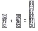
STACK THE TOWER UNITS TO MAKE A TALLER ONE
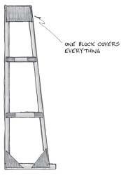
This design for a tower creates a unit that is wide enough for two lights to fit side by side. That will allow you to hang more units right at the top and/or bottom where they are most needed. Provide enough space for the lights to fit in and for the shutters to operate, but keep in mind that it is best to make the tower as thin as possible in order to save on deck space. One saving grace is that given the location of the tower offstage, the focus of the lights is almost always straight ahead and down a bit, so there is no need to leave space for them to turn much to the side. A two-foot square tower is about the right size. You can see how neatly all of these measurements add up for storage.

ONE UNIT OF LIGHTING TOWER
You can also see that this design allows for twelve lights on one-foot centers in each section of tower. On an eighteen-foot tall tower, that means a capacity of thirty-six units per side, for each pair of towers. This should be enough for just about any lighting designer. Of course, most of the time the spaces in the middle are not really used for lighting and can be an excellent location for a sound or video monitor, a fog machine, or some other piece of equipment. All of this and each tower takes up only four square feet of deck space!
Use square tube to construct the tower. (See the chapter on metal frame construction.) It is really just a box with some vertical members connected by horizontals. Make the towers as one solid piece rather than as a series of bolt-together frames. In addition, there are two vertical square tubes that run up the inside back of the tower that are used to connect the lights themselves. It is not necessary to use any C-clamps, just drill a hole in the upright and use ½" bolts that are 2 1/2" long through the square tube and the light yoke. Use washers throughout to make it easier to turn the light when focusing. If you intend to leave the lights in the towers for an extended period, it might be worthwhile to invest in some nylon lock nuts that will keep just the right tension on the bolt and lessen the chance that the nut might vibrate off.

LIGHT BOLTED TO UPRIGHT ON A LIGHTING TOWER
Be sure to provide four holes in the top and bottom of each tower section so that it can be bolted to another section or to the floor. Make the placement of all the holes exactly the same so that each of the sections can fit together interchangeably. This will make assembly easier.
When setting up the show, hang all of the lights in the various tower sections before standing them up. Lay the sections out on the floor, bolt in the lights, and also bolt the sections together in the order they will work. Place the tower so that the bottom section is close to where the tower will eventually live. Use two people to foot the tower, and everyone else in the theatre to walk it up. If there is any doubt about the ability of the hands to control the tower on its way up, use a safety line on the top of the tower. You can use a regular bull line coming down from the grid, rail, or electrics jump. Jockey the tower into final position, and lag it to the floor right away. Make sure that you use bolts which are large enough to hold the tower securely, at least 3/8"x 4".

PUT THE BOTTOM IN PLACE, AND WALK THE TOWER UP
L-JACKS
Jacks are typically used to hold a piece of scenery in an upright position. Most often, they are connected to the back of a column or flat with hinges so that they can be either removed or folded against the unit when not in use.

L-JACK ON A FLAT
You must add weight to the jack in order to stabilize it. A twenty-five pound counterweight placed diagonally between the framing members is great for this purpose. In a TV studio, sandbags are often used.

Another method of stabilizing the jack is to hinge it to the floor. This method has the advantage of being considerably more secure, but it is much more difficult to adjust when necessary, requiring the movement of the hinge. If your scenery must be struck during the show, the simple weight method is probably your best bet unless it is possible to loose pin hinge the jack to a section of decking.
There are two similar styles of wooden L-jacks, and the difference is created mostly by the size of the units involved. The traditional type is characterized by a tall vertical, a shorter horizontal (hence the name), and a connecting diagonal. This works fine in a jack that is ten feet or less in height, but eventually an increasing size dictates a slight change in design.

TRADITIONAL L-JACK
The taller type is truncated at the top, with a number of internal braces, and the resulting structure is somewhat stronger and more rigid. Construction methods are generally the same.
NEW AND IMPROVED L-JACK
It is more efficient to make a number of jacks all at one time. Laying out the diagonal and the cover blocks takes a bit of time, but it is easy to cut out multiples of those pieces. It may take 20 minutes to lay out and build one jack, but only 30 minutes to build two. If you make extra jacks of a commonly used size, you will have some stock units to pull from.
It is easiest to build jacks on a wooden squaring up template table such as was described in the chapter on flat construction. This allows you to quickly form the L corner, and to tack the parts in down on the table, so they are held in place while the blocks are glued and stapled.
USE A TEMPLATE TABLE TO SQUARE THE JACK
A cut list is easily derived. The bottom rail of the jack extends under the stile and the diagonal brace. It is usually in the neighborhood of two and one-half feet in length. Use whatever size base is appropriate to fit in backstage. There is no top rail. The jack should be tall enough to connect with a convenient and logical point on the unit being braced. On a flat, this could mean either the top toggle rail, or perhaps about two thirds of the way up one of the stiles. For a 12'- 0" flat, an eight foot tall brace would need about a two foot rail. When using 1x3 stock that gives you a cut list per unit of 1 @ 7' - 9 1/8" and 1 @ 2'- 0".
The diagonal brace must be scribed from these two members like the method used in full-scale patterns.

Tack the rail and stile into the square corner of the flat frame. Measure down a few inches from the top of the stile, and a few inches in from the end of the rail. Usually, I like to leave a bit more space at the top than at the bottom. This shortens the diagonal a bit, but the real purpose is mostly aesthetic. The jacks just look better that way. Lay a section of stock over the marks and then scribe cut lines on to it. After you have cut the first one and checked it for a proper fit, it can be used as a pattern to cut the rest. This will save a considerable amount of time.
When all of the 1x3 stock has been cut to length, tack down the diagonal for the first jack. A regular corner block can be used for the 90-degree-angle corner. If the other bottom angle is reasonably acute, a regular corner block turned with the hypotenuse down can be marked and trimmed to fit. The grain of the plywood will be at less than a right angle to the joint, but will still be satisfactory. The top intersection of the pine framing is generally too acute to use any stock parts, so plan on cutting these blocks from scratch using scrap ¼" plywood. Run the grain of the plywood horizontally. There is no need to inset these blocks ¾" from the edge of the framing as in a regular softcovered flat, but a ¼" inset will give the unit a nicer appearance.

LEAVE A ¼" SPACE ALONG THE EDGES
This jack has been pictured with the 90-degree-angle corner to the left because that is the most natural way for it to fit on the template. Sometimes, a jack will hinge better if the blocks are on the other side of the unit, especially if the jack is expected to fold back tightly against the flat. It is smart to make some left-handed and some right-handed jacks. The parts are all the same except for the oddly shaped blocks that need to be a mirror image. (Reverse and repeat.) On occasion, you may want to put blocks on both sides when a super heavy-duty jack is required.
STIFFENERS
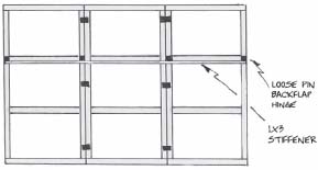
Stiffeners are often used in conjunction with L jacks to provide a wall bracing “system.” The function of a stiffener is to improve rigidity in general and to keep various sections of scenery on the same plane. Stiffeners are not just for walls made of flats, but this type of construction does provide a good example of the principles involved. Information about stiffeners is also available in the section on flats.
Stiffeners are most often wooden and can be as simple as a single length of 1x3 or 1x4. Sometimes, a long wooden stiffener is laminated together from several layers of plywood. This creates a very stable structure. As with any laminated product, be sure to offset the joints and use enough glue to ensure the necessary strength.

STIFFENER PARTS
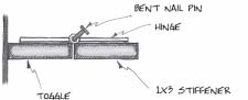
Stiffeners can also be made from a length of square tube with the hinges welded on. The advantage is that the tubing comes in 24-foot lengths and is considerably tougher than wood.
When hinging a stiffener to a group of flats, placement of the hinges is very important. There should be a hinge at the extreme ends and at every joint between the flats. On a softcovered flat, the framing allows for easy connection to the stiles. On a hardcovered flat, that won't work, and it is better to hinge to the tops of the toggles, or perhaps the top rail.
SOFTCOVERED FLAT STIFFENER

HARDCOVERED FLAT STIFFENER
Always locate the hinges on the top of the stiffener so that it does not tend to “flop down” when the scenery is elevated. Maintaining a methodical approach to the framing of the flats during construction makes installation of a stiffener much easier. Perhaps all of the discussion in the chapter on flats about how to properly locate the toggles makes more sense now.
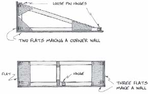
Stiffeners can be used to align flats on more than one plane. Here are a couple of examples of how they can be used to form corners. In this case, more than a simple bar is required. Essentially, a softcovered type of flat is built, but not covered. It is used only for its framing value.
TWO DIFFERENT APPROACHES TO STIFENERS BUILT LIKE FLATS
PLAN VIEWS
Sometimes a stiffener is used to connect oddly shaped profile pieces. Here a tree is used as an example. The central trunk is constructed as one piece, but it would be quite difficult to transport this unit with all of the other limbs attached.

THIS UNIT IS TOO LARGE TO BE ONE PIECE
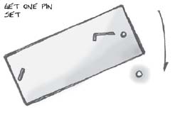
In this case a stiffener is permanently affixed to the small sections, and loose pin hinges are used to fasten the other end to the main trunk. It is often useful to put at least two hinges on one side and one on the other to “trap” the stiffener in place. In addition, small scabs on the back of the added unit are helpful in keeping the pieces from twisting and telegraphing the joint.

SMALL WOODEN SCABS ON THE LIMB KEEP IT ALIGNED WITH THE TRUNK PART
CANE BOLTS
Cane bolts are used to position and secure rolling units to the floor when the action of the play is such that the unit would lurch unpleasantly without them. When viewed from the side, it is easy to see where this item got its name. There are really two parts to a cane bolt, the bolt itself and the sleeve that is used to connect it to the decking unit. The latter is a section of pipe for the bolt to run through, and a welded-on flange with screw holes in it. Cane bolts are commercially available, but in keeping with Murphy's Law, I have found that the flange is almost always the wrong size to fit on my platform, or the bolt is just not quite long enough to reach the stage floor. Making the hardware yourself is not too difficult and ensures a great fit.
It is best to use at least ½" stock for the bolt. This size is hard to bend into the cane shape, but it is also less likely to bend when pressure is applied during the show. If necessary, weld a handle onto the shaft instead of bending. The 3/8" size of bolt may be OK for some lightweight applications, but I have been disappointed by how easily it can be bent. It is always disquieting to sit at a rehearsal and see two actors run across the stage and fling themselves on a bed being held into place by bolts that are too small. Of course in the production meeting the director said it just had to sit there!

SHOP MADE CANE BOLT
If you would like for the bolt to remain with the unit while it rolls, a chain link cut in half and welded into place on one of the flanges can be used for this purpose. Make sure that the bolt is retained high enough to keep from dragging.

CANE BOLT BODY
Sometimes it is possible to just drill through a unit and use that hole as a means of pinning the unit to the floor. This won't work if there is a large gap between the bottom of the unit and the floor because there will be too much play in the assembly.

Grinding the end of the pin so that it is slightly pointy will make it easier to insert it into the deck. Never use more than two bolts, because it will be far too hard to line the piece up, and besides, it is just not necessary. If you concentrate on getting one pin into its hole, it is fairly easy to rotate the unit so that the other simply drops in on its own.
INSERT THE SECOND PIN AND ROTATE THE PIECE UNTIL THE PIN DROPS IN THE HOLE
NOTES ON MOUNTING CASTERS
There are two main types of casters: swivel and rigid. As the names imply, the swivel casters rotate around a vertical axis and can line up with any direction of travel. Rigid casters are fixed, and once bolted to a platform they will allow it to move only back and forth along the same line. Stagehands sometimes call these smart and dumb casters.

RIGID CASTER
At first glance, it would seem that swivel casters would always be more useful than rigid because of their ability to change direction, but this is not necessarily so. The center of the wheel of a swivel caster is offset somewhat from its pivot point on the mounting plate. When in motion, the wheel of the caster follows behind this pivot point, and it is this “drag” principle that causes the caster to rotate in the first place. If the wheel were directly under the pivot point, it would have no reason to turn and align itself with the direction the scenery is moving.
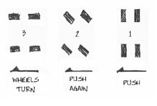
Having said this, it is necessary to apply extra force to the unit to get it to begin moving not only because of the inherent inertia problem, but also because of the necessity of forcing all of the casters to turn and line up with one another. The unit will invariably lurch to the side a bit when this happens, and it is difficult to get it to track straight under some circumstances. This problem can be overcome by lining the unit up offstage, pushing onstage a bit to align the casters, and then leaving it alone until time for the cue. This works fine when going onstage, but there is no way to repeat the process going off. Also, if a unit has four swivel casters, it will often tend to drift to one side or the other, especially if one of the casters becomes hung on something.
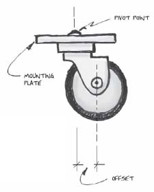
SWIVEL CASTER
If you are sure that a platform will need to move on only one track, all rigid casters can be used. It is important to align the casters with one another and with the unit so that the wheels will turn smoothly without chattering. Use a straightedge to keep the caster plates parallel to one another. Rigid casters are often used with a pallet, especially one meant to be operated with a push stick. (See next section.)

MOUND UNIT
I was once on a tour of Camelot designed to use a large mound unit, on rigid casters, which had to track up-anddownstage at an angle. There was no deck used in the show, and hence no way to use any sort of winch or tracking sys tem. The unit was animated by a large DC motor and a soft rubber tire for traction. After a few trips back and forth, the mound would creep out of alignment. The entire crew would gather around and wrestle it back into place every few performances. Although there were some obvious engineering problems, it worked well enough for the purpose.
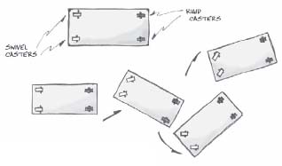
One excellent technique is to mix rigid and swivel casters on the same piece. If you put two rigid casters on the front of the unit, and two swivel casters on the rear, it will steer more or less like a car in reverse. Steering your end to the left will cause the unit to move right, and steering right induces a leftward turn. The advantage is that there is no tendency for the scenery to drift in the wrong direction and one person can easily steer it. The bad side is that just like parallel parking, if you don't hit the mark, you'll just have to back up and try again because there is no way to scoot it over sideways.
USE A MIX OF SWIVEL AND RIGID CASTERS TO MAKE A PIECE EASY TO STEER
Another solution for some units is to use just two rigid casters, placed so that the scenery can be tipped on one side where the wheels are, and then maneuvered like a two-wheeled dolly. Obviously this will only work when the size and weight of the piece are reasonable. One advantage is that there is no need to lock the unit in position. This method works best if the piece in question is between chest high and head high. It is often used on large theatre speakers.

TIP AND ROLL UNIT
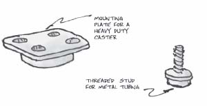
It seems appropriate to spend a moment discussing some of the parts and qualities of casters. Casters used in the theatre almost always have a mounting plate. In contrast, many furniture casters use a spindle that is intended to fit inside a socket, like you would find on a chair leg. These are not very helpful in theatre, because the spindle method of mounting is not really strong enough to hold much weight, although I have on occasion used casters with a bolt or threaded stud connector when joining the caster to a piece of steel square tube.
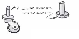
FURNITURE CASTER
In general, the larger the wheel on a caster, the easier it is to roll and the less likely it is to hang up on a rough floor surface. On the other hand, large wheels are harder to get to swivel and change direction. Softer wheels are more difficult to roll than harder ones, but they make less noise. Steel wheels are way too noisy unless you are at a Rolling Stones concert. A high-quality caster rated to carry a lot of weight has a nice set of ball bearings that should be evident when you handle it. If a caster makes a horrible squealing noise when it rolls, then the load is too heavy. Good casters have a load rating that tells you how much weight you can put on them. You should probably order these from a supply house rather than get them at the local hardware store. Good casters are expensive but will pay for themselves over time, especially at a resident company or school.
Always mount casters on the bottom of the framing. If you mount them on the underside of the lid, the framing will become disconnected and fail. If you must caster to the lid on a lightweight piece, take extra steps to ensure that the plywood holds. Use bolts, screws, steel plates, or whatever seems appropriate to beef up the joinery. One good practice when using stock platforms is to run a plate under several of the framing members and then attach the caster to that plate. This method works well when there are several small sections to be ganged together. Just remember that fewer casters will make a sweeter rolling unit, but there must be enough wheels to properly support the structure.

BOTTOM OF A ROLLING UNIT MADE FROM THREE 4X8 PLATFORMS
Sometimes it is possible to use a starter section that has enough casters to stand on its own, and then add on more sections that are supported half by the original section, and half by their own casters. This will drastically reduce the number of casters that must be used. This method works well when the unit must be disassembled for transport.

If you have a large and/or long piece that must move from one level to another (like up a ramp into a truck) it is often helpful to install two rigid casters in the center of the unit to help it over the hump. If these casters are smaller than the regular ones, they will only touch the ground when necessary.

A SMALL CASTER IN THE CENTER OF THE TRUSS MAKES IT EASIER TO GET THE PIECE UP A RAMP
PALLETS
In the theatre, pallets are very low platforms that are used to move scenery on and off stage. Most often, there are one or two pallets on either side of the stage, and they are operated with a push stick to move on and off. When the pallet is pulled offstage, the scenery on top of it (most often furniture or some other prop) can be changed so that a new batch is pushed back onstage the next time. Sometimes the pieces are just laid on top of the pallet, and sometimes it is necessary to fasten them with loose pin hinges. This is a really old-style practice that has been around for a very long time. You can use the same idea for more dimension types of scenery.

TWO PALLETS WITH T HANDLES
The push stick is pinned to the offstage side of the pallet to roll it back and forth. A stick is used so that the stagehand doing the actual work will not be seen. Steel square tube is excellent for this purpose because it is very strong for its size. It is best to paint the stick either black or the color of the deck in order to make it as unobtrusive as possible. A spike mark is set up so that it matches with the end of the handle when the pallet is in place.

WAITING ON A CUE
If a stagehand rolls the pallet onstage to the spike mark, sets the push stick handle on the floor, and then stands on top of it while the scene is played, then the pallet will be in its proper location and stay there. If done properly, the stage-hand will be behind a leg and thus hidden from view. It is difficult to complete a cue like this trailing a headset wire, so it is a good example of a time to use cue lights. A T-handle makes it easier to pull on the pallet and get it to roll back off stage.
Here is an excellent method of making a pallet that I saw once on a touring Broadway show. The unit is built much like a stress skin platform with a top and bottom layer of plywood. Rollers are used rather than casters, because of their lower profile. It is necessary to use quite a few of the rollers in order to disperse the weight of the pallet and its load.

ROLLER PLACEMENT
PALLET WITH ROLLERS
BOXES
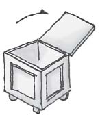
Rolling boxes are used extensively in touring where supplies and equipment must be loaded and unloaded frequently. They are also quite handy to have around a resident theatre to store cable, props, and so forth. They are also great as a work box. Some touring boxes are covered with carpet, or laminate, or have metal edges and complicated latching systems. These are fine boxes, and especially well suited for electronics. They are, however, somewhat difficult to manufacture without investing in a specific technology, and that is not cost effective for small production numbers. There is an older style of wooden box that works just as well and is very easy to build with standard materials in even a very modest shop. This type of box has plywood sides and corners reinforced with 1x4 lumber.
You will need to start by knowing the interior dimensions required by the equipment you will be storing. Cable crates should be no more than waist high, and about 30" square for 20-amp jumpers and somewhat larger for multicable. That stiff, large-diameter cable is harder to coil into a small space. The lid should be hinged to open up and then flop all the way around to the back, out of the way.
CABLE CRATE

TYPICAL PROP BOX
A good size for a prop box is 48" wide by 72" tall and 20" to 24" deep. It is easy to run a show out of this kind of box if it has double doors in the front and a number of shelves inside. After the show, the doors can be locked for security. Casters will allow you to roll the box around as needed.
On a touring production, the studio that builds the scenery and props often constructs this type of wooden case for pieces that are too delicate to travel loose in the truck. These boxes come in all shapes and sizes and often have interior partitions to hold specific items. There is an entire industry devoted to making quite similar crates for trade shows.
Construction is pretty straightforward. Cut slabs of plywood to size for the bottom sides and top. Use ¾" ply for the bottom, and ½" for everything else. Make sure to adjust your cut list to account for the thickness of the plywood where it overlaps. (See the chapters on construction.) Don't worry about lids or doors yet; it will be easier to figure them out after the body, or case, is done. Glue and nail/staple the plywood body parts together. Make sure that the sides sit on top of the ¾" plywood bottom. This will make for a stronger structure when the strapping goes on and casters are attached.

The 1x4 strips will reinforce all of the edges and corners. Wherever possible, the overlap of the lumber should be the opposite of the overlap of the plywood. This will give the strapping a better purchase on the plywood. Use plenty of glue, and staple from the inside, through the plywood and into the 1x4 whenever possible. Use fasteners on the outside to join the corners of the lumber.
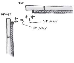
In order to make a door or lid fit properly, extend the 1x4 lumber ½" past the edge of the plywood edge where the lid will fit. Cut the plywood for the lid so that it fits loosely inside the strapping but on the plywood edges of the case. Align the edges of the strapping for the lid with the outside edges of the case strapping. In this way, the lid is interlocked in position when closed, but the outside of the case will be smooth.
OVERLAP THE PARTS THIS WAY SO THE BOX WILL NOT GET TWEAKED OUT OF SQUARE WHILE MOVING.
Use a router with a ¼" rounding over bit to ease all of the corners of the box, inside the strapping and out. Not only will this prevent your hands from getting splinters later on, it will also make the box last longer by preventing large cracks from developing in the strapping.

Interior dividers and shelves can be held in place with cleats, glued and screwed to the inside walls. It is generally not a good idea to set the shelf into a dado groove because there is too much movement in the casework, and the shelf will tend to pop out.
Be sure to bolt the casters on the bottom to ensure that they will stay attached. T-nuts are useful for this, because they keep the bolt end from sticking out and catching on things. A cable crate may weigh hundreds of pounds when fully loaded, so bear this in mind when selecting casters. Use large strap hinges for the doors, and bolt these on also. A hasp should be provided to secure the lid, and if necessary, a padlock for security. If security is not a problem, a short length of sash cord can be stapled to the box, and the end run through the hasp to keep it shut.
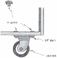
T NUTS LEAVE THE INSIDE OF THE BOX CLEAR. DRILL A LARGER HOLE SO THE THE SHAFT OF THE NUT WILL FIT.
Metal corners can be screwed on to beef up the strength of the wooden corners of the box. There are many types of these; just pick something big enough to really do some good. Finally, a good coat of waterproof paint will help to protect the box from rain and from scraping up against other objects.
LAMP RACKS
Lamp racks are used to store lights and other equipment when it is not in use. A touring rig uses lamp racks specifically designed to:
A) hold lamp bars made of unistrut with several fixtures on it, and
B) fit into a tractor trailer truck.
This makes for some fairly specific requirements, and the racks tend to be quite large. In a resident theatre, a lamp rack will probably hold only single instruments with C-clamps. The overall size may be dictated by what will fit in an elevator or through a door, and you should investigate these parameters for your particular venue. I have found that a rack that is 72" long, 60" tall (excluding casters), and 18" wide will hold most kinds of fixtures and will fit almost anywhere.
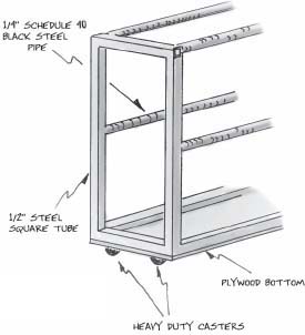
LAMP RACK
Lighting C-clamps are intended to fit on a round pipe. Pipe is somewhat difficult to weld together at an angle and is very heavy. Square tube is much easier to work with, but the C-clamps will not fit on it, so a compromise is in order. An excellent rack can be made by using square tubing for the end frames and black steel pipe for the connecting pipes. Either 1 ¼" or 1 ½" pipe will work. If you select the same size used in your theatre for the electric hanging positions, it will make it easier to run the C-clamp bolt when moving the lights back and forth.

It is a good idea to provide a plywood bottom to the rack for gel frames and barn doors and the like. You may wish to use two swivel and two rigid casters if the racks must travel long distances with one person pushing them. If they must be maneuvered through tight spaces, four swivel casters will probably work better.
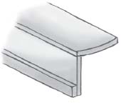
PINCH CLEATS
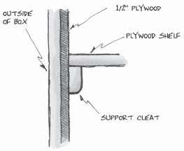
Pinch cleats are used to easily attach a cabinet or awning or similar object to a wall surface. The wall must be rigid for this technique to work. For instance, a softcovered flat is generally not acceptable unless it has been specially framed to accommodate the cleat.
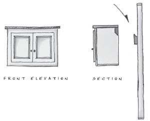
HANG THE CABINET ON THE WALL USING A PINCH CLEAT, SO THAT IT IS EASILY REMOVED.
THE OPPOSING ANGLES DRAW THE TWO HALVES OF THE CLEAT TOGETHER.
The basic principle involved is to lock together two boards cut at an angle. The piece will be hung securely from the top, as long as no one pushes up on it and disengages the cleat. When hanging, the bottom of the cabinet will press hard against the wall, which is why the hanging surface must be sturdy and rigid. There are lots of fun ways to use this technique on different types of scenery. It is great for quick assemblies.

CLOSE UP VIEW OF HOW PARTS FIT TOGETHER
CIRCULAR SAW GUIDE
Most of the time you can free-hand with a circular saw, but on occasion it is nice to be able to work with more precision. In that case, you can use this shop-made guide to ensure a straight cut. Make exact cuts by lining up the edge of the guide with the line you would like to cut.
The jig is very simple to make from a couple of strips of plywood. After assembly, run the saw down the channel and trim off the edge of the guide so that it is exactly the width of the saw table.

USE TWO STRIPS OF PLYWOOD TO MAKE A CIRCULAR SAW GUIDE
The kerf will fall to the outside of the guide, so it is generally best to line the jig up so that it is on top of the piece you will be keeping.

The guide must be firmly secured to the work. You can do this by clamping it down or by using drywall screws. The clamps are sometimes problematic when the saw motor doesn't have enough clearance to move over the tops of the clamps.
Make sure that the left side of the saw table stays securely against the thick part of the guide in order to make a straight cut. With a little practice, you can “plunge” the blade into the work in the middle of the plywood rather than starting from the edge. This will allow you to cut square holes in the center of a sheet of plywood or other shapes that do not continue all the way to the side of the sheet.

USE THE SAW GUIDE TO CUT INSIDE CORNERS BY “PLUNGING” THE SAW BLADE INTO THE WORK
You will need to have a different guide for each saw if the distance from the blade to the side of the table is not the same. Rotating the saw to an angle will make the guide just a bit smaller when you go to use it on a ninety-degree cut. You can make similar guides to use with a router. That will allow you to make really straight dado cuts with a straight-edged trimming bit.
BACKSTAGE HANDRAILS
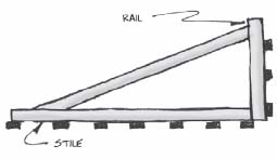
Here is an easy way to make traditional-style handrails for escape stairs and other elevated structures. The uprights and the actual rails (notice that the horizontal part is called a rail) are both made from 1x4 stock, something that is commonly found in most shops. This particular style is designed to be removable and reusable. That is convenient if the scenery must be struck and reassembled, and/or if you would like a stock of parts to use with different shows.
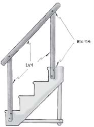
THIS HANDRAIL CAN BE EASILY REMOVED
It is important to ease the corners of the 1x4 to prevent splintering. The ends have also been chamfered to make them easier to use and to improve their appearance.

HANDRAIL PARTS
Bolts are used to attach the stiles to platforming and stairs, but you can also use drywall screws for the same purpose. If the stairs are to be struck and reassembled frequently, it makes much more sense to use bolts, but if there will be only one setup, it might be kinder to other stock units just to screw the parts on. Be aware that screws do not hold nearly as well as the bolts. If you have any doubts about the soundness of the structure, use the bolts.
Note that two bolts are used to secure the stile to the steps or platform. This will keep the uprights rigidly plumb. A block of wood is also attached to the upright stile to keep it rigid, and that makes it easy to make it just the right height as well.
At the same time, only one bolt is used in the top of the stile. That will allow the rail to be attached at an angle. If you are striking the show with the intention of putting it back up, you can leave the stiles and rail bolted together in one piece. Take out the bottom bolts, and fold up the rest of the hand rail into one convenient unit.

FOLDS UP FOR EASY STORAGE
CURVED STAIRS
True circular or spiral stairs have a center post or column. In a steel or cast iron example, the treads are cantilevered out from the center pipe and are kept in place with a spiral handrail. It is certainly possible to weld together that sort of structure from steel pipe and plate, but you would most likely be better off with a factory made version or something from architectural salvage. Curved stairs are something else. They are quite often much wider than a spiral stair, and the bottom carriages are boxed in. Actually, this method will work with any odd shape, not just a circular curve.
This method of constructing curved stairs is similar to the one shown for rectilinear stairs in Chapter 13. It features all plywood construction and uses nailing strips on the risers. It uses many of the techniques associated with full-scale patterns. You may wish to refer back to those topics if you are unsure of the techniques shown here.

SPIRAL STAIR
CURVED STAIR
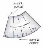
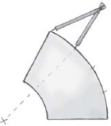
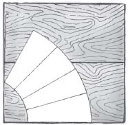
Begin by laying out a full-scale pattern of the stairs you wish to make. You can do this on paper and transfer the pattern to wood, or just lay out the whole assembly on ¾" plywood from the outset. Use trammel points to mark the inner and outer diameters. The treads may not be dimensioned on the plans. Even if they, are it is generally more accurate to mark the outside profile of the unit and then divide the space up into the correct number of treads. Be sure to clearly mark the center point of the two arcs you made in originally laying out the curves. That is the convergence point of all the lines you will be marking for the treads, althought the treads do not extend that far.

YOU WILL NEED THESE DIMENSIONS
You can use a bow compass and the trial-and-error method to divide the outer arc into the desired number of parts. Set the compass to a trial size and divide the arc into segments. There will be some amount of error at the end of the process. “Guesstimate” your correction by dividing the error amount by the number of segments. You should be able to determine a reasonably accurate layout within three or four tries.
USE A COMPASS TO DIVIDE THE STAIR INTO EQUAL SEGMENTS
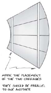
Mark straight lines across the arcs as shown in the diagram. These two lines delineate the locations of the two carriages. The exact placement is somewhat arbitrary, but pick a spot reasonably close to the edge of the stair. The carriages must be parallel to one another. Mark another pair of lines ¾" to the inside of the original ones. This space represents the location of the ¾" ply used to form the carriages.
Use this pattern to lay out the size and shape of the two carriages. They will not be the same, since they intersect the diverging rays at different distances from the center point. You will be making straight carriages to fit against round steps. You will need to cut angles for each place where the carriage and riser intersect. The angles will be different from step to step, but the same angles will transfer to the second carriage if the carriages are parallel to one another.
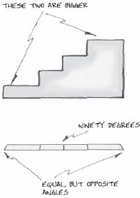
Tread depths will vary because of the way the lines run across the steps, so you will have to measure each one separately. This is the difficult part about this method, measuring and transferring all of the angles and sizes. It will take the most time, but it is important to get a good fit. Use an adjustable jigsaw or circular saw to cut the angles needed for the vertical cuts. All of the horizontal cuts will be ninety degree angles.
Cut out the treads from the pattern. This would be a great time to use the saw guide jig shown a few pages back. Notice that there will be some loss of tread size, because of the kerf created by the saw blade, if you cut directly from a ¾" plywood pattern. You can do that if the unit is very small, but a large one will not fit on the 4x8 sheets very well. Cutting directly from the pattern will cause the treads to be a tiny bit too small, but the discrepancy will not usually be a problem. If you you are making a very large number of these units, it might be worthwhile to mark paper patterns and get the sizes exactly right. Most of the time you can simply hide the loss as a small gap to the rear of the tread.
CUT OUT THE FIRST TREAD AND USE IT AS A PATTERN TO AVOID HAVING TREADS IN TWO PARTS
Measure the distance from the inner arc to the outer arc to get the length of the riser parts. This is also the same as the length of the treads. The risers will go all the way from side to side because there are no carriages to fit inside of. Instead, the risers will be trimmed to fit on top of the carriages. The ends of the risers are 90-degree angles. Make the bottom of the carriages ¾" short on the first tread to allow the bottom riser to fit to the front of the carriage.

THE BOTTOM RISER INTERSECTS IN THIS MANNER
Connect a 2" nailer to the front of each riser. Place each riser on top of the pattern and mark where it hits the carriage. You will need to cut a notch through the 2" nailer and bottom of the riser so that the riser will set on the carriage with the nailer sticking down and the top of the riser even with the top of the carriage. You can cut this slot at an angle if that is easy for you to do, but really it is only necessary to cut the slot wide enough to account for the thickness of the material at an angle.
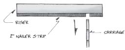
CUT A NOTCH IN THE RISER SO THAT IT WILL FIT DOWN ONTO THE CARRIAGE
When all of the notches are cut, assemble the treads and risers into 90-degree angle units. It is very different from the technique used with rectilinear stairs. This is due to the fact that it is difficult to line up the risers and carriages in the same way as a normal stair since there are odd angles and shapes involved. It is more accurate to line up the riser of one step with the tread of the next to get the closest fit. If you have a pattern marked on paper, or on the floor, you can use that to help judge the best alignment. In any case, be sure to lay all the pieces out together and check the fit before you begin to assemble.
ASSEMBLE THE TREADS AND RISERS FIRST, THEN ADD THEM TO THE CARRIAGES
There is one other piece to take into consideration before you begin the assembly. This is a curved piece used at the bottom to help in putting a facing on the unit. You may need one for each of the curved sides, or if one faces upstage, just the side that faces the audience. The facings do not have much of a structural function and are really just decorative.
It is best to mark these pieces at the same time as you are laying out the original pattern. Lay a section of plywood so that one edge is against the outer mark of the carriage. Use the compass to mark the same curve as will be to the outside of the stair. Cut out this piece so that one side is the arc, and the other a straight line.

Attach this section to the bottom of the carriage, the bottom of the lowest riser, and any support pieces to the rear of the unit. If the stair is large, you may wish to add some uprights between some of the treads and the bottom curve in order to have more support for the sides. Use 1/8" bending plywood to cover the curved sides. It is easier to cut the shape of the risers/treads somewhat big and to trim to the exact size with a flush trim router after the facing has been put on.
If you need a unit with more than five or six treads, consider making it in more than one piece. The curve of the treads on anything larger will probably be too tight for the straight line carriage, and/or the unit will be very heavy.
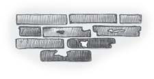
FOAM RUBBER BRICKS
You may often be called upon to create three-dimensional bricks for a wall. Here is a way of doing that with the sort of foam rubber that is used for sofa cushions. It is readily available at fabric stores. This foam product is made from latex and is very different from the polystyrene products mentioned in the chapter on working with foam. It is much more bendable. If you have a choice, be sure to select the densest foam available. It is more expensive, but it is much easier to work with. To make bricks, you should purchase foam that is about 2" thick, since this is about the height dimension of a standard brick. If you are making a stone wall, or some other specific texture, you may wish to select a size that is more appropriate to that project. You will eventually be slicing the foam into pieces that are only 1/8" or so in thickness.
You can get an insight into making stage brick texture by looking at real brick walls. Notice that the bricks do not stick out very far past the mortar. In fact, most of the time they hardly stick out at all. On an older structure, the edges of the brick have been softened by time and indeed the entire brick may have small pieces flaked off and other imperfections. It can be difficult to reproduce these features using rigid materials. The foam rubber is really effective because it is so soft and pliable.
The difficult part of the process is slicing the foam into thin sections. If you do a lot of this work, you may wish to invest in special tools used by upholstery shops to cut and shape foam rubber. They use a blade that may well remind you of an electric carving knife, and indeed you can also use one of those to cut foam. However, they do not have the power or industrial strength of the real thing.
You can also use a bandsaw to do the cutting. The bandsaw will not make nearly so smooth a cut, but since the bricks look better with a slightly rough texture, that is not generally a problem. You must have a rip fence on the saw in order to make this work. If your saw does not have a rip fence, you can clamp two boards at an angle to the top of the table as a shop-built version. Any type of fence will work better if you wax the face so that it becomes really smooth and creates less drag on the foam. The foam itself is very compressible and difficult to cut on the saw. There is a tendency for the material to bunch up and get drawn through the table of the bandsaw. Don't even think about cutting foam rubber with any sort of circular saw. That will not work.
There are some other techniques that can help in cutting the foam, considering that you want to have very thin slices of the foam to work with. Set the bandsaw fence at about 1/8" to a ¼" from the blade. This is somewhat variable. If the foam is really dense, you can get away with the thinner size. If the foam is very light, you will most likely not be able to run it that thin. You only need a very thin slice to create the texture of the brick, and thinner slices use less of the material and are easier to work with.
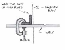
CONNECT TWO BOARDS AT A 90 DEGREE ANGLE. CLAMP TO TABLE TO MAKE A RIP FENCE.
It is important to pull the foam through the saw, rather than to try to push it through. If you push on the foam it will simply bunch up and jam the saw. Pulling will help to keep that from happening. Be sure to wax the guide or fence. Use a piece of wood as a guide to keep the foam pressed against the fence as you pull on it. That takes two people. You will need to practice a few runs to get the feel of what the best feed rate is and how much pressure to use in holding the foam against the fence. At some point, the piece of foam you are cutting from will become too small to work with and will bunch up around the blade no matter how careful you are. If that leftover is reasonably thin, you may still be able to use it. Put some tape over the throat plate that covers the hole where the blade dissapears into the table to make it smaller.

When the ripping/slicing work is done you will have lots of thin strips of foam. Some of them will be very clean, and some will have a more textural appearance. This is actually a good thing, because it will make for a more varied appearance to the wall. Use a pair of scissors to cut the strips to the proper length, which for most bricks will be about 8" or so. You will need some half bricks, and perhaps some that are odd shapes around windows and such. These are all easily cut with the scissors. Consult the plans or rendering to determine how the bricks are to be applied.

Use a chalk line to strike even lines across the surface so that you have reference points to work from. You may wish to use the more indelible red chalk for this project. If there are brick features like windows, or coins, or some other irregularly shaped areas, lay them out first.

Apply the foam using regular white or yellow glue. The yellow will set up faster, so pick the kind that is compatible with your working speed. Of course if the glue dries before you apply the foam, you can always just put more on. If you are working on a large flat surface, use a roller to apply the glue. Use a fairly thick coat of full-strength glue. Press the foam bricks down into the glue so that they are firmly attached. This process can move ahead fairly quickly on a flat wall. If you have pieces of varying thickness, try to get as random a pattern as possible There will be some pieces with torn holes, and/or extra blobs of foam on them. These are actually the ones that will make the project look really good when it is finished. Sometimes you can bend the pieces around a corner, but most of the time it makes more sense to use two separate sections. Especially since a corner normally reveals an 8" section of one side of a brick, and the 4" length of its end.
MISSHAPEN BRICKS ARE OFTEN THE BEST ONES. SPACE THEM OUT RANDOMLY.
Let the glue set up until it is really dry. Check the wall for parts that did not get stuck well, and reattach them with a small bottle of glue. You may need to use the scissors to do some last minute trimming of parts that stick out too much.
The foam needs some kind of sealer to look good. Actually, the more sealer you glop on, the better the brick will look. Used by itself, the foam will soak up too much paint and will have an odd, spongy appearance. The sealer will cover the seams between parts of bricks and make the mortar lines more realistic looking. There are actually several things that you can use for this process.
One is a type of scenic dope made from drywall mud and glue. Mix the two together with enough water to make it workable. Joint compound is very cheap and this material is very easy to apply. The only problem with it is that it is also somewhat brittle and tends to chip off. Also, it completely wipes out any compressiblity that may be gained from using foam rubber to make the original shapes. If you are fitting together various parts of a wall, the fact that the foam can be compressed as the parts fit together can be a big plus in acheiving a good fit. If these factors are not an issue, the scenic dope approach will work well.
Sculpt or Coat is a brand-name product available from theatrical suppliers. It will create a heavy, latex-like coat on the surface of the foam. It is very pliable, much like the foam rubber itself. This product is very viscous, and when slathered on in large amounts will do a great job of filling joints and creating a generally rounded over, well worn sort of appearance. It will not greatly affect the “compressibility” of the foam.
There are various generic brands of roofing material that are meant to be used in repairing leaky asphalt shingles. They can be found at home centers in the roofing material section. They too have a thick, highly viscous nature. It is very important to select a product that is water-based. If it is flammable, it is not a water-based product. Often you may find some versions that are thicker than others, and it is generally best to use the thickest version.

YOU CAN GET ROOF SEALERS IN ONE, OR FIVE GALLON CANS THEY ARE RELATIVELY CHEAP.
These coatings are very messy, and they are difficult to remove from adjacent surfaces. You should experiment, but it is generally best to use several coats for the best effect. Lay the scenery out so that the pieces are abutting one another to apply the coating to ensure a uniform appearance, but separate them before the material begins to harden. It may take quite a while for that to happen.