Chapter 2
HyperFlex Architecture
The Cisco HyperFlex HX Data Platform is a high-performance, distributed file system that supports multiple hypervisors with a wide range of enterprise-grade data management and optimization services. The Cisco HyperFlex HX Data Platform combines the cluster’s storage devices into a single distributed, multitier, object-based datastore. It makes this data available through the file system protocols and mechanisms needed by the higher-level hypervisors, virtual machines, and containers. Performance scales linearly as a cluster scales because all components contribute both processing and storage capacity to the cluster. A Cisco HyperFlex cluster can be deployed in three different ways:
HyperFlex standard cluster: This type of cluster is composed of a pair of Cisco UCS fabric interconnects and at least three HX hyperconverged nodes.
HyperFlex stretch cluster: With a stretch cluster, half of the cluster nodes are physically located in one place, and the remaining half are located in a distant secondary location.
HyperFlex edge cluster: This type of cluster is composed of at least three HX hyperconverged nodes, with no UCS fabric interconnect required. Starting with HyperFlex version 4.0, it is possible to deploy cluster with only two HX hyperconverged nodes.
Figure 2-1 illustrates a Cisco HyperFlex solution.
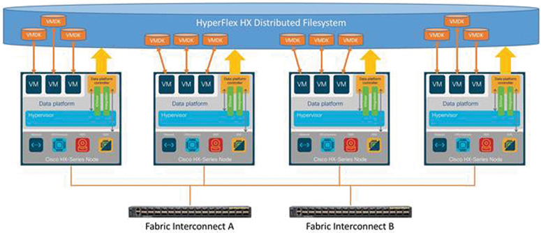
Figure 2-1 Cisco HyperFlex Solution
HyperFlex Architecture Components
This section covers the components that comprise the HyperFlex architecture.
Storage Controller Virtual Machine
The HyperFlex architecture requires a storage controller virtual machine (SCVM) with a dedicated number of processor cores and amount of memory—enough to allow the SCVM to deliver consistent performance and not affect the performance of the other virtual machines on the cluster. The controller can access all storage without hypervisor intervention, thanks to the VMware VM_DIRECT_PATH feature. It uses the node’s memory and SSDs as part of a distributed caching layer, and it uses the node’s HDDs for distributed capacity storage.
The controller integrates the data platform into the VMware vSphere cluster through the use of three preinstalled VMware ESXi vSphere Installation Bundles (VIBs) on each node:
IO Visor: This VIB provides a network file system (NFS) mount point so that the ESXi hypervisor can access the virtual disks that are attached to individual virtual machines. From the hypervisor’s perspective, it is simply attached to a network file system. The IO Visor intercepts guest VM IO traffic and intelligently redirects it to the HyperFlex SCVMs.
VMware API for Array Integration (VAAI): This storage offload API allows vSphere to request advanced file system operations such as snapshots and cloning. The controller implements these operations via manipulation of the file system metadata rather than actual data copying, providing rapid response and thus rapid deployment of new environments.
stHypervisorSvc: This VIB adds enhancements and features needed for HyperFlex data protection and VM replication.
A HyperFlex cluster requires a minimum of three HX-Series “converged” nodes (with disk storage). Data is replicated across at least two of these nodes, and a third node is required for continuous operation in the event of a single node failure. Each node that has disk storage is equipped with at least one high-performance SSD for data caching and rapid acknowledgment of write requests. Each node also is equipped with additional disks, up to the platform’s physical limit, for long-term storage and capacity.
HX Services
Each SCVM running on the hyper-converged nodes runs an instance of the Linux services used by the HyperFlex system. Table 2-1 lists these services and their purposes.
Table 2-1 HyperFlex Controller Services
HX Service Name |
Linux Service Name |
What the Service Does |
Springpath file system |
storfs |
Core of the Springpath file system. Owns disks and read/write process |
SCVM client |
scvmclient |
Proxy NFS server running on ESXi that intercepts the file I/O operations and sends them to CRM |
System management service |
stMgr |
Overall system management and inter-process communication |
HyperFlex Connect server |
hxmanager |
HX Connect UI Manager Service |
Replication services |
replsvc |
Responsible for replication |
Cluster IP Monitor |
cip-monitor |
Responsible for assigning cluster management and data IP addresses |
Replication Cluster IP Monitor |
repl-cip-monitor |
Responsible for assigning cluster replication IP addresses |
Stats Cache Service |
carbon-cache |
Accepts metrics over various protocols and writes them to disk as efficiently as possible; requires caching metric values in RAM as they are received and flushing them to disk on an interval using the underlying Whisper library |
Stats Aggregator Service |
carbon-aggregator |
Can be run in front of carbon-cache to buffer metrics over time before reporting them to Whisper |
Stats Listener Service |
statsd |
A network daemon that runs on the Node.js platform and listens for statistics, such as counters and timers, sent over UDP or TCP and sends aggregates to one or more pluggable back-end services (such as Graphite) |
Cluster Manager Service |
exhibitor |
Controls stop/start and configuration of Zookeeper |
HX Device Connector |
hx_device_connector |
Responsible for connecting to Intersight |
Web server |
tomcat |
Web server using Java servlets |
Reverse proxy server |
nginx |
HTTP and reverse proxy server, as well as a mail proxy server |
Job scheduler |
cron |
Daemon to execute scheduled commands |
DNS and name server service |
resolvconf |
A simple database for runtime nameserver information and a simple framework for notifying applications of changes in that information |
Stats web server |
graphite |
A web application that uses the Twisted framework to provide real-time visualization and storage of numeric time-series data with a daemon that processes the incoming time-series data and saves it as Whisper database files |
Cluster Management IP |
mgmtip |
The cluster management IP service in pre-3.0 clusters |
IO Visor
IO Visor, which is the SCVM client, lives as a process in user space inside ESXi and can be thought of as a simple NFS proxy. It behaves as a server for the VMware NFS client, while looking like a client to the controller VMs (stCtlVM/SCVM server). It is installed into ESXi as a vSphere Installation Bundle (VIB) that is auto-deployed during cluster installation.
Log Structure File System
The data platform implements a log-structured file system that uses a caching layer in SSDs to accelerate read requests and write replies, and a persistence layer implemented with HDD data distribution. Incoming data is distributed across all nodes in the cluster to optimize performance using the caching tier. Efficient data distribution is achieved by mapping received data to stripe units that are stored equally across all nodes, with the number of data replicas determined by the policies you set.
Figure 2-2 illustrates a logical representation for the Log file system.
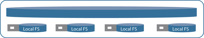
Figure 2-2 Log File System
Data Optimization
Overall space consumption in the HyperFlex clustered file system is optimized by the default deduplication and compression features.
Deduplication is always on, helping reduce storage requirements in virtualization clusters in which multiple operating system instances in guest virtual machines result in large amounts of replicated data.
Compression further reduces storage requirements, reducing costs. In addition, the log-structured file system is designed to store variable-sized blocks, reducing internal fragmentation.
Figure 2-3 provides a logical representation of the inline compression and deduplication of the HyperFlex system.

Figure 2-3 Inline Compression and Deduplication
HyperFlex Cleaner
When exiting data gets updated, it gets appended to the log, and the metadata tree also gets updated. When this happens, the original blocks of data are left behind, with no references that need to be garbage collected. Likewise, when a file is deleted, the segments that make up the file are still persisted on the disk as dead keys until the cleaner runs and compacts the segment to free up space.
Figure 2-4 provides a logical representation of the data blocks when they get updated or deleted.
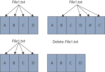
Figure 2-4 HyperFlex Updated and Deleted Data
Cluster Resource Manager (CRM)
Cluster Resource Manager (CRM) has many responsibilities as it coordinates functions across a cluster. It is responsible for understanding all resources available in the cluster. In addition, CRM is responsible for the timely detection of failures and conducting the appropriate remediation.
CRM maintains a Zookeeper (ZK) database that is responsible for mapping data to the mirror set.
Cleaner removes stale data and releases storage. It typically runs in the background continuously. Cleaner goes into sleep mode when it is not needed and wakes when policy defined conditions are met.
A cluster shutdown stops storage cluster operations and shuts it down. A shutdown cluster has all storage cluster processes, including the working VMs, powered down. This does not include powering down the nodes in the cluster or shutting down the vCenter or FI cluster. The Cisco HX cluster shutdown procedure does not shut down the ESXi hosts.
Rebalancing occurs when a CRM event is triggered, such as when resources are added (either a new node, a new disk, or both), resources are deleted (retiring a node or a failure condition), monitoring timers are expired, or users initiate requests.
Zookeeper
Zookeeper is a service for maintaining configuration information, naming information, distributed synchronization, and group services for distributed applications within a cluster. It allows distributed processes to coordinate with each other via a shared hierarchical namespace, organized much like a file system, where each node in the tree is known as a znode.
Zookeeper also provides high availability and reliability, with no single point of failure characteristics for large distributed environments. It is replicated over a number of nodes called an ensemble. The nodes in the ensemble must know about each other in order to maintain an image of state and transactional logs.
HyperFlex HX-Series Node Overview
The Cisco HyperFlex solution is composed of three different types of nodes:
HyperFlex hybrid nodes: Hybrid converged nodes use a combination of SSD for the short-term storage caching layer and HDDs.
HyperFlex all flash nodes: An all flash converged node uses only SSDs.
HyperFlex edge for remote branch offices: Hybrid or all flash converged nodes based on the HX220c.
Figure 2-5 illustrates the different HyperFlex node models.
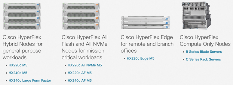
Figure 2-5 Cisco HyperFlex Models
HX220 M5/M4 Series
The HX220c M5/M4 servers extend the capabilities of the Cisco HyperFlex portfolio in a 1U form factor with the addition of the Intel Xeon processor scalable family with 24 DIMM slots.
HXAF220c-M5SX All Flash
HXAF220c-M5SX All Flash is a small-footprint Cisco HyperFlex All Flash model that contains a 240 GB M.2 form factor SSD that acts as the boot drive, a 240 GB housekeeping SSD, either a single 375 GB Optane NVMe SSD or a 1.6 TB NVMe SSD or a 400 GB SAS SSD write-log drive, and six to eight 960 GB or 3.8 TB SATA SSDs for storage capacity. For configurations requiring self-encrypting drives, the caching SSD is replaced with an 800 GB SAS SED SSD, and the capacity disks are also replaced with either 800 GB, 960 GB, or 3.8 TB SED SSDs.
Figure 2-6 shows the front view of an HXAF220c-M5SX All Flash node.

Figure 2-6 HXAF220c-M5SX All Flash
HX220c-M5SX Hybrid
HX220c-M5SX Hybrid is a small-footprint Cisco HyperFlex hybrid model that contains a minimum of six and up to eight 1.8 TB or 1.2 TB SAS HDDs that contribute to cluster storage capacity, a 240 GB SSD housekeeping drive, a 480 GB or 800 GB SSD caching drive, and a 240 GB M.2 form factor SSD that acts as the boot drive. For configurations requiring self-encrypting drives, the caching SSD is replaced with an 800 GB SAS SED SSD, and the capacity disks are replaced with 1.2 TB SAS SED HDDs.
Figure 2-7 shows the front view of an HX220c-M5SX Hybrid node.

Figure 2-7 HX220c-M5SX Hybrid
HXAF220c-M4S All Flash
HXAF220c-M4S All Flash is a small-footprint Cisco HyperFlex all flash model that contains two Cisco Flexible Flash (FlexFlash) Secure Digital (SD) cards that act as the boot drives, a single 120 GB or 240 GB SSD data-logging drive, a single 400 GB NVMe or a 400 GB or 800 GB SAS SSD write-log drive, and six 960 GB or 3.8 TB SATA SSDs for storage capacity. For configurations requiring self-encrypting drives, the caching SSD is replaced with an 800 GB SAS SED SSD, and the capacity disks are also replaced with either 800 GB, 960 GB, or 3.8 TB SED SSDs.
Figure 2-8 shows the front view of an HXAF220c-M4S All Flash node.
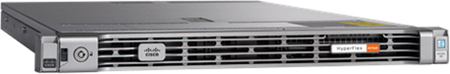
Figure 2-8 HXAF220c-M4S All Flash
Cisco HyperFlex HX220c-M4S Hybrid Node
Cisco HyperFlex HX220c-M4S Hybrid Node is a small-footprint Cisco HyperFlex hybrid model that contains six 1.8 TB or 1.2 TB SAS HDD drives that contribute to cluster storage capacity, a 120 GB or 240 GB SSD housekeeping drive, a 480 GB SAS SSD caching drive, and two Cisco Flexible Flash (FlexFlash) SD cards that act as boot drives. For configurations requiring self-encrypting drives, the caching SSD is replaced with an 800 GB SAS SED SSD, and the capacity disks are replaced with 1.2TB SAS SED HDDs.
Figure 2-9 shows the front view of an HX220c-M4S Hybrid node.

Figure 2-9 HX220c-M4S Hybrid
HX240 M5/M4 Series
The HX240C M5/M4 servers extend the capabilities of Cisco’s HyperFlex portfolio in a 2U form factor with the addition of the Intel Xeon processor scalable family with 24 DIMM slots.
HXAF240c-M5SX All Flash
HXAF240c-M5SX All Flash is a capacity-optimized Cisco HyperFlex all flash model that contains a 240 GB M.2 form factor SSD that acts as the boot drive, a 240 GB housekeeping SSD, either a single 375 GB Optane NVMe SSD or a 1.6 TB NVMe SSD or a 400 GB SAS SSD write-log drive installed in a rear hot-swappable slot, and 6 to 23 960 GB or 3.8 TB SATA SSDs for storage capacity. For configurations requiring self-encrypting drives, the caching SSD is replaced with an 800 GB SAS SED SSD, and the capacity disks are also replaced with either 800 GB, 960 GB, or 3.8 TB SED SSDs.
Figure 2-10 shows the front view of an HXAF240c-M5SX All Flash node.

Figure 2-10 HXAF240c-M5SX All Flash
HX240c-M5SX Hybrid
HX240c-M5SX Hybrid is a capacity-optimized Cisco HyperFlex hybrid model that contains a minimum of 6 and up to 23 1.8 TB or 1.2 TB SAS small form factor (SFF) HDDs that contribute to cluster storage, a 240 GB SSD housekeeping drive, a single 1.6 TB SSD caching drive installed in a rear hot-swappable slot, and a 240 GB M.2 form factor SSD that acts as the boot drive. For configurations requiring self-encrypting drives, the caching SSD is replaced with a 1.6 TB SAS SED SSD, and the capacity disks are replaced with 1.2TB SAS SED HDDs.
Figure 2-11 shows the front view of an HX240c-M5SX Hybrid node.
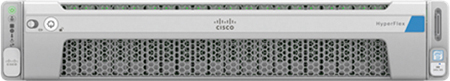
Figure 2-11 HX240c-M5SX Hybrid
HX240c-M5L Hybrid
HX240c-M5L Hybrid is a density-optimized Cisco HyperFlex hybrid model that contains a minimum of 6 and up to 12 6 TB or 8 TB SAS large form factor (LFF) HDDs that contribute to cluster storage, a 240 GB SSD housekeeping drive and a single 3.2 TB SSD caching drive (both installed in the rear hot-swappable slots), and a 240 GB M.2 form factor SSD that acts as the boot drive. Large form factor nodes cannot be configured with self-encrypting disks and are limited to a maximum of eight nodes in a cluster in the initial release of HyperFlex 3.0.
Figure 2-12 shows the front view of an HX240c-M5L Hybrid node.
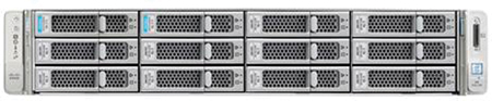
Figure 2-12 HX240c-M5L Hybrid
HXAF240c-M4SX All Flash
HXAF240c-M4SX All Flash is a capacity-optimized Cisco HyperFlex All Flash model that contains two FlexFlash SD cards that act as boot drives, a single 120 GB or 240 GB SSD data-logging drive, a single 400 GB NVMe or a 400 GB or 800 GB SAS SSD write-log drive, and 6 to 23 960 GB or 3.8 TB SATA SSDs for storage capacity. For configurations requiring self-encrypting drives, the caching SSD is replaced with an 800 GB SAS SED SSD, and the capacity disks are also replaced with either 800 GB, 960 GB, or 3.8 TB SED SSDs.
Figure 2-13 shows the front view of an HXAF240c-M4SX All Flash node.
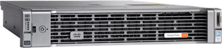
Figure 2-13 HXAF240c-M4SX All Flash
HX240c-M4SX Hybrid
HX240c-M4SX Hybrid is a capacity-optimized Cisco HyperFlex hybrid model that contains a minimum of 6 and up to 23 1.8 TB or 1.2 TB SAS HDDs that contribute to cluster storage, a single 120 GB or 240 GB SSD housekeeping drive, a single 1.6 TB SAS SSD caching drive, and two FlexFlash SD cards that act as the boot drives. For configurations requiring self-encrypting drives, the caching SSD is replaced with a 1.6 TB SAS SED SSD, and the capacity disks are replaced with 1.2TB SAS SED HDDs.
Figure 2-14 shows the front view of an HX240c-M4SX Hybrid node.
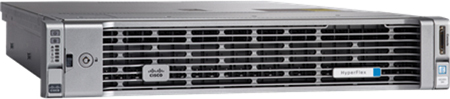
Figure 2-14 HX240c-M4SX Hybrid
HXAF220c-M5N All-NVMe
HXAF220c-M5N All-NVMe is a small-footprint Cisco HyperFlex all-NVMe model that contains a 240 GB M.2 form factor SSD that acts as the boot drive, a 1 TB housekeeping NVMe SSD, a single 375 GB Intel Optane NVMe SSD write-log drive, and six to eight 1 TB or 4 TB NVMe SSDs for storage capacity. Optionally, the Cisco HyperFlex Acceleration Engine card can be added to improve write performance and compression. Self-encrypting drives are not available as an option for the all-NVMe nodes.
Figure 2-15 shows the front view of an HXAF220c-M5N All-NVMe node.

Figure 2-15 HXAF220c-M5N All-NVMe
All Flash, Hybrid, and All-NVMe
Hybrid converged nodes use a combination of SSDs for the short-term storage caching layer and HDDs. All Flash nodes only make use of SSDs, and All-NVMe nodes use only Non-Volatile Memory Express (NVMe) drives.
Cisco HyperFlex Compute-Only Nodes
All current model Cisco UCS M4 and M5 generation servers, except the C880 M4 and C880 M5, may be used as compute-only nodes connected to a Cisco HyperFlex cluster, along with a limited number of previous M3 generation servers. Any valid CPU and memory configuration is allowed in the compute-only nodes, and the servers can be configured to boot from SANs, local disks, or internal SD cards. The following servers may be used as compute-only nodes:
Cisco UCS B200 M3 blade servers
Cisco UCS B200 M4 blade servers
Cisco UCS B200 M5 blade servers
Cisco UCS B260 M4 blade servers
Cisco UCS B420 M4 blade servers
Cisco UCS B460 M4 blade servers
Cisco UCS B480 M5 blade servers
Cisco UCS C220 M3 rack-mount servers
Cisco UCS C220 M4 rack-mount servers
Cisco UCS C220 M5 rack-mount servers
Cisco UCS C240 M3 rack-mount servers
Cisco UCS C240 M4 rack-mount servers
Cisco UCS C240 M5 rack-mount servers
Cisco UCS C460 M4 rack-mount servers
Cisco UCS C480 M5 rack-mount servers
Physical Installation
The servers connect to the fabric interconnects via the Cisco VIC 1227 mLOM card, the Cisco 1387 mLOM card, or the Cisco VIC 1457 mLOM card. The VIC 1227 card is used in conjunction with the Cisco UCS 6248UP or 6296UP model fabric interconnects, the VIC 1387 is used in conjunction with the Cisco UCS 6332 or 6332-16UP model fabric interconnects, and the Cisco UCS VIC 1457 is used in conjunction with the Cisco UCS 6454 model fabric interconnect.
The Cisco UCS Virtual Interface Card (VIC) 1227 is a dual-port Enhanced Small Form-Factor Pluggable (SFP+) 10 Gbps Ethernet and Fibre Channel over Ethernet (FCoE)-capable PCI Express (PCIe) modular LAN-on-motherboard (mLOM) adapter installed in the Cisco UCS HX-Series rack servers.
Figure 2-16 shows a Cisco VIC 1227 mLOM card.
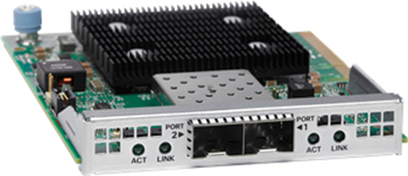
Figure 2-16 Cisco VIC 1227mLOM Card
The Cisco UCS VIC 1387 card is a dual-port Enhanced Quad Small Form-Factor Pluggable (QSFP+) 40 Gbps Ethernet and Fibre Channel over Ethernet (FCoE)-capable PCI Express (PCIe) mLOM adapter installed in the Cisco UCS HX-Series rack servers.
Figure 2-17 shows a Cisco VIC 1387 mLOM card.
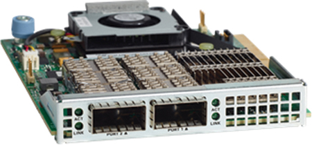
Figure 2-17 Cisco VIC 1387 mLOM Card
The Cisco UCS VIC 1457 is a quad-port Small Form-Factor Pluggable (SFP28) mLOM card designed for the M5 generation of Cisco UCS C-Series rack servers. The card supports 10/25 Gbps Ethernet or FCoE. The card can present PCIe standards-compliant interfaces to the host, and these can be dynamically configured as either NICs or HBAs.
Figure 2-18 shows a Cisco VIC 1457 mLOM card.
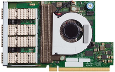
Figure 2-18 Cisco VIC 1457 mLOM Card
Supported Media
Table 2-2 through Table 2-9 list the Small Form-Factor Pluggable (SPF), Quad Small Form-Factor Pluggable (QSFP), cables with integrated transceivers, and cable specifications that are supported by the Cisco VIC 1227 mLOM card, Cisco VIC 1387 mLOM card, and Cisco VIC 1457 mLOM card.
Table 2-2 Cisco VIC 1227 mLOM Card SFP and Twinax Support
Connector (Media) |
Cable Type |
SFP-10G-USR |
Ultra-short-range MMF |
SFP-10G-SR |
Short-range MMF |
SFP-10G-LR |
Long-range SMF |
10GBASE-CU |
SFP+ cable 1, meter |
10GBASE-CU |
SFP+ cable 3, meter |
10GBASE-CU |
SFP+ cable 5, meter |
10GBASE-CU |
SFP+ cable 7, meter |
SFP-10GB-ACU |
Cable, 7 meter |
Table 2-3 Cisco VIC 1227 mLOM Card Cable Specifications
Connector (Media) |
Cable |
Distance |
Power (Each Side) |
Transceiver Latency (Link) |
Standard |
SFP+ CU copper |
Twinax |
5 meters |
Approximately 0.1 W |
Approximately 0.1 microseconds |
SFF 8431 |
SFP+ ACU copper |
Active Twinax |
7 meters/10 meters |
Approximately 0.5 W |
Approximately 6.8 nanoseconds |
SFF 8461 |
SFP+ SR MMF and SR |
MM OM2 MM OM3 |
82 meters/300 meters |
1 W |
Approximately 0 microseconds |
IEEE 802.3ae |
Table 2-4 Cisco VIC 1387 QSFP and QSA Support
Connector (Media) |
Cable Type |
QSFP-40G-SR4 |
40GBASE-SR4 QSFP+ transceiver module for MMF, 4 lanes, 850 nm wavelength, 12-fiber MPO/MTP connector |
QSFP-40G-SR4-S |
40GBASE-SR4 QSFP+ transceiver module for MMF, 4 lanes, 850 nm wavelength, 12-fiber MPO/MTP connector, S-class |
QSFP-40G-CSR4 |
40GBASE-CSR4 QSFP+ transceiver module for MMF, 4 lanes, 850 nm wavelength, 12-fiber MPO/MTP connector |
QSFP-40G-SR-BD |
40 Gbps QSFP BiDi optical transceiver |
QSFP-40G-LR4 |
40GBASE-LR4 QSFP+ transceiver module for SMF, duplex LC, 10-kilometer reach |
QSFP-40G-LR4-S |
40GBASE-LR4 QSFP+ transceiver module for SMF, duplex LC, 10-kilometer reach, S-class |
QSFP-4SFP10G-CU1M |
40GBASE-CR4 QSFP+ to 4 10GBASE-CU SFP+ direct attach breakout cable assembly, 1 meter passive |
QSFP-4SFP10G-CU3M |
40GBASE-CR4 QSFP+ to 4 10GBASE-CU SFP+ direct attach breakout cable assembly, 3 meter passive |
QSFP-H40G-CU1M |
Direct attach copper, 1 meter |
QSFP-H40G-CU3M |
Direct attach copper, 3 meter |
QSFP-H40G-CU5M |
Direct attach copper, 5 meter |
QSFP-H40G-ACU7M |
40GBASE-CR4 QSFP+ direct attach copper cable, 7 meter active |
QSFP-H40G-ACU10M |
40GBASE-CR4 QSFP+ direct attach copper cable, 10 meter active |
QSFP-4x10G-AC7M |
40GBASE-CR4 QSFP+ to 4 10GBASE-CU SFP+ direct attach breakout cable assembly, 7 meter active |
QSFP-4x10G-AC10M |
40GBASE-CR4 QSFP+ to 4 10GBASE-CU SFP+ direct attach breakout cable assembly, 10 meter active |
QSFP-H40G-AOC1M |
40 Gbps QSFP active optical cable, 1 meter |
QSFP-H40G-AOC2M |
40 Gbps QSFP active optical cable, 2 meter |
QSFP-H40G-AOC3M |
40 Gbps QSFP active optical cable, 3 meter |
QSFP-H40G-AOC5M |
40 Gbps QSFP active optical cable, 5 meter |
QSFP-H40G-AOC7M |
40 Gbps QSFP active optical cable, 7 meter |
QSFP-H40G-AOC10M |
40 Gbps QSFP active optical cable, 10 meter |
QSFP-4X10G-AOC1M |
QSFP to 4 SFP 10 Gbps active optical cable, 1 meter |
QSFP-4X10G-AOC2M |
QSFP to 4 SFP 10 Gbps active optical cable, 2 meter |
QSFP-4X10G-AOC3M |
QSFP to 4 SFP 10 Gbps active optical cable, 3 meter |
QSFP-4X10G-AOC5M |
QSFP to 4 SFP 10 Gbps active optical cable, 5 meter |
QSFP-4X10G-AOC7M |
QSFP to 4 SFP 10 Gbps active optical cable, 7 meter |
QSFP-4X10G-AOC10M |
QSFP to 4 SFP 10 Gbps active optical cable, 10 meter |
CVR-QSFP-SFP10G |
QSFP to SFP+ adapter (QSA) |
Table 2-5 Cisco VIC mLOM 1387 SFP and Twinax Support with QSA
Connector (Media) |
Cable Type |
SFP-10G-USR |
Ultra-short-range MMF |
SFP-10G-SR |
Short-range MMF |
SFP-10G-LR |
Long-range SMF |
10GBASE-CU |
SFP+ cable, 1 meter |
10GBASE-CU |
SFP+ cable, 3 meter |
10GBASE-CU |
SFP+ cable, 5 meter |
10GBASE-CU |
SFP+ cable, 7 meter |
SFP-10GB-ACU |
Cable, 7 meter |
Table 2-6 40 Gigabit Ethernet Cabling Specifications
Connector (Media) |
Cable |
Distance |
Power (Each Side) |
Transceiver Latency (Link) |
Standard |
SFP+ copper (CU) |
Twinax |
1, 3, and 5 meter |
Approximately 0.1 W |
Approximately 0.1 microsecond |
SFF 8431 |
SFP+ ACU copper |
Active Twinax |
7 meter 10 meter |
Approximately 0.5 W |
Approximately 0.1 microsecond |
SFF 8461 |
SFP+ FET |
MM OM2 MM OM3 MM OM4 |
25 and 100 meter |
1 W |
Approximately 0 microseconds |
IEEE 802.3ae |
SFP+ short reach (SR) and MMF |
MM OM2 MM OM3 MM OM4 |
82 and 300 meter |
1 W |
Approximately 0 microseconds |
IEEE 802.3ae |
SFP+ long reach (LR) |
SMF |
10 kilometer |
1 W |
Approximately 0 microseconds |
IEEE 802.3ae |
SFP+ long reach (ER) |
SMF |
40 kilometer |
1.5 W |
Approximately 0 microseconds |
IEEE 802.3ae |
SFP+ long reach (ZR) |
SMF |
80 kilometer |
1.5 W |
Approximately 0 microseconds |
IEEE 802.3ae |
Table 2-7 Cisco VIC 1457 SFP Support: SFP+ 10 Gbps Transceivers
Connector (Media) |
Cable Type |
SFP-10G-SR |
10GBASE-SR, 850 nm, MMF, 300 meter |
SFP-10G-SR-S |
10GBASE-SR, 850 nm, MMF, 300 meter, S-class |
SFP-10G-LR |
10GBASE-LR, 1310 nm, SMF, 10 kilometer |
SFP-10G-LR-S |
10GBASE-LR, 1310 nm, SMF, 10 kilometer, S-class |
Table 2-8 Cisco VIC 1457 SF28P Support: SFP28 25 Gbps Transceivers
Connector (Media) |
Cable Type |
SFP-25G-SR-S |
25G BASE SFP+, 850 nm, MMF, 400 meter, S-class |
SFP-10/25G-CSR-S(1) |
10/25GBASE-CSR SFP+, 850 nm, MMF, 400 meter, S-class |
Table 2-9 Cisco VIC 1457 Twinax Support
Connector (Media) |
Cable Type |
SFP-H10GB-CU1M |
10GBASE-CU SFP+ direct attach copper cable, 1 meter |
SFP-H10GB-CU1-5M(4) |
10GBASE-CU SFP+ direct attach copper cable, 1.5 meter |
SFP-H10GB-CU2M |
10GBASE-CU SFP+ direct attach copper cable, 2 meter |
SFP-H10GB-CU2-5M(4) |
10GBASE-CU SFP+ direct attach copper cable, 2.5 meter |
SFP-H10GB-CU3M |
10GBASE-CU SFP+ direct attach copper cable, 3 meter |
SFP-H10GB-CU5M |
10GBASE-CU SFP+ direct attach copper cable, 5 meter |
SFP-H10GB-ACU7M |
10GBASE-CU SFP+ direct attach active copper cable, 7 meter |
SFP-H10GB-ACU10M |
10GBASE-CU SFP+ direct attach active copper cable, 10 meter |
SFP-10G-AOC1M |
10GBASE active optical SFP+ cable, 1 meter |
SFP-10G-AOC2M |
10GBASE active optical SFP+ cable, 2 meter |
SFP-10G-AOC3M |
10GBASE active optical SFP+ cable, 3 meter |
SFP-10G-AOC5M |
10GBASE active optical SFP+ cable, 5 meter |
SFP-10G-AOC7M |
10GBASE active optical SFP+ cable, 7 meter |
SFP-10G-AOC10M |
10GBASE active optical SFP+ cable, 10 meter |
SFP-H25G-CU1M |
25GBASE-CU SFP28 direct attach copper cable, 1 meter |
SFP-H25G-CU2M |
25GBASE-CU SFP28 direct attach copper cable, 2 meter |
SFP-H25G-CU3M |
25GBASE-CU SFP28 direct attach copper cable, 3 meter |
SFP-25G-AOC1M |
25GBASE-AOC SFP28 active optical cable, 1 meter |
SFP-25G-AOC2M |
25GBASE-AOC SFP28 active optical cable, 2 meter |
SFP-25G-AOC3M |
25GBASE-AOC SFP28 active optical cable, 3 meter |
SFP-25G-AOC5M |
25GBASE-AOC SFP28 active optical cable, 5 meter |
SFP-25G-AOC7M |
25GBASE-AOC SFP28 active optical cable, 7 meter |
SFP-25G-AOC10M |
25GBASE-AOC SFP28 active optical cable, 10 meter |
Physical Topology
This section describes the supported topologies in which the HyperFlex HX Data Platform can be deployed. These topologies include the following:
HyperFlex standard cluster
HyperFlex stretch cluster
HyperFlex edge cluster
HyperFlex Standard Cluster/HyperFlex Extended Cluster Topology
The Cisco HyperFlex system is composed of a pair of Cisco UCS fabric interconnects along with up to 32 HX-Series rack-mount servers per cluster. Up to 32 compute-only servers can also be added per HyperFlex cluster. Adding Cisco UCS rack-mount servers and/or Cisco UCS 5108 blade chassis, which house Cisco UCS blade servers, allows for additional compute resources in an extended cluster design. Up to 8 separate HX clusters can be installed under a single pair of fabric interconnects. The two fabric interconnects both connect to every HX-Series rack-mount server, and both connect to every Cisco UCS 5108 blade chassis and Cisco UCS rack-mount server. Upstream network connections, also referred to as Northbound network connections, are made from the fabric interconnects to the customer data center network at the time of installation.
Figure 2-19 illustrates the topology for a standard HyperFlex cluster.
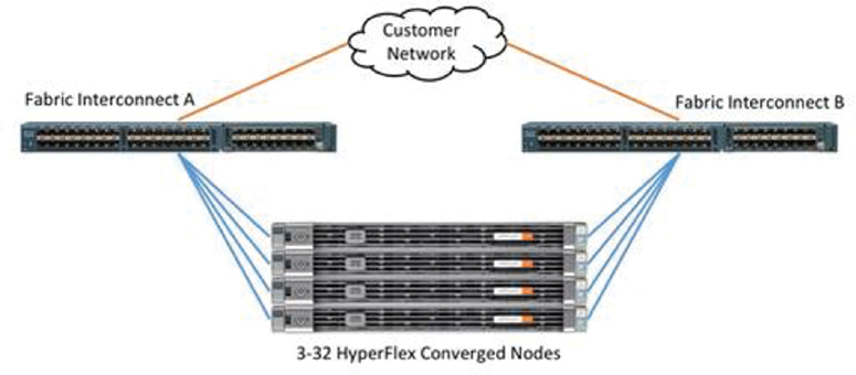
Figure 2-19 HyperFlex Standard Cluster Topology
Figure 2-20 illustrates the topology for an extended HyperFlex cluster.
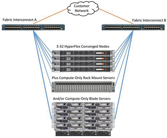
Figure 2-20 HyperFlex Extended Cluster Topology
Fabric Interconnect Connectivity
Fabric interconnects (FIs) are deployed in pairs, and the two units operate as a management cluster while forming two separate network fabrics, referred to as the A side and B side fabrics. Therefore, many design elements refer to FI A or FI B, alternatively called fabric A or fabric B. Both fabric interconnects are active at all times, passing data on both network fabrics for a redundant and highly available configuration. Management services, including Cisco UCS Manager, are also provided by the two FIs, but in a clustered manner, where one FI is the primary, and one is secondary, with a roaming clustered IP address. This primary/secondary relationship is only for the management cluster and has no effect on data transmission.
Fabric interconnects have the following ports, which must be connected for proper management of the Cisco UCS domain:
Mgmt: A 10/100/1000 Mbps port for managing the fabric interconnect and the Cisco UCS domain via GUI and CLI tools. This port is also used by remote KVM, IPMI, and SoL sessions to the managed servers within the domain. This is typically connected to the customer management network.
L1: A cross-connect port for forming the Cisco UCS management cluster. This port is connected directly to the L1 port of the paired fabric interconnect using a standard CAT5 or CAT6 Ethernet cable with RJ-45 plugs. It is not necessary to connect this to a switch or hub.
L2: A cross-connect port for forming the Cisco UCS management cluster. This port is connected directly to the L2 port of the paired fabric interconnect using a standard CAT5 or CAT6 Ethernet cable with RJ-45 plugs. It is not necessary to connect this to a switch or hub.
Console: An RJ-45 serial port for direct console access to the fabric interconnect. This port is typically used during the initial FI setup process with the included serial to RJ-45 adapter cable. This can also be plugged into a terminal aggregator or remote console server device.
HX-Series Rack-Mount Servers Connectivity
The HX-Series converged servers are connected directly to the Cisco UCS fabric interconnects in Direct Connect mode. This option enables Cisco UCS Manager to manage the HX-Series rack-mount servers using a single cable for both management traffic and data traffic. All the Cisco HyperFlex M4 generation servers are configured with the Cisco VIC 1227 or Cisco VIC 1387 network interface card (NIC) installed on the mLOM slot, which has dual 10 Gigabit Ethernet) or 40 Gigabit Ethernet ports. Cisco HyperFlex M5 generation servers can be configured only with the Cisco VIC 1387 card or the Cisco VIC 1457. The standard and redundant connection practice is to connect port 1 of the VIC (the right-hand port) to a port on FI A and port 2 of the VIC card (the left-hand port) to a port on FI B (0). An optional configuration method for servers containing the Cisco VIC 1457 card is to cable the servers with 2 links to each FI, using ports 1 and 2 to FI A, and ports 3 and 4 to FI B. The HyperFlex installer checks for this configuration and ensures that all servers’ cabling matches. Failure to follow this cabling practice can lead to errors, discovery failures, and loss of redundant connectivity.
All nodes within a Cisco HyperFlex cluster must be connected at the same communication speed—for example, mixing 10 Gb with 25 Gb interfaces is not allowed. In addition, for clusters that contain only M5 generation nodes, all the nodes within a cluster must contain the same model of Cisco VIC cards.
Various combinations of physical connectivity between the Cisco HX-Series servers and the fabric interconnects are possible, but only specific combinations are supported. For example, use of the Cisco QSA module to convert a 40 Gigabit Ethernet QSFP+ port into a 10 Gigabit Ethernet SFP+ port is not allowed with M4 generation servers but is allowed with M5 generation servers in order to configure a mixed cluster of M4 and M5 generation servers along with model 6248 or 6296 fabric interconnects. Table 2-10 lists the possible connections and which of these methods are supported.
Table 2-10 Supported Physical Connectivity
Fabric Interconnect Model |
6248 |
6296 |
6332 |
6332-16UP |
6454 |
||||
Port Type |
10 Gigabit Ethernet |
10 Gigabit Ethernet |
40 Gigabit Ethernet |
10 Gigabit Ethernet Breakout |
40 Gigabit Ethernet |
10 Gigabit Ethernet Breakout |
10 Gigabit Ethernet Onboard |
10 Gigabit Ethernet |
25 Gigabit Ethernet |
M4 with VIC 1227 |
✓ |
✓ |
— |
— |
— |
— |
— |
✓ |
— |
M4 with VIC 1387 |
— |
— |
✓ |
— |
✓ |
— |
— |
— |
— |
M4 with VIC 1387 + QSA |
— |
— |
— |
— |
— |
— |
— |
✓ |
— |
M5 with VIC 1387 |
— |
— |
✓ |
— |
✓ |
— |
— |
— |
— |
M5 with VIC 1387 + QSA |
✓ |
✓ |
— |
— |
— |
— |
— |
✓ |
— |
M5 with VIC 1457 or 1455 |
✓ |
✓ |
— |
— |
— |
— |
— |
✓ |
✓ |
Figure 2-21 illustrates the connectivity of an HX-Series server.
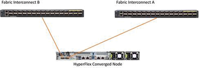
Figure 2-21 HX-Series Node Connectivity
Cisco UCS B-Series Blade Servers Connectivity
HyperFlex extended clusters also incorporate 1 to 16 Cisco UCS blade servers for additional compute capacity. A blade chassis comes populated with 1 to 4 power supplies and 8 modular cooling fans. In the rear of the chassis are two bays for installation of Cisco fabric extenders. The fabric extenders (also commonly called IO modules, or IOMs) connect the chassis to the fabric interconnects. Internally, the fabric extenders connect to the Cisco VIC installed in each blade server across the chassis backplane. The standard practice is to connect 1 to 8 10 Gigabit Ethernet links, or 1 to 4 40 Gigabit Ethernet links (depending on the IOMs and FIs purchased) from the left-side IOM, or IOM 1, to FI A, and to connect the same number of 10 Gigabit Ethernet or 40 Gigabit Ethernet links from the right-side IOM, or IOM 2, to FI B. All other cabling configurations are invalid and can lead to errors, discovery failures, and loss of redundant connectivity.
Figure 2-22 illustrates the connectivity for the Cisco UCS 5108 chassis.
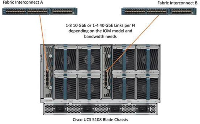
Figure 2-22 HyperFlex Cisco UCS 5108 Chassis Connectivity
HyperFlex Stretch Cluster Topology
A stretch cluster is geographically redundant, meaning that part of the cluster resides in one physical location, and another part resides in a second location. The cluster also requires a “tie breaker” or “witness” component, which should reside in a third, separate location. The goal of this design is to help ensure that the virtual infrastructure remains available even in the event of the complete loss of one site.
Figure 2-23 shows a logical representation of the components that are part of a HyperFlex stretch cluster.

Figure 2-23 Components of a Stretch Cluster
Characteristics of stretch cluster include the following:
A stretch cluster is a single cluster with nodes geographically distributed at different locations.
Storage is mirrored locally and across each site (but not to the tie-breaker witness).
Sites need to be connected over a low-latency network to meet the write requirements for applications and for a good end-user experience.
Geographic failover (using a virtual machine) is like failover in a regular cluster.
Node failure in a site is like node failure in a regular cluster.
Split brain is a condition in which nodes at either site cannot see each other. This condition can lead to problems if a node quorum cannot be determined (so that virtual machines know where to run). Split brain is caused by network failure or site failure.
Stretch clusters have a witness: an entity hosted on a third site that is responsible for deciding which site becomes primary after a split-brain condition.
A stretch cluster does have some physical limitations to keep in mind. Some applications, specifically databases, require write latency of less than 20 milliseconds (ms). Many other applications require latency of less than 10 ms to avoid problems with the application. To meet these requirements, the round-trip time (RTT) network latency on the stretch link between sites in a stretch cluster should be less than 5 ms. The speed of light (3e8 m/s) at the maximum recommended stretch cluster site distance of 100 km (approximately 62 miles) introduces about 1 ms of latency by itself. In addition, time is needed for code path and link hops (from node to fabric interconnect to switch), which also plays a role in determining the maximum site-to-site recommended distance.
Figure 2-24 shows a logical representation of a HyperFlex stretch cluster.
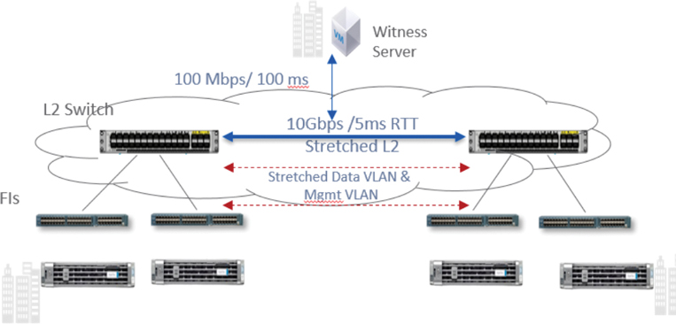
Figure 2-24 Stretch Cluster Network
Figure 2-25 illustrates the topology for a HyperFlex stretch cluster.
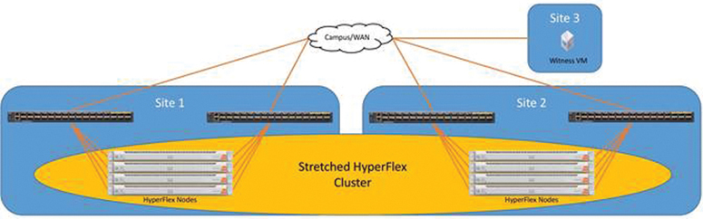
Figure 2-25 HyperFlex Stretch Cluster Topology
HyperFlex Edge Cluster Topology
A HyperFlex edge cluster is composed of two, three, or four Cisco UCS HX-Series converged nodes (with disk storage). Cluster node expansion is not supported but is planned for a future software release with 10 Gigabit Ethernet topologies. Each node is equipped with at least one high-performance SSD for data caching and rapid acknowledgment of write requests. Each node is also equipped with additional disks, up to the platform’s physical limit, for long-term storage capacity.
The following are the components of a Cisco HyperFlex Edge system:
Cisco HyperFlex HX-Series rack-mount servers, including the following models:
Cisco HyperFlex HX220c-M5SX rack-mount servers (2-, 3-, or 4-node configuration)
Cisco HyperFlex HXAF220c-M5SX All Flash rack-mount servers (2-, 3-, or 4-node configuration)
Cisco HyperFlex HX220c-M4S rack-mount servers (3-node configuration only)
Cisco HyperFlex HXAF220c-M4S All Flash rack-mount servers (3-node configuration only)
Cisco HyperFlex Data Platform software
VMware vSphere ESXi hypervisor
VMware vCenter Server (end user supplied)
In this solution, Cisco Intersight is the management platform that performs the deployment and administration of the HyperFlex Edge systems across multiple sites.
A Cisco HyperFlex edge cluster is built using Cisco HX-Series rack-mount servers that are not connected to Cisco UCS fabric interconnects. Upstream network connections, also referred to as Northbound network connections, are made directly from the servers to the customer-chosen data center top-of-rack (ToR) switches at the time of installation.
Figure 2-26 shows a logical topology for a HyperFlex edge cluster.

Figure 2-26 HyperFlex Edge Cluster Logical Topology
The following section describes the physical connectivity of the 3-node cluster. Chapter 7, “Deploying HyperFlex Anywhere with Intersight,” reviews the 2-node edge cluster.
Edge Network Connectivity
The Cisco HyperFlex Edge product supports three networking topologies: single Gigabit Ethernet switch, dual Gigabit Ethernet, and 10 Gigabit Ethernet switch (either single or dual) configurations, depending on requirements and the available switching hardware. This section describes specific requirements for each topology, as well as common network requirements that apply to all three topologies.
Single-Switch Configuration
A single-switch configuration provides a simple topology requiring only a single switch and two Gigabit Ethernet ports per server. Link or switch redundancy is not provided. Access ports and trunk ports are the two supported network port configurations.
Figure 2-27 illustrates the logical network topology of an edge cluster with a single upstream switch.
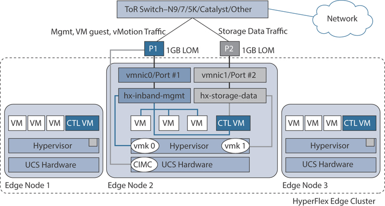
Figure 2-27 Edge Single-Switch Network Connectivity
The upstream network requirements are as follows:
A managed switch with VLAN capability
Six physical Gigabit Ethernet ports for three HyperFlex nodes
(Optional) Jumbo frames
PortFast or PortFast trunk configured on each port to ensure uninterrupted access
Two Gigabit Ethernet ports are required per server:
Port 1: For management (ESXi and Cisco Integrated Management Controller [CIMC]), vMotion traffic, and VM guest traffic
Port 2: For HyperFlex storage traffic
There are two supported network port configurations: access ports or trunk ports.
Spanning tree PortFast (access ports) or PortFast trunk (trunk ports) must be enabled for all network ports connected to HyperFlex servers. Failure to configure PortFast causes intermittent CIMC disconnects during ESXi bootup and longer-than-necessary network reconvergence during physical link failure.
Figure 2-28 illustrates the physical topology for a single switch from a single edge node.
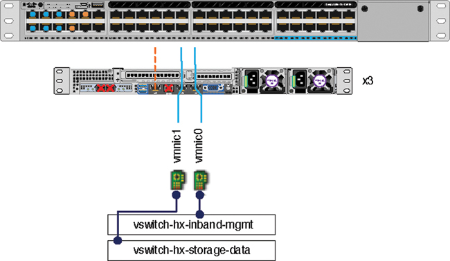
Figure 2-28 Edge Single-Switch Physical Topology
Some things to consider with this topology are as follows:
Cable both integrated LOM ports to the same ToR switch.
If desired, cable the dedicated CIMC port to the same switch or to an out-of-band management switch.
Do not use the 10 Gigabit Ethernet ports on the VIC.
Ethernet interfaces can be configured either as access ports or trunk ports, as follows:
An access port can have only one VLAN configured on the interface; it can carry traffic for only one VLAN.
A trunk port can have one or more VLANs configured on the interface; it can carry traffic for several VLANs simultaneously.
Table 2-11 summarizes the differences between access ports and trunk ports. You can use the details described in this table to determine which ports to use for a deployment.
Table 2-11 Trunk and Access Port Definitions
Trunk Ports |
Access Ports |
Requires more setup and definition of VLAN tags within CIMC, ESXi, and HX Data Platform installer. |
Provides a simpler deployment process than trunk ports. |
Provides the ability to logically separate management, vMotion, and VM guest traffic on separate subnets. |
Requires that management, vMotion, and VM guest traffic share a single subnet. |
Provides flexibility to bring in additional L2 networks to ESXi. |
Requires a managed switch to configure ports 1 and 2 on discrete VLANs; storage traffic must use a dedicated VLAN, with no exceptions. |
Dual-Switch Configuration
A dual-switch configuration provides a slightly more complex topology with full redundancy that protects against switch failure, link and port failure, and LOM/PCIe NIC HW failures. It requires two switches that may be standalone or stacked, and four Gigabit Ethernet ports and one additional PCIe NIC per server. Trunk ports are the only supported network port configuration.
Figure 2-29 illustrates the logical network topology of an edge cluster with dual upstream switch connectivity.
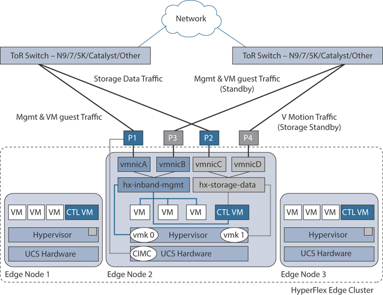
Figure 2-29 Edge Dual-Switch Network Connectivity
The upstream network requirements are as follows:
Two managed switches with VLAN capability (standalone or stacked)
12 physical Gigabit Ethernet ports for three HyperFlex nodes (All 12 ports must be configure as trunk and allow all applicable VLANs.)
(Optional) Jumbo frames
PortFast trunk configured on all ports to ensure uninterrupted access to CIMC)
Four Gigabit Ethernet ports are required per server:
Port 1: For management (ESXi, HyperFlex controller, and CIMC) and VM guest traffic
Port 2: For HyperFlex storage traffic (and vMotion standby)
Port 3: For VM guest traffic (and management standby)
Port 4: For vMotion traffic (and storage standby)
Two ports use LOM, and two ports are from a PCIe add-in NIC:
1 LOM port and 1 PCIe port serve management and VM guest traffic in a redundant configuration
1 LOM port and 1 PCIe port serve storage data and vMotion traffic in a redundant and load-balanced configuration
The Intel i350 quad-port NIC (UCSC-PCIE-IRJ45) must be installed for this topology:
The NIC may be selected at ordering time and shipped preinstalled from the factory.
The NIC may also be field-installed if ordered separately. Either riser 1 or riser 2 may be used, although riser 1 is recommended.
Only trunk ports are supported in the dual-switch configuration.
A spanning tree PortFast trunk must be enabled for every network port connected to HyperFlex servers. Failure to configure PortFast causes intermittent CIMC disconnects during ESXi bootup and longer-than-necessary network reconvergence during physical link failure.
Figure 2-30 illustrates the physical topology for a dual-switch configuration from a single edge node.
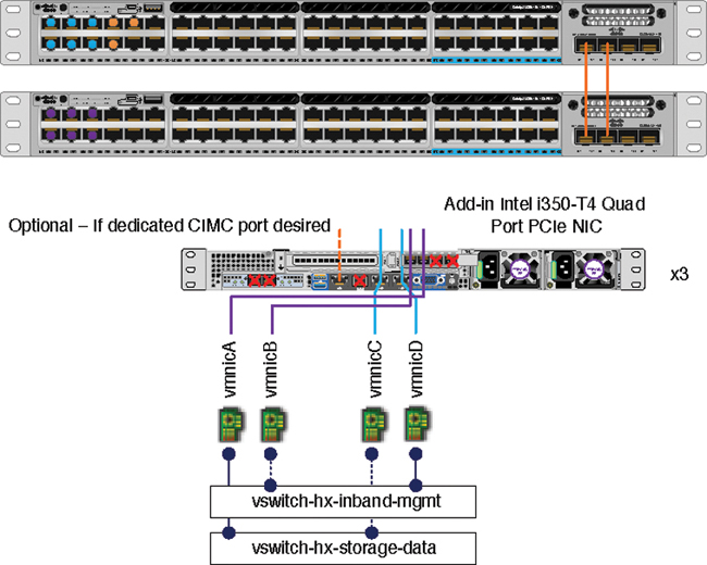
Figure 2-30 Edge Dual-Switch Physical Topology
Some things to consider with this topology are as follows:
Cable both integrated LOM ports to the same ToR switch.
Cable any two out of four PCIe NIC ports to the same ToR switch. Do not connect more than two PCIe NIC ports prior to installation. After cluster installation, you may freely use the remaining ports.
Redundancy occurs at the vSwitch level and includes one uplink port from the onboard LOM and one uplink port from PCIe NIC for each vSwitch.
If desired, cable the dedicated CIMC port to the same switch or to an out-of-band management switch.
Do not use the 10 Gigabit Ethernet ports on the VIC.
10 Gigabit Ethernet Switch Configuration
10 Gigabit Ethernet switch configuration provides a fully redundant technology that protects against switch (if using dual or stacked switches) and link and port failures. The 10 Gigabit Ethernet switch may be standalone or stacked. In addition, this configuration requires the following:
Two 10 Gigabit Ethernet ports and a VIC 1387 with two QSAs per server
Use of trunk mode
Deployment using the on-premise OVA installer and not Intersight
Figure 2-31 illustrates the logical network topology of an edge cluster with 10 Gigabit Ethernet upstream switch connectivity.

Figure 2-31 Edge 10 Gigabit Ethernet Dual-Switch Physical Connectivity
The upstream network requirements are as follows:
Two 10 Gbps ports are required per server using a VIC 1387:
Each physical VIC port is logically divided into 4 vNICs, as seen by the hypervisor.
Only 10 Gbps speeds are supported (no 40 Gbps).
M5 servers require VIC 1387 and two QSAs to reach 10 Gbps speeds.
M4 servers require VIC 1227 to reach 10 Gbps speeds.
Additional NICs:
Additional third-party NICs may be installed in the HX edge nodes, as needed.
All non-VIC interfaces must be shut down until the installation is complete.
Only a single VIC is supported per HX edge node.
Only trunk ports are supported in 10 Gigabit Ethernet switch configurations.
Spanning tree PortFast trunk should be enabled for all network ports connected to HX ports.
Figure 2-32 illustrates the physical topology for a 10 Gigabit Ethernet dual-switch configuration from a single edge node.
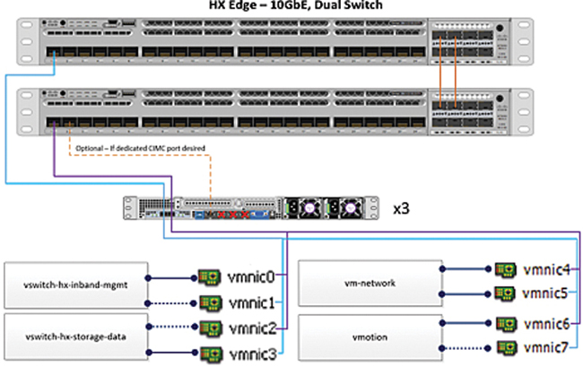
Figure 2-32 Edge 10 Gigabit Ethernet Dual-Switch Physical Topology
Some things to consider with this topology are as follows:
For M5 servers, ensure that a Cisco 40 Gigabit Ethernet-to-10 Gigabit Ethernet QSA is installed in both VIC ports.
If using a single 10 Gigabit Ethernet switch, cable both 10 Gigabit Ethernet ports to the same switch.
If using dual 10 Gigabit Ethernet switches or stacked switches, cable a 1X10 Gigabit Ethernet port to each switch, ensuring that all port 1s from all nodes go to the same switch and all port 2s from all nodes are connected to the other switch.
Cable the dedicated CIMC port to the same switch or to an out-of-band management switch.
Summary
This chapter presents the architecture of the HyperFlex HX Data Platform, including the components that make this solution possible. This chapter also reviews the different cluster topology configurations that are supported by the HyperFlex HX Data Platform. It discusses both the logical and physical topologies and the supported hardware for these topologies. Chapter 3, “Installing HyperFlex,” discusses deploying various types of HyperFlex clusters.