Chapter 5
Maintaining HyperFlex
Cisco HyperFlex Data Platform (HX Data Platform) is a hyperconverged software appliance that transforms Cisco servers into a single pool of compute and storage resources. It eliminates the need for network storage and enables seamless interoperability between computing and storage in virtual environments. Cisco HX-Data Platform provides a highly fault-tolerant distributed storage system that preserves data integrity and optimizes performance for virtual machine (VM) storage workloads. In addition, native compression and deduplication reduce the storage space occupied by the VMs and the VM workloads.
Cisco HX Data Platform has many integrated components, including Cisco fabric interconnects (FIs), Cisco UCS Manager, Cisco HX-specific servers, and Cisco compute-only servers; VMware vSphere, ESXi servers, and vCenter; and the Cisco HX Data Platform installer, controller VMs, HX Connect, vSphere HX Data Platform plug-in, and stcli commands.
This chapter provides details on managing a HyperFlex system and how to perform Day 2 operations on a HyperFlex cluster. It covers the following:
HyperFlex licensing
Virtual machine management
Snapshots
ReadyClones
Datastores
Scaling HyperFlex clusters
Node expansion (converged node and compute node)
Node removal (converged node and compute node)
Increasing storage capacity (by adding drives)
Hardware (disk) replacement
Replacing SSDs
Replacing NVMe SSDs
Replacing housekeeping SSDs
Replacing or adding HDDs
HyperFlex software upgrades
Pre-upgrade tasks
Upgrading UCS Server, ESXi, and HX Data Platform
HyperFlex Licensing
This section describes Smart Licensing in HyperFlex. Cisco Smart Software Licensing (Smart Licensing) is a cloud-based software license management solution that automates time-consuming manual licensing tasks, such as procuring, deploying, and managing licenses across an entire organization. The software allows for easy tracking of the status of license and software usage trends and simplifies the three core licensing functions: purchasing, management, and reporting. It provides visibility into your license ownership and consumption so you know what you own and how you are using it.
The Smart Licensing feature integrates with Cisco HyperFlex and is automatically enabled as soon as you create an HX storage cluster. For an HX storage cluster to start reporting license consumption, you must register it with Cisco Smart Software Manager (SSM) through your Cisco Smart Account. A Smart Account is a cloud-based repository that provides full visibility and access control to Cisco software licenses and product instances across your company. Registration is valid for one year.
Smart Account registration enables HyperFlex to be identified to a Smart Account and allows license usage to be reported to Cisco Smart Software Manager or a Smart Software Manager satellite. After registration, HyperFlex reports license usage to Cisco Smart Software Manager or a Smart Software Manager satellite with the current license status.
Registering a Cluster with Smart Licensing
Smart Licensing automatically integrates with your HX storage cluster and is enabled by default. Your HX storage cluster is initially unregistered with Smart Licensing and in a 90-day EVAL MODE. Within the 90 days, you need to register your HX storage cluster to use full functionality.
Figure 5-1 shows the Smart Licensing user workflow.

Figure 5-1 Smart Licensing User Workflow
Note
In order to begin using Smart Licensing, you need to have a Cisco Smart Account. You can create (or select) a Smart Account while placing an order, or you can create a Smart Account outside of placing an order and add new or existing licenses over time. To create a Smart Account, go to Cisco Software Central (https://software.cisco.com/) and click Get a Smart Account.
Creating a Registration Token
A registration token is used to register and consume a product for Smart Licensing. You must create a token to register the product and add the product instance to a specified virtual account. Follow these steps:
Step 1. Log in to the software manager at https://software.cisco.com/.
Step 2. In the License section, click Smart Software Licensing, as shown in Figure 5-2.
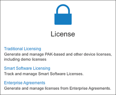
Figure 5-2 Cisco Software Central: License Section
Step 3. Under Smart Software Licensing, click Inventory.
Step 4. From the virtual account where you want to register your HX storage cluster, click the General tab and then click New Token (see Figure 5-3). The Create Registration Token dialog box appears.
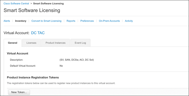
Figure 5-3 Smart Software Licensing: Inventory Page
Step 5. In the Create Registration Token dialog box (see Figure 5-4), do the following:
a. Add a short description for the token.
b. Enter the number of days you want the token to be active and available to use on other products. The maximum is 365 days.
c. Check Allow export-controlled functionality on the products registered with this token.
d. Click Create Token.

Figure 5-4 Creating a Registration Token
Note
In this case, I set the max number of uses to 1, so that I am the only one who can use this token.
As shown in Figure 5-5, the new token shows up under the list of tokens with the expiration date, number of uses, and user who created it.

Figure 5-5 New Token
Step 6. Select the token and copy it to the clipboard (see Figure 5-6).
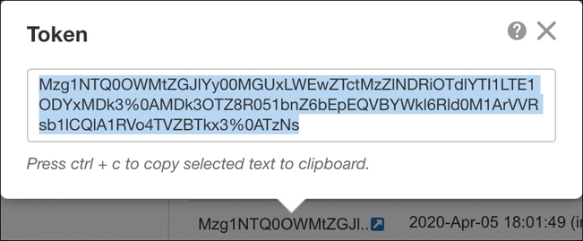
Figure 5-6 Copying a Token to the Clipboard
Registering a Cluster with Smart Software Licensing Through a Controller VM
This section covers an alternative method of registering a cluster with Smart Software Licensing through a controller VM. Follow these steps:
Step 1. Log in to a controller VM.
Step 2. Confirm that your HX storage cluster is in Smart Licensing mode by entering the following command:
# stcli license show status
As shown in Figure 5-7. the output should show “Smart Licensing is ENABLED, Status: UNREGISTERED, and the amount of time left in the 90-day evaluation period (in days, hours, minutes, and seconds). The Smart Licensing evaluation period starts when the HX storage cluster begins using the licensing feature and is not renewable. When the evaluation period expires, the Smart Agent sends a notification.

Figure 5-7 License Status Before Registration
Step 3. Register your HX storage cluster by using the command stcli license register --idtoken idtoken-string, where idtoken-string is the new ID token from Cisco Smart Software Manager or a Smart Software Manager satellite (see Figure 5-8). For more information on how to create a token for product instance registration, see the section “Creating a Registration Token,” earlier in this chapter.

Figure 5-8 Getting a Registration License
Step 4. Confirm that your HX storage cluster is registered by using the stcli license show summary command, as demonstrated in Figure 5-9.
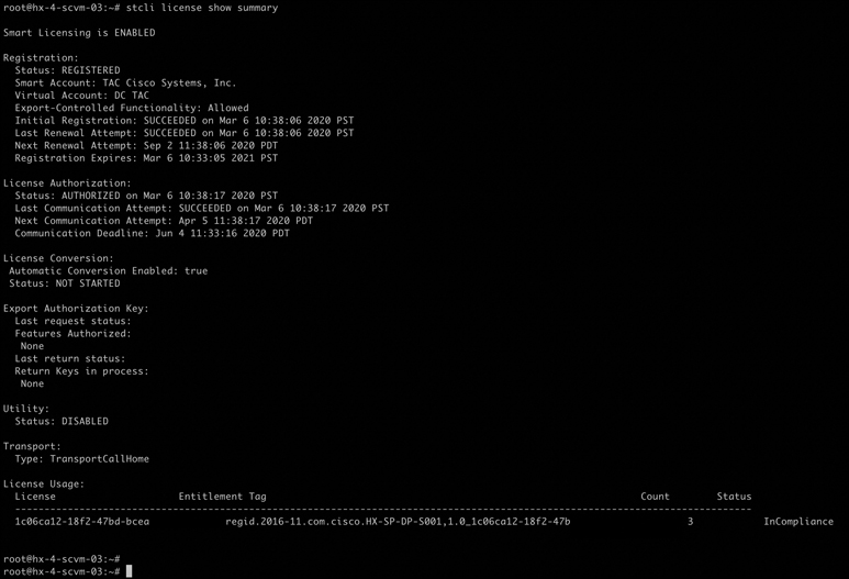
Figure 5-9 Confirming the Registration License
Virtual Machine Management
Cisco HyperFlex provides native virtual machine management features such as HX snapshots, ReadyClones, and datastore management. This section discusses the concepts, functionality, best practices, and configuration of these features in detail.
HX Data Platform Native Snapshots Overview
HX Data Platform Native Snapshots is a backup feature that saves versions (states) of working VMs. A native snapshot is a reproduction of a VM that includes the state of the data on all VM disks and the VM power state (on, off, or suspended) at the time the native snapshot is taken. You can take a native snapshot to save the current state of a VM so that you can later revert to the saved state.
You can use the HX Data Platform plug-in to take native snapshots of your VMs. The HX Data Platform Native Snapshot options include creating a native snapshot, reverting to any native snapshot, and deleting a native snapshot. Timing options include hourly, daily, and weekly, all in 15-minute increments.
Benefits of HX Data Platform Native Snapshots
HX Data Platform native snapshots provide the following benefits:
Reverting registered VMs: If a VM is registered, whether powered on or powered off, native snapshots, just like VM snapshots, can be used to revert to an earlier point in time (that is, time when the snapshot was created).
High performance: The HX Data Platform native snapshot process is fast because it does not incur I/O overhead.
VM performance: HX Data Platform native snapshots do not degrade VM performance.
Crash consistent: HX Data Platform native snapshots are crash consistent by default; this means the correct order of write operations is preserved, to enable an application to restart properly from a crash.
Application consistent: You can select the quiesce option of the stcli vm snapshot command through the HX Data Platform CLI to enable HX Data Platform native snapshots to be application consistent. The applications in the guest VM run transparently, exactly as they do in the host VM.
Quiescing a file system involves bringing the on-disk data of a physical or virtual computer into a state suitable for backups. This process might include operations such as flushing dirty buffers from the operating system’s in-memory cache to disk, as well as other higher-level application-specific tasks.
Scheduled snapshots are tolerant to node failures: Scheduled snapshots are tolerant to administrative operations that require a node shutdown, such as HX maintenance mode and HX online upgrades.
Unified interface: You can manage native snapshots created through the HX Data Platform plug-in by using the VMware snapshot manager.
Individual or grouped: You can take native snapshots on a VM level, VM folder level, or resource pool level.
Granular progress and error reporting: These monitoring tasks can be performed at task level for the resource pool, folder level, and VM level.
Instantaneous snapshot delete: Deletion of a snapshot and consolidation always occur instantaneously.
Parallel batch snapshots: HX supports up to 255 VMs in a resource pool or folder for parallel batched snapshots.
VDI deployment support: HX scheduled snapshots are supported for desktop VMs on VDI deployments using VMware native technology.
Recoverable VM: The VM is always recoverable when there are snapshot failures.
Datastore access: Snapshots work on partially mounted/accessible datastores as long as the VM being snapshotted is on an accessible mountpoint.
Native Snapshot Considerations
Some snapshot parameters to consider are as follows:
Native snapshots: After you create the first native snapshot using the HX Data Platform plug-in, if you create more snapshots in vSphere Web Client, these are considered to be native as well. However, if you create the first snapshot using vSphere Web Client and not the HX Data Platform plug-in, the vSphere Web Client snapshots are considered to be non-native.
Maximum number of stored snapshots: Currently VMware has a limitation of 31 snapshots per VM. This maximum total includes VMware-created snapshots, the HX Data Platform SENTINEL snapshot, and HX Data Platform native snapshots.
Scheduled snapshots: Do not schedule overlapping snapshots on VMs and their resource pools.
Deleted VMs: The life cycle of native snapshots, as with VM snapshots, is tied to the virtual machine. If a VM is deleted, accidentally or intentionally, all associated snapshots are also deleted. Snapshots do not provide a mechanism to recover from a deleted VM. Use a backup solution to protect against VM deletion.
HX Data Platform storage controller VMs: You cannot schedule snapshots for storage controller VMs.
Non-HX Data Platform VMs: Snapshots fail for any VM that is not on an HX Data Platform datastore. This applies to snapshots on a VM level, VM folder level, or resource pool level. To make a snapshot, the VM must reside on an HX Data Platform datastore in an HX Data Platform storage cluster.
Suspended VMs: Creating the first native snapshot, the SENTINEL snapshot, from VMs in suspended state is not supported.
VM Size: The maximum size of a VM that an HyperFlex snapshot can take depends on the maximum size of the individual Virtual Machine Disk (VMDK), maximum number of attached disks, and overall size of VM.
VM Name: The VM name must be unique per vCenter for taking a snapshot.
Ready storage cluster: To allow a native snapshot, the storage cluster must be healthy, including sufficient space, and online. The datastores must be accessible. The VMs must be valid and not in a transient state, such as in process of vMotion.
vMotion: vMotion is supported on VMs with native snapshots.
Storage vMotion: Storage vMotion is not supported on VMs with native snapshots. If a VM needs to be moved to a different datastore, delete the snapshots before running Storage vMotion.
VM datastores: Ensure that all the VM (VMDK) disks are on the same datastore prior to creating native snapshots. This applies to snapshots created with HX Snapshot Now and snapshots created with HX Scheduled Snapshots.
Thick disks: If the source disk is thick, then the snapshot of the VM’s disk will also be thick. Increase the datastore size to accommodate the snapshot.
Virtual disk types: VMware supports a variety of virtual disk backing types. The most common is the FlatVer2 format. Native snapshots are supported for this format. There are other virtual disk formats, such as Raw Device Mapping (RDM), SeSparse, and VmfsSparse (Redlog format). VMs containing virtual disks of these formats are not supported for native snapshots.
Native Snapshot Best Practices
Always use the HX Data Platform Snapshot feature to create your first snapshot of a VM. This ensures that all subsequent snapshots are in native format. Here are some additional recommended best practices:
Do not use the VMware Snapshot feature to create your first snapshot.
VMware snapshots use redo log technology that results in degraded performance of the original VM. This performance degrades further with each additional snapshot. Native format snapshots do not impact VM performance after the initial native snapshot is created. If you have any redo log snapshots, on the ESXi hosts where the redo log snapshots reside, edit the /etc/vmware/config file and set snapshot.asyncConsolidate="TRUE."
Add all the VMDKs to the VM prior to creating the first snapshot.
When VMDKs are added to the VM, additional SENTINEL snapshots are taken. Each additional SENTINEL consumes space for additional snapshots. For example, if you have an existing VM and you add two new VMDKs, at the next scheduled snapshot, one new SENTINEL is created. Check the snapshot schedule retention number to be sure you have sufficient snapshot slots available: one for the new SENTINEL and one for the snapshot.
When creating large numbers of snapshots, consider the following:
Schedule the snapshots at a time when you expect data traffic might be low.
Use multiple resource pools or VM folders to group VMs rather than using a single resource pool or VM folder. Then stagger the snapshot schedule by group. For example, for resourcePool1 schedule snapshots at :00, for resourcePool2 schedule snapshots at :15, and for resourcePool3 schedule snapshots at :30.
If you have vCenter running on a VM in the storage cluster, do not take a native snapshot of the vCenter VM.
Understanding SENTINEL Snapshots
When you create the first snapshot of a VM, through either Snapshot Now or Scheduled Snapshot, the HX Data Platform plug-in creates a base snapshot called a SENTINEL snapshot. The SENTINEL snapshot ensures that follow-on snapshots are all native snapshots.
SENTINEL snapshots prevent reverted VMs from having VMware redo log-based virtual disks. Redo log-based virtual disks occur when an original snapshot is deleted and the VM is reverted to the second-oldest snapshot.
SENTINEL snapshots are in addition to the revertible native snapshot. The SENTINEL snapshot consumes 1 snapshot of the total 31 available per the VMware limitation.
Keep in mind two important considerations when using SENTINEL snapshots:
Do not delete the SENTINEL snapshot.
Do not revert your VM to the SENTINEL snapshot.
Native Snapshot Timezones
Three objects display and affect the timestamps and schedule of snapshots:
vSphere and vCenter use UTC time.
vSphere Web Client uses the browser time zone.
HyperFlex Data Platform components such as the HX Data Platform plug-in, storage cluster, and storage controller VM use the same configurable time zone; the default is UTC.
The storage controller VM time is used to set the schedule. The vSphere UTC time is used to create the snapshots. The logs and timestamps vary depending on the method used to view them.
Creating Snapshots
Redo log snapshots are snapshots that are created through the VMware Snapshot feature and not through the HX Data Platform Snapshot feature. If you have any redo log snapshots for VMs in an HX storage cluster, edit the ESXi host configuration where the redo log snapshots reside. If this step is not completed, VMs might be stunned during snapshot consolidation. Follow these steps to edit the ESXi host configuration:
Step 1. Log in to the ESXi host command line.
Step 2. Locate and open the file /etc/vmware/config for editing.
Step 3. Set the snapshot.asyncConsolidate parameter to TRUE (that is, snapshot.asyncConsolidate="TRUE").
Creating Snapshots Workflow
Step 1. From the vSphere Web Client navigator, select the VM level, VM folder level, or resource pool level. For example, select vCenter Inventory Lists > Virtual Machines to display the list of VMs in vCenter.
Step 2. Select a VM and either right-click the VM and click Actions or click the Actions menu in the VM information portlet.
Note
Ensure that there are no non-HX Data Platform datastores on the storage cluster resource pool, or the snapshot will fail.
Step 3. From the Actions menu, select Cisco HX Data Platform > Snapshot Now, as shown in Figure 5-10, to open the Take VM Native Snapshot for Test dialog box.
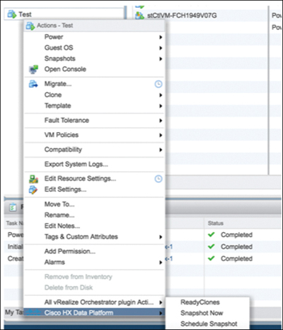
Figure 5-10 Selecting Snapshot Now
Step 4. In the Take VM Native Snapshot for Test dialog box (see Figure 5-11), enter a name for the snapshot and type a description of the snapshot. Click OK to accept your configuration.
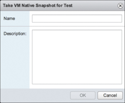
Figure 5-11 Adding a Native Snapshot Name and Description
Scheduling Snapshots
To schedule snapshots, follow these steps:
Step 1. From the vSphere Web Client navigator, select the VM or resource pool list. For example, select vCenter Inventory Lists > Virtual Machines to display the list of VMs in vCenter.
Step 2. Select a VM or resource pool and either right-click the VM or resource pool and click Actions or click the Actions menu in the VM information portlet.
Step 3. From the Actions menu, select Cisco HX Data Platform > Schedule Snapshot (see Figure 5-12) to open the Schedule Snapshot dialog box.
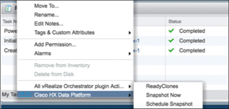
Figure 5-12 Scheduling a Snapshot
Step 4. Complete the Schedule Snapshot dialog box, shown in Figure 5-13, as follows:
a. To select the snapshot frequency, click the boxes for hourly, daily, and/or weekly frequency and set the starting days, times, and duration.
b. Set the number of snapshots to retain. When the maximum number is reached, older snapshots are removed as newer snapshots are created.
c. Unselect existing scheduled items, as needed. If a previous schedule existed, unselecting items deletes those items from the future schedule.
d. Click OK to accept the schedule and close the dialog.

Figure 5-13 Configuring the Schedule
Reverting to a Snapshot
Reverting to a snapshot means returning a VM to a state stored in a snapshot. Reverting to a snapshot is performed on one VM at a time. It is not performed at the resource pool or VM folder level. Reverting to snapshots is performed through the vCenter Snapshot Manager and not through the HX Data Platform plug-in. Follow these steps to revert to a snapshot:
Step 1. From the vSphere Web Client navigator, select the VM level, VM folder level, or resource pool level. For example, select vCenter Inventory Lists > Virtual Machines to display the list of VMs in vCenter.
Step 2. Select a storage cluster VM and either right-click the VM and click Actions or click the Actions menu in the VM information portlet.
Step 3. From the Actions menu, select Snapshots > Manage Snapshots (see Figure 5-14) to open the vSphere Snapshot Manager.
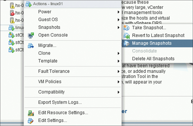
Figure 5-14 Managing Snapshots
Step 4. In the Snapshot Manager, select a snapshot to revert to from the hierarchy of snapshots for the selected VM and then select All Actions > Revert to, as shown in Figure 5-15.
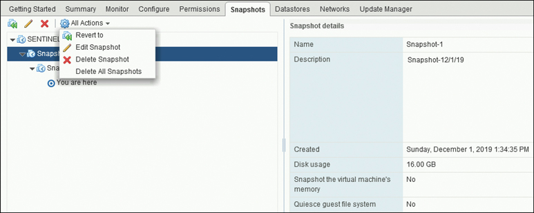
Figure 5-15 Reverting to a Snapshot
Step 5. Click Yes (to confirm the reversion (see Figure 5-16).
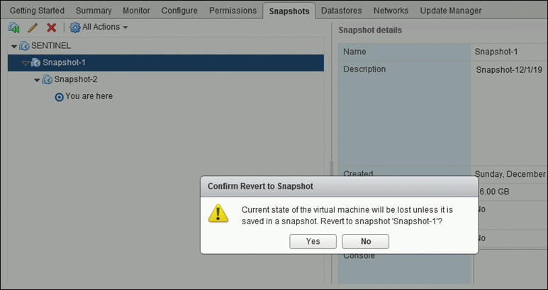
Figure 5-16 Confirm Revert to Snapshot Dialog Box
The reverted VM is included in the list of VMs and powered off. In selected cases, a VM reverted from a VM snapshot is already powered on. See Table 5-1 for more details.
Table 5-1 VM Power State After Restoring an HX VM Snapshot
VM State When HX VM Snapshot Is Taken |
VM State After Restoration |
Powered on (includes memory) |
Reverts to the HX VM snapshot, and the VM is powered on and running. |
Powered on (does not include memory) |
Reverts to the HX VM snapshot, and the VM is powered off. |
Powered off (does not include memory) |
Reverts to the HX VM snapshot, and the VM is powered off. |
Step 6. If the reverted VM is powered off, select the VM and power it on.
Deleting Snapshots
You delete snapshots through the vSphere interface and not through the HX Data Platform plug-in. Follow these steps:
Step 1. From the vSphere Web Client navigator, select VMs and Templates > vcenter_server > Snapshots > datacenter > VM.
Step 2. Right-click the VM and select Snapshots > Manage Snapshots.
Step 3. Right-click the snapshot you want to delete, click Delete.
Step 4. In the Confirm Delete dialog box that appears, click YES, as shown in Figure 5-17.
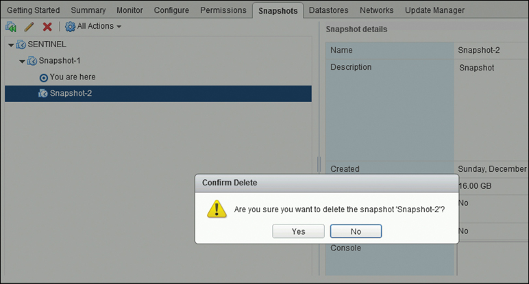
Figure 5-17 Deleting a Snapshot
Note
Delete the SENTINEL snapshot by using the Delete All option only. Do not delete the SENTINEL snapshot individually. This is because Sentinel snapshot is the base snapshot and all subsequent HX snapshots use this base snapshot.
ReadyClones
HX Data Platform ReadyClones is a pioneering storage technology that enables you to rapidly create and customize multiple cloned VMs from a host VM. It enables you to create multiple copies of VMs that can then be used as standalone VMs.
Clones are useful when you deploy many identical VMs to a group. A ReadyClone, much like a standard clone, is a copy of an existing VM. The existing VM is called the host VM. When the cloning operation is complete, the ReadyClone is a separate guest VM.
Changes made to a ReadyClone do not affect the host VM. A ReadyClone’s MAC address and UUID are different from those of the host VM.
Installing a guest operating system and applications can be time-consuming. With ReadyClones, you can make many copies of a VM from a single installation and configuration process.
Benefits of HX Data Platform ReadyClones
The HX Data Platform ReadyClones feature provides the following benefits:
Create multiple clones of a VM at a time: Simply right-click a VM and create multiple clones of the VM by using the ReadyClones feature.
Rapid cloning: HX Data Platform ReadyClones is extremely fast and more efficient than legacy cloning operations because it supports VMware vSphere Storage APIs—Array Integration (VAAI) data offloads. VAAI, also called hardware acceleration or hardware offload APIs, is a set of APIs to enable communication between VMware vSphere ESXi hosts and storage devices. Use HX Data Platform ReadyClones to clone VMs in seconds instead of minutes.
Batch customization of guest VMs: Use the HX Data Platform Customization Specification to instantly configure parameters such as IP address, hostname, and VM name for multiple guest VMs cloned from a host VM.
Automation of several steps to a one-click process: The HX Data Platform ReadyClones feature automates the task of creating guest VMs.
VDI deployment support: ReadyClones is supported for desktop VMs on VDI deployments using VMware native technology.
Datastore access: ReadyClones works on partially mounted/accessible datastores as long as the VM being cloned is on an accessible mountpoint.
Supported Base VMs
HX Data Platform supports:
Base VMs stored on an HX Data Platform datastore
Base VMs with HX Data Platform Snapshots
A maximum of 2048 ReadyClones from 1 base VM
A maximum of 256 ReadyClones created in 1 batch at a time
HX Data Platform does not support:
Powered-on base VMs with Windows 2008 Server and Windows 2012 Server guest
Powered-on base VMs with more than 30 snapshots
Powered-on base VMs with redo log snapshots
ReadyClones Requirements
The requirements for ReadyClones are as follows:
VMs must be within the HX Data Platform storage cluster. Non-HX Data Platform VMs are not supported.
VMs must reside on an HX Data Platform datastore, VM folder, or resource pool.
ReadyClones fail for any VM that is not on an HX Data Platform datastore. This applies to ReadyClones on a VM level, VM folder level, or resource pool level.
VMs can have only native snapshots. ReadyClones cannot be created from VMs with snapshots that have redo logs (that is, non-native snapshots).
SSH must be enabled in ESXi on all the nodes in the storage cluster.
You can use only the single vNIC customization template for ReadyClones.
ReadyClones Best Practices
When working with ReadyClones, keep the following best practices in mind:
Use the customization specification as a profile or a template.
Ensure that properties that apply to the entire batch are in the customization specification.
Obtain user-defined parameters from the HX Data Platform ReadyClones batch cloning workflow.
Use patterns to derive per-clone identity settings such as the VM guest name.
Ensure that the network administrator assigns static IP addresses for guest names and verify these addresses before cloning.
You can create a batch of 1 through 256 at a given time.
Do not create multiple batches of clones simultaneously on the same VM (when it is powered on or powered off) because doing so causes failures or displays incorrect information on the master task updates in the HX Data Platform plug-in.
Creating ReadyClones Using HX Connect
Use the HX Data Platform ReadyClones feature to populate a cluster by creating multiple clones of a VM, each with a different static IP address. Follow these steps:
Step 1. Log in to HX Connect as an administrator.
Step 2. From the Virtual Machines page, select a virtual machine and then click ReadyClones, as shown in Figure 5-18.
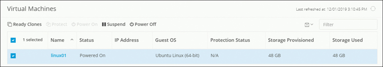
Figure 5-18 ReadyClones: Selecting a Virtual Machine
Step 3. Complete the ReadyClones dialog box, shown in Figure 5-19, as outlined in Table 5-2.
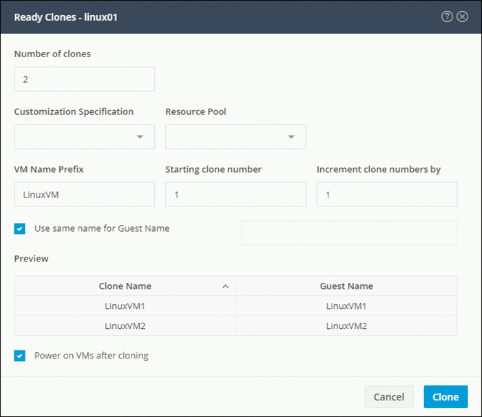
Figure 5-19 ReadyClones Dialog Box
Table 5-2 ReadyClones Dialog Box Fields
Field |
Setting |
Number of clones |
Enter the number of ReadyClones that you want to create. You can create a batch of 1 through 256 clones at a given time. |
Customization Specification |
(Optional) Click the drop-down list and select a customization specification for the clone from the drop-down list. The system filters the customization specifications for the selected host virtual machine. For example, if the selected host virtual machine uses Windows OS for guest virtual machines, the drop-down list displays Windows OS customization specifications. |
Resource Pool |
(Optional) If you have resource pools defined in an HX Storage cluster, you can select one to store the ReadyClones of the selected virtual machine. |
VM Name Prefix |
Enter a prefix for the guest virtual machine name. This prefix is added to the name of each ReadyClone created. |
Starting clone number |
Enter a clone number for the starting clone. Each ReadyClone must have a unique name; numbering is used to ensure a unique element in the name. |
Increment clone numbers by |
Enter a value by which the clone number in the guest virtual machine name must be increased or leave the default value 1 as is. The system appends a number to each the name of each virtual machine ReadyClone (such as clone1, clone2, and clone3). By default, the number starts from 1, but you can change this value to any number. |
Use same name for Guest Name |
Select this checkbox to use the vCenter VM inventory name as the guest host virtual machine name. If you uncheck this box, a text box is enabled. Enter the name you want to use for the guest host virtual machine name. |
Preview |
After required fields are completed, HX Data Platform lists the proposed ReadyClones names. As you change the content in the required fields, the Clone Name and Guest Name fields update. |
Power on VMs after cloning |
Select this checkbox to turn on the guest virtual machines after the cloning process completes. |
Step 4. Click Clone. HX Data Platform creates the appropriate number of ReadyClones with the naming and location specified.
Creating ReadyClones Using the HX Data Platform Plug-in
If you use the VMware cloning operation, you can create only a single clone from a VM. This operation is manual and slower than batch processing multiple clones from a VM. For example, to create 20 clones of a VM, you must manually perform the clone operation over and over again. Follow these steps to create ReadyClones using the HX Data Platform plug-in:
Step 1. From the vSphere Web Client navigator, select Global Inventory Lists > Virtual Machines to open a list of VMs in vCenter.
Step 2. Select a VM and either right-click the VM and click Actions or click the Actions menu in the VM information portlet.
Step 3. From the Actions menu, select Cisco HX Data Platform > ReadyClones, as shown in Figure 5-20.
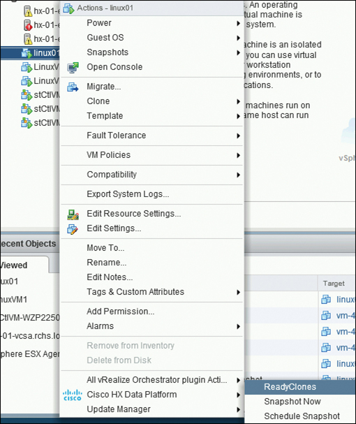
Figure 5-20 HX Data Platform ReadyClones Option
The ReadyClones dialog box appears, as shown in Figure 5-21.

Figure 5-21 ReadyClones Configuration
Step 4. Enter any changes you want to make and click OK to apply these configuration changes.
Note
As part of the ReadyClones workflow, a temporary snapshot is listed in vCenter and HX Connect. It is listed as an extra powered-off VM transiently—that is, only while the ReadyClones are being created.
Datastores
Datastores are logical containers that HX Data Platform uses to manage your storage usage and storage resources. Datastores are where the host places virtual disk files and other VM files. Datastores hide the specifics of physical storage devices and provide a uniform model for storing VM files.
You can add datastores, refresh the list, edit the names and sizes of datastores, delete datastores, and mount and unmount datastores from either HX Connect or the HX Data Platform plug-in. You can only rename an unpaired datastore that is unmounted. Do not rename a datastore using the vCenter administrator interface.
Keep in mind these important considerations:
Keep the number of datastores to as few as possible to avoid startup delay and to keep clone savings high.
Configuring more than 10 datastores could result in excessive startup delay.
Adding Datastores
Datastores are logical containers, similar to file systems, that hide specifics of physical storage and provide a uniform model for storing VM files. You can also use datastores to store ISO images and VM templates. To add a datastore, follow these steps:
Step 1. Choose an interface using either of these methods:
From the vSphere Web Client navigator, select vCenter Inventory Lists > Cisco HyperFlex Systems > Cisco HX Data Platform > cluster > Manage > Datastores.
From HX Connect, select Datastores.
Step 2. Click on create datastore.
Step 3. Enter a name for the datastore. vSphere Web Client enforces a 42-character limit for the datastore name, and each datastore name needs to be unique.
Step 4. Specify the datastore size and choose GB or TB from the drop-down list.
Step 5. Specify the data block size. From HX Connect, choose 8K or 4K; the default is 8K. In the HX Data Platform plug-in, the default is assumed. For VDI workloads, the default is 4k.
Step 6. Click OK to accept your changes or Cancel to cancel all changes.
Step 7. To verify the addition of the datastore, click the Refresh icon and ensure that the new datastore is listed. From the HX Data Platform plug-in, Click the Manage > Datastores > Hosts to see the mount status of the new datastore. If you check the datastore through the vSphere Client application, by selecting host > Configuration> Datastores, the drive type is listed as Unknown; this is expected vSphere behavior.
Creating Datastores Using the HX Data Platform Plug-in
The workflow in Figure 5-22 shows how to create datastores using the HX Data Platform plug-in on VMWare vCenter.

Figure 5-22 Create a Datastore by Using the HX Data Platform Plug-in
Creating Datastores Using HX Connect
Figure 5-23 shows how to create a datastore using HX Connect.

Figure 5-23 Creating a Datastore Using HX Connect
Scaling HyperFlex Clusters
One of the advantages of the HyperFlex solution is the ease with which you can scale an existing HyperFlex system. This section covers how to perform a node expansion, how to perform a node removal (for both converged and compute-only nodes), and how to increase storage capacity of existing HyperFlex nodes.
Node Expansion
You can add converged or compute-only nodes to expand a HyperFlex cluster. The following is the list of supported mixed-cluster expansion guidelines (for both converged and compute-only nodes) in HyperFlex clusters:
Expanding an existing M4 cluster with M5 converged nodes is supported.
Expanding an existing M5 cluster with M4 converged nodes is not supported.
Expanding an existing mixed M4/M5 cluster with M4 or M5 converged nodes is supported.
Adding any supported compute-only nodes is permitted with all M4, M5, and mixed M4/M5 clusters using the HX Data Platform installer.
Only the expansion workflow is supported for creating a mixed cluster. Initial cluster creation with mixed M4/M5 servers is not supported.
All M5 servers must match the form factor (220/240), type (hybrid/AF), security capability (non-SED only), and disk configuration (QTY, capacity, and non-SED) of the existing M4 servers.
HX Edge, SED, LFF, Hyper-V, and stretch clusters do not support mixed M4/M5 clusters.
Note
If you have replication configured, put replication in pause mode before performing an upgrade, an expansion, or cluster maintenance. After the upgrade, expansion, or cluster maintenance is complete, resume replication. Perform the pause and resume on any cluster that has replication configured to or from this local cluster.
ESXi installation is supported on SD cards for M4 converged nodes and M.2 SATA SSD for M5 converged nodes. For compute-only nodes, ESXi installation is supported for SD Cards, SAN boot, or front SSD/HDD. Installing ESXi on USB flash is not supported for compute-only nodes.
Before you start adding a converged or compute node to an existing storage cluster, make sure that the following prerequisites are met:
Ensure that the storage cluster state is healthy.
Ensure that the new node meets the system requirements listed under Installation Prerequisites, including network and disk requirements.
Ensure that the new node uses the same configuration as the other nodes in the storage cluster (for example, VLAN ID, tagging, vSwitch configuration and so on).
To add a node that has a different CPU family from what is already in use in the HyperFlex cluster, enable EVC.
Allow ICMP for pings between the HX Data Platform installer and the existing cluster management IP address.
The sections that follow describe how to add converged and compute-only nodes to expand a HyperFlex cluster.
Adding a Converged Node
You can add a converged node to a HyperFlex cluster after cluster creation. The storage on a converged node is automatically added to the cluster’s storage capacity.
Follow these steps to add a converged node to an existing standard cluster:
Step 1. Launch the Cisco HX Data Platform installer. (Use the same version of installer as the version of the HX cluster.)
Step 2. On the Workflow page, select Expand Cluster > Standard Cluster, as shown in Figure 5-24.
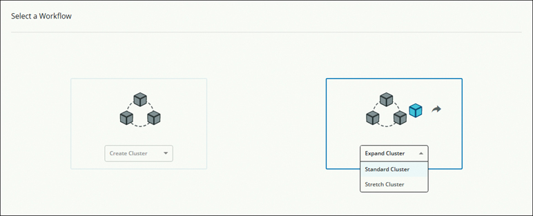
Figure 5-24 Cluster Expansion: Standard Cluster
Step 3. On the Credentials page that appears, complete all the fields, as shown in Figure 5-25, and click Continue.
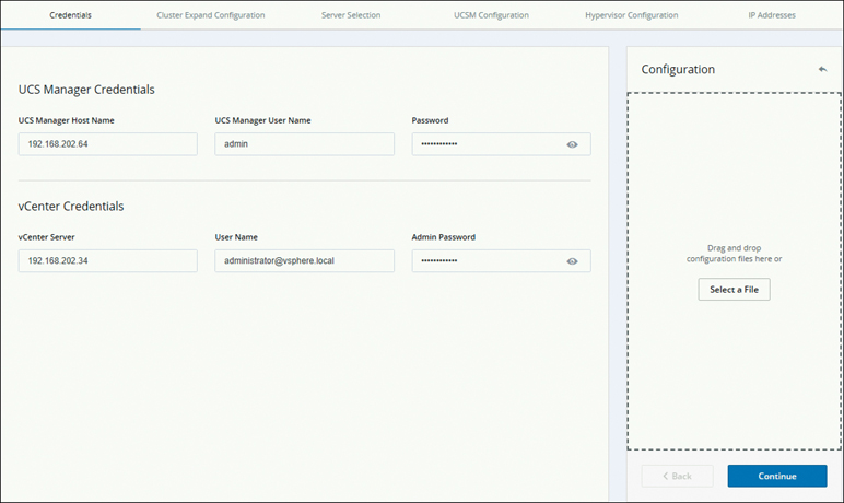
Figure 5-25 Expansion Workflow: Credentials Page
Step 4. On the Cluster Expand Configuration page that appears (see Figure 5-26), select the HX cluster that you want to expand and click Continue.
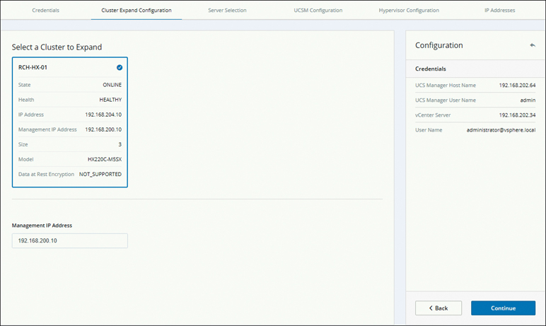
Figure 5-26 Selecting a Cluster to Expand
Step 5. On the Server Selection page, review the list of unassociated HX servers under the Unassociated tab (see Figure 5-27) and the list of discovered servers under the Associated tab. Select the servers under the Unassociated tab to include in the HyperFlex cluster. Click Continue.
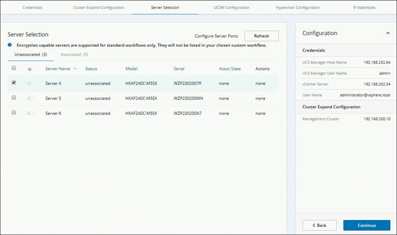
Figure 5-27 Selecting a Server
If HX servers do not appear in this list, check Cisco UCS Manager and ensure that they have been discovered.
Step 6. On the UCSM Configuration page that appears, complete the fields for each network and configure the HyperFlex cluster name, as shown in Figure 5-28, and click Continue.
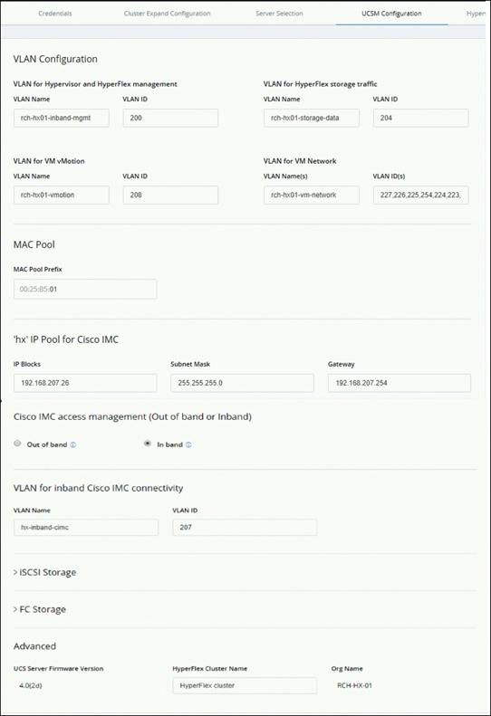
Figure 5-28 UCSM Configuration
Step 7. On the Hypervisor Configuration page that appears (see Figure 5-29), complete all the fields and click Continue.
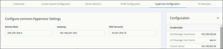
Figure 5-29 Hypervisor Configuration
Step 8. On the IP Addresses page that appears (see Figure 5-30), add more compute or converged servers, as desired, by clicking Add Compute Server or Add Converged Server. Be sure to select Make IP Addresses Sequential to make the IP addresses sequential. For the IP addresses, specify whether the network should belong to the data network or the management network. For each HX node, complete the appropriate fields for hypervisor management and data IP addresses. When you’re finished with the settings on this page, click Start. A Progress page displays the progress of various configuration tasks.
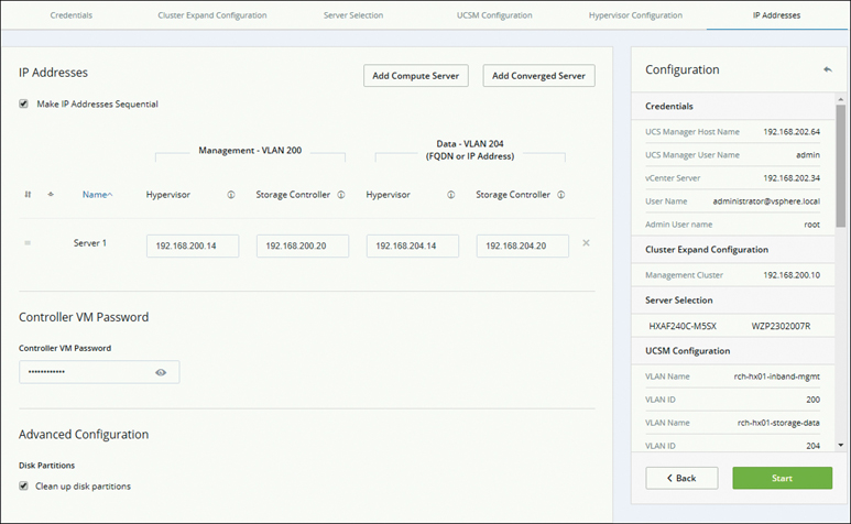
Figure 5-30 Configuring IP Addresses
Note
If the vCenter cluster has EVC enabled, the deployment process fails with the message “The host needs to be manually added to vCenter.” To successfully perform the deploy action, do the following:
Step 1. Log in to the ESXi host to be added in vSphere Client.
Step 2. Power off the controller VM.
Step 3. Add the host to the vCenter cluster in vSphere Web Client.
Step 4. In the HX Data Platform installer, click Retry Deploy.
Step 9. When cluster expansion is complete, start managing your storage cluster by clicking Launch HyperFlex Connect.
Note
When you add a node to an existing storage cluster, the cluster continues to have the same HA resiliency as the original storage cluster until auto-rebalancing takes place at the scheduled time. Rebalancing is typically scheduled during a 24-hour period, either 2 hours after a node fails or if the storage cluster is out of space.
Adding a Compute Node
You can add a compute-only node to a HyperFlex cluster after cluster creation to provide extra compute resources. The Cisco UCS server does not need to have any caching or persistent drives as they do not contribute any storage capacity to the cluster. Use similar steps for adding a compute node as used for expanding a HyperFlex cluster with a converged node.
Minor changes in the workflow as compared to converged node include the following:
Select Compute Only Server under Server Selection.
In the IP Addresses section, compute-only nodes do not need storage controller management and storage controller data.
Figure 5-31 shows the configuration option when adding a compute server.
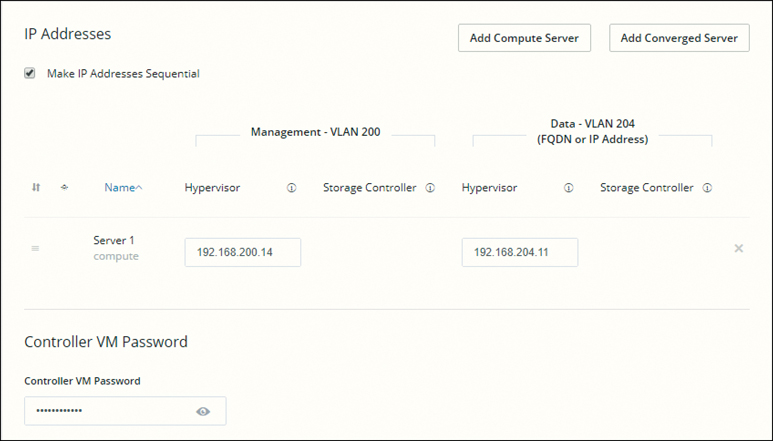
Figure 5-31 Adding a Compute Server
Note
After you add a compute-only node to an existing cluster, you must manually configure the vmk2 interface for vmotion.
Expanding a Stretch Cluster
You can perform cluster expansion on a HyperFlex stretch cluster when an already deployed stretch cluster has more storage utilization and requires expansion so that the storage capacity on a stretch cluster can be increased. After node expansion, the storage on a converged node is automatically added to the cluster’s storage capacity.
Consider the following cluster expansion guidelines:
Stretch cluster expansion supports both converged nodes and compute-only nodes.
When adding a converged node, ensure that the configuration is symmetric across both sites. For instance, if Site 1 is expanded with two nodes, Site 2 must also be expanded with two converged nodes.
When adding compute nodes, ensure that you do not exceed the supported node count.
To expand a stretch cluster, you need to take the steps outlined in the following sections.
Configuring Sites for Expanding a Cluster
Before you can expand a cluster, you need to re-create the sites in the installer as they are deployed using this procedure. Follow these steps:
Step 1. Log in to the Cisco HX Data Platform installer.
Step 2. On the Select a Workflow page, select Expand Cluster > Stretch Cluster, as shown in Figure 5-32, and click Continue.

Figure 5-32 Expansion Workflow: Stretch Cluster
Step 3. On the Cluster page that appears, enter the cluster management hostname, as shown in Figure 5-33, and click Continue.
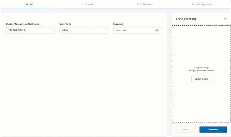
Figure 5-33 Cluster Information: Configuring a Site
Step 4. On the Credentials page that appears, as shown in Figure 5-34, select Configure Site and then enter UCS manager and hypervisor credentials. Click Continue.
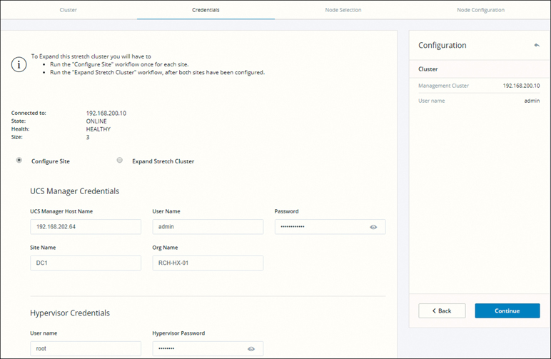
Figure 5-34 Credentials: Configuring a Site
Step 5. On the Server Selection page that appears, configure the server ports and associate the new HX expansion nodes with the site, as shown in Figure 5-35, and click Continue.
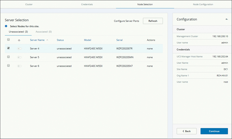
Figure 5-35 Node Selection
Step 6. On the Node Configuration page that appears, configure the subnet mask, gateway, and hypervisor settings as shown in Figure 5-36, and click Start to begin site configuration for the expanded cluster. A progress page displays the progress of various configuration tasks.
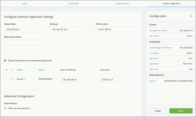
Figure 5-36 Node Configuration
Step 7. Repeat steps 1 through 7 for the second site.
Expanding a Cluster
To expand a cluster, follow these steps:
Step 1. On the Cluster page, as shown in Figure 5-37, enter the cluster management hostname and click Continue.
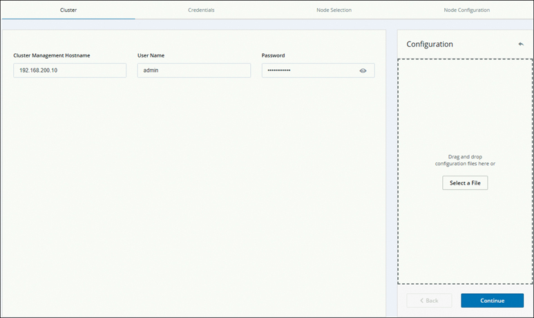
Figure 5-37 Cluster Information
Step 2. On the Credentials page that appears, as shown in Figure 5-38, select Expand Stretch Cluster, enter the credentials information, and click Continue.
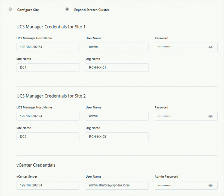
Figure 5-38 Expanding a Stretch Cluster
Step 3. Configure the server ports and associate HyperFlex servers.
Step 4. On the IP Addresses page, as shown in Figure 5-39, configure the hypervisor and IP addresses, select the site, and click Start to start the cluster expansion process.
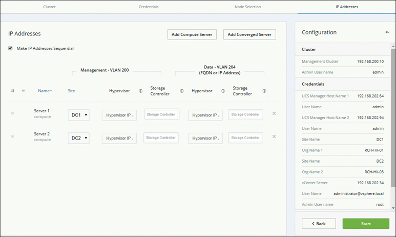
Figure 5-39 Expanding a Stretch Cluster by Adding a Converged Node
Removing Nodes
You can remove converged or compute-only nodes to reduce the size of a HyperFlex cluster. This section provides the guidelines for node removal of both converged and compute-only nodes in HyperFlex clusters.
Removing Converged Nodes
Depending on the node maintenance task, removing a node can occur while the storage cluster is online or offline. Ensure that you have completed the preparation steps before removing a node.
Note
It is highly recommended that you work with your account team when removing a converged node in a storage cluster. Do not reuse the removed converged node or its disks in the original cluster or in another cluster.
The steps to take in removing a node depend on the cluster size. Table 5-3 provides an overview of the steps for removing clusters of different sizes.
Table 5-3 Steps for Removing Converged Nodes
Cluster Size |
Nodes Removed |
Steps |
Three-node cluster |
One or more |
Cluster removal requires Cisco TAC assistance. |
Four-node cluster |
One |
|
Four-node cluster |
Two or more |
Cluster removal requires Cisco TAC assistance. |
Five-node cluster |
One |
|
Five-node cluster |
Two |
|
Five-node cluster |
Three or more |
Cluster removal requires Cisco TAC assistance. |
Removing a Node from an Online Storage Cluster
Depending on the node maintenance task, removing a node can occur while the storage cluster is online or offline. Removing a node from a storage cluster while the cluster remains online has slightly different requirements from removing a node while a cluster is offline. Follow these steps to remove a node from an online storage cluster:
Note
It is highly recommended that you work with TAC when removing a converged node in a storage cluster. Do not remove the controller VM or other HX Data Platform components.
Step 1. To prepare to remove a node, do the following:
Ensure that the cluster is healthy by entering the stcli cluster info command.
Ensure that SSH is enabled in ESX on all the nodes in the storage cluster.
Ensure that DRS is enabled or manually move the VMs from the node.
Put the node being removed into HX maintenance mode.
Log in to the controller VM of a node that is not being removed.
Step 2. Rebalance the storage cluster to ensure that all datastores associated with the node will be removed. The rebalance command is used to realign the distribution of stored data across changes in available storage and to restore storage cluster health. If you add or remove a node in the storage cluster, you can manually initiate a storage cluster rebalance by using the stcli rebalance command.
Note
Rebalancing might take some time, depending on the disk capacity used on the failed node or disk.
Log in to a controller VM in the storage cluster. From the controller VM command line, run the stcli rebalance start --force command and then wait and confirm that rebalance has completed.
Step 3. Remove the desired node by using the stcli node remove command, which has the following syntax:
stcli node remove [-h] {--id-1 ID1 | --ip-1 NAME1}
[{--id-2 ID2 | --ip-2 NAME2}] [-f]
For example:
# stcli node remove --name-1 esx.SVHOST144A.complab
The response should be something like the following:
Successfully removed node: EntityRef(type=3, id='', name=
'esx.SVHOST144A.complab')
Figure 5-40 shows this command in use.
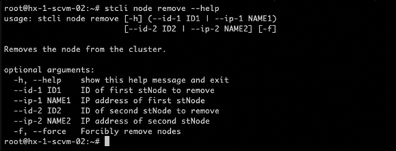
Figure 5-40 Running the stlci node remove Command
Note
The stlci node remove command unmounts all datastores, removes node from the cluster ensemble, resets the EAM for this node, stops all services (stores, cluster management IP), and removes all firewall rules. This command does not remove the node from vCenter; the node remains in vCenter. It also does not remove the installed HX Data Platform elements, such as the controller VM.
When the stcli node remove command completes successfully, the system rebalances the storage cluster until the storage cluster state is healthy. Do not perform any failure tests during this time. The storage cluster remains healthy.
As the node is no longer in the storage cluster, you do not need to exit HX maintenance mode.
Note
If you want to reuse a removed node in another storage cluster, contact Cisco TAC. Additional steps are required to prepare the node for another storage cluster.
Step 4. To confirm that the node has been removed from the storage cluster, run this command:
# stcli cluster info
Check the ActiveNodes entry in the response to verify that the cluster has one less node.
Step 5. Confirm that all the node-associated datastores are removed.
Note
If any node-associated datastores are listed, then manually unmount and delete those datastores.
Step 6. Remove the host from the vCenter Hosts and Cluster view as follows:
a. Log in to vSphere Web Client navigator and navigate to Host in the vSphere Inventory.
b. Right-click the host and select Enter Maintenance Mode. Click Yes.
c. Right-click the host and select All vCenter Actions > Remove from Inventory. Click Yes.
Step 7. Decommission the host from UCS Manager as follows:
a. Log in to UCS Manager.
b. In the navigation pane, Select Equipment > Chassis > Chassis Number > Servers.
c. Choose the HX server you want to decommission. In the work pane, click the General tab.
d. In the Actions area, click Server Maintenance.
e. In the Maintenance dialog box, click Decommission and then click OK.
Removing a Node from an Offline Storage Cluster
Removing a node from an offline storage cluster involves graceful shutdown of the HyperFlex cluster. Follow these steps:
Step 1. To prepare for maintenance operations and removing a node, do the following:
Ensure that the cluster is healthy.
Ensure that DRS is enabled or manually move the VMs from the node.
Rebalance the storage cluster.
Put the node being removed into HX maintenance mode.
Log in to the controller VM of a node that is not being removed.
Step 2. Prepare to shut down and then shut down the storage cluster as follows:
Note
Step 2 is required only if the cluster has fewer than five nodes or if you’re removing two nodes from a five-node cluster.
a. Gracefully shut down all resident VMs on all the HX datastores.
b. Optionally, vMotion the VMs.
c. Gracefully shut down all VMs on non-HX datastores on HX storage cluster nodes and unmount.
d. Put all storage cluster nodes in HX maintenance mode.
e. From any controller VM command line, issue the stcli cluster shutdown command:
# stcli cluster shutdown
Step 3. Remove the desired node by using the stcli node remove command. You can specify the node to be removed by either IP address or domain name, as in the following examples:
# stcli node remove --ip-1 10.10.2.4 --ip-2 10.10.2.6
or
# stcli node remove --name-1 esx.SVHOST144A.complab --name-2
esx.SVHOST144B.complab.lab
Note
Enter the second IP address if you are removing a second node from a storage cluster that has five or more nodes.
The response to this command should look something like the following:
Successfully removed node: EntityRef(type=3, id='',
name='10.10.2.4' name='10.10.2.6')
Note
The stlci node remove command unmounts all datastores, removes node from the cluster ensemble, resets the EAM for this node, stops all services (stores, cluster management IP), and removes all firewall rules. This command does not remove the node from vCenter; the node remains in vCenter. It also does not remove the installed HX Data Platform elements, such as the controller VM.
After the stcli node remove command completes successfully, the system rebalances the storage cluster until the storage cluster state is healthy. Do not perform any failure tests during this time. The storage cluster health remains average.
As the node is no longer in the storage cluster, you do not need to exit HX maintenance mode.
Note
If you want to reuse a removed node in another storage cluster, contact Cisco TAC. Additional steps are required to prepare the node for another storage cluster.
Step 4. To confirm that the node has been removed from the storage cluster, run this command:
# stcli cluster info
Check the ActiveNodes entry in the response to verify that the cluster has one less node.
Step 5. Confirm that all the node-associated datastores are removed.
Note
If any node-associated datastores are listed, manually unmount and delete those datastores.
Step 6. Restart the cluster by using the stcli cluster start command.
Removing a Compute Node
Compute-only nodes do not contribute to storage in a HyperFlex cluster. Therefore, when removing compute nodes, there is no limitation on the number of nodes you can remove. The steps to remove a compute node are as follows:
Step 1. Migrate all the VMs from a compute node that needs to be removed.
Step 2. Unmount the datastore from the compute node.
Step 3. Check whether the cluster is in the healthy state by running the following command:
# stcli cluster info --summary
Step 4. Put the ESXi host in HX maintenance mode.
Step 5. Remove the compute node by using the stcli node remove command from CMIP:
# stcli node remove --ip-1
Where --ip is the IP address of the node to be removed. (Use the Cisco HX Connect IP address as it is the cluster IP address.)
Step 6. Remove any DVS from the ESXi host in vCenter, if there is a DVS.
Step 7. Remove the ESXi host from vCenter.
Step 8. Check whether the cluster is in the healthy state by running the following command:
# stcli cluster info --summary
Step 9. Clear stale entries in the compute node by logging out of Cisco HX Connect and then logging into Cisco HX Connect.
Step 10. Disable and reenable the High Availability (HA) and Distributed Resource Scheduler (DRS) services to reconfigure the services after node removal.
Increasing Storage Capacity by Adding Drives
You can increase the datastore capacity of a storage cluster by adding drives if there is an available drive slot on the HyperFlex server.
Add the same size and type solid-state drives (SSDs) or hard disk drives (HDDs) to each converged node in the storage cluster. For hybrid servers, add HDDs. For all flash servers, add SSDs.
Note
When performing a hot-plug pull-and-replace on multiple drives from different vendors or of different types, pause for at least 30 seconds between actions. That is, pull a drive, wait 30 seconds and replace it, and wait 30 seconds again before moving on to the next drive.
Hardware (Disk) Replacement
Disks, whether SSDs or HDDs, might fail. If a disk failure occurs, you need to remove the failed disk and replace it. Follow the server hardware instructions for removing and replacing the disks in the host. HX Data Platform identifies the SSD or HDD and incorporates it into the storage cluster. The following sections provide details on how to replace the types of drives in HyperFlex.
Replacing SSDs
The procedures for replacing an SSD vary depending on the type of SSD, as described here:
Step 1. Identify the failed SSD:
For cache or persistent SSDs, perform a disk beacon check. Set the beacon. Only cache and persistent SSDs respond to the beacon request. NVMe cache SSDs and housekeeping SSDs do not respond to beacon requests.
For cache NVMe SSDs, perform a physical check. These drives are in Drive Bay 1 of the HX servers.
For housekeeping SSDs on HXAF240c or HX240c servers, perform a physical check at the back of the server.
For housekeeping SSDs on HXAF220c or HX220c servers, perform a physical check at Drive Bay 2 of the server.
Step 2. If the failed SSD is a housekeeping SSD, refer to the section “Replacing Housekeeping SSDs,” later in this chapter.
Step 3. If a failed SSD is a cache or persistent SSD, proceed based on the type of disk:
For NVMe SSDs, see the next section, “Replacing NVMe SSDs.”
For all other SSDs, follow the instructions for removing and replacing a failed SSD in the host, per the server hardware guide.
After the cache or persistent drive is replaced, the HX Data Platform identifies the SDD and updates the storage cluster. When disks are added to a node, the disks are immediately available for HX consumption.
Step 4. To enable Cisco UCS Manager to include new disks in the UCS Manager > Equipment > Server > Inventory > Storage tab, re-acknowledge the server node. This applies to cache and persistent disks.
Note
Re-acknowledging a server is disruptive, so place the server into HX maintenance mode before doing so.
Step 5. If you have replaced an SSD and see the message “Disk successfully scheduled for repair,” it means the disk is present but is still not functioning properly. Check that the disk has been added correctly per the server hardware guide procedures.
Replacing NVMe SSDs
The procedures for replacing an SSD vary depending on the type of SSD. This section describes the steps for replacing NVMe cache SSDs.
Note
Mixing storage disk types or sizes on a server or across a storage cluster is not supported. Also, when replacing NVMe disks, always use the same type and size as the original disk.
The requirements for using NVMe in HX are as follows:
NVMe SSDs are supported in HX240 and HX220 All Flash servers.
Replacing NVMe SSDs with an HGST SN200 disk requires HX Data Platform version 2.5.1a or later.
NVMe SSDs are only allowed in slot 1 of the server. Other server slots do not detect NVMe SSDs.
NVMe SSDs are only used for cache. Using them for persistent storage is not supported.
Using an NVMe SSD as the housekeeping drive is not supported.
Using NVMe SSDs for hybrid servers is not supported.
The steps for replacing NVMe SSDs are as follows:
Step 1. Confirm that the failed disk is an NVMe cache SSD by performing a physical check. These drives are in Drive Bay 1 of the HX servers. NVMe cache SSDs and housekeeping SSDs do not respond to beacon requests. If the failed SSD is not an NVMe SSD, see the earlier section “Replacing SSDs.”
Step 2. Put the ESXi host into HX maintenance mode by logging in to HX Connect and selecting System Information > Nodes > node > Enter HX Maintenance Mode.
Step 3. Follow the instructions for removing and replacing a failed SSD in the host, per the server hardware guide.
Note
When you remove an HGST NVMe disk, the controller VM fails until you reinsert a disk of the same type into the same slot or reboot the host.
After the cache or persistent drive is replaced, HX Data Platform identifies the SDD and updates the storage cluster. When disks are added to a node, the disks are immediately available for HX consumption.
Step 4. Reboot the ESXi host. This enables ESXi to discover the NVMe SSD.
Step 5. Exit the ESXi host from HX maintenance mode.
Step 6. To enable the Cisco UCS Manager to include new disks in the UCS Manager > Equipment > Server > Inventory > Storage tab, re-acknowledge the server node. This applies to cache and persistent disks.
Note
Re-acknowledging a server is disruptive, so place the server into HX maintenance mode before doing so.
Step 7. If you replaced an SSD and see the message “Disk successfully scheduled for repair,” it means that the disk is present but is still not functioning properly. Check that the disk has been added correctly per the server hardware guide procedures.
Replacing Housekeeping SSDs
This procedure applies to HXAF220c M4, HX220c M4, HXAF220c M5, HX220c M5, HXAF240c M5, and HX240c M5 servers only. To replace the housekeeping SSD on an HXAF240c M4 or HX240c M4 server, contact Cisco TAC.
To replace a housekeeping SSD, perform the following steps:
Step 1. Identify the failed housekeeping SSD by physically checking the SSD drives, as housekeeping drives are not listed through a beacon check.
Step 2. Remove the SSD and replace it with a new SSD of the same kind and size. Follow the steps in the server hardware guide, which should describe the physical steps required to replace the SSD.
Note
Before performing the hardware steps, put the node into HX maintenance mode. After performing the hardware steps, exit the node from HX maintenance mode.
Step 3. Using SSH, log in to the storage controller VM of the affected node and run the following command:
# /usr/share/springpath/storfs-appliance/config-bootdev.sh
-r -y
This command consumes the new disk, adding it into the storage cluster.
A sample response might resemble the following:
Creating partition of size 65536 MB for /var/stv ...
Creating ext4 filesystem on /dev/sdg1 ...
Creating partition of size 24576 MB for /var/zookeeper ...
Creating ext4 filesystem on /dev/sdg2 ...
Model: ATA INTEL SSDSC2BB12 (scsi)
Disk /dev/sdg: 120034MB
Sector size (logical/physical): 512B/4096B
Partition Table: gpt ....
discovered. Rebooting in 60 seconds
Step 4. Wait for the storage controller VM to automatically reboot.
Step 5. When the storage controller VM completes its reboot, verify that partitions are created on the newly added SSD by running the df -ah command.
A sample response might resemble the following:
...........
/dev/sdb1 63G 324M 60G 1%
/var/stv /dev/sdb2 24G 173M 23G 1% /var/zookeeper
Step 6. Identify the HX Data Platform installer package version installed on the existing storage cluster by running the stcli cluster version command. The same version must be installed on all the storage cluster nodes. Run this command on the controller VM of any node in the storage cluster but not the node with the new SSD.
Step 7. Copy the HX Data Platform installer packages into the storage controller VM in the /tmp folder:
# scp <hxdp_installer_vm_ip>:/opt/springpath/packages/storfs-
packages-<hxdp_installer>.tgz /tmp

# cd /tmp

# tar zxvf storfs-packages-<hxdp_installer>.tgz
Step 8. Run the HX Data Platform installer deployment script:
# ./inst-packages.sh
Note
For additional information on installing the HX Data Platform, see the appropriate Cisco HX Data Platform Install Guide.
Step 9. After the package installation, the HX Data Platform starts automatically. Check the status:
# status storfs
storfs running
The node with the new SSD rejoins the existing cluster, and the cluster returns to a healthy state.
Replacing or Adding HDDs
This section covers how to replace or add HDDs in HyperFlex servers/systems.
Note
Mixing storage disk types or sizes on a server or across a storage cluster is not supported.
The requirements for using HDDs in HX are as follows:
Use all HDDs or all 3.8 TB SSDs or all 960 GB SSDs.
Use the hybrid cache device on hybrid servers and all flash cache devices on all flash servers.
When replacing cache or persistent disks, always use the same type and size as the original disk.
To replace or add an HDD, follow these steps:
Step 1. Refer to the hardware guide for your server and follow the directions for adding or replacing disks.
Step 2. Add HDDs of the same size to each node in the storage cluster.
Step 3. Add the HDDs to each node within a reasonable amount of time. The storage starts being consumed by a storage cluster immediately.
After performing the steps, the vCenter event log will display messages reflecting the changes to the nodes.
Note
When disks are added to a node, the disks are immediately available for HX consumption, although they are not seen in the UCSM server node inventory. This includes cache and persistent disks.
Step 4. To enable Cisco UCS Manager to include new disks in the UCS Manager > Equipment > Server > Inventory > Storage tab, re-acknowledge the server node. This applies to cache and persistent disks.
Note
Re-acknowledging a server is disruptive, so place the server into HX maintenance mode before doing so.
Upgrading HyperFlex Software
This section describes how to upgrade an existing installation of Cisco HX Data Platform. Cisco HyperFlex systems have several components that may be upgraded, depending on the environment. The core components in a HyperFlex system are:
Cisco UCS server firmware (the UCS C-bundle, which consists of UCS server, BIOS, CIMC, NIC, and so on)
Cisco HX Data Platform software
VMware ESXi software
The following sections describe the HyperFlex upgrade process.
Upgrading HyperFlex
This section provides an overview of the HyperFlex software upgrade workflow. The complete upgrade process can be divided into two parts (see Figure 5-41):
Pre-upgrade steps:
Download the relevant UCS Infra, B-Series, C-Series, and HX upgrade storfs bundles.
Perform a manual pre-upgrade validation and run the Hypercheck pre-upgrade utility for a pre-upgrade and health check.
Upgrade the UCS infrastructure firmware.
Upgrade steps: Upgrade HX Data Platform, UCS server firmware, and VMware ESXi vSphere.
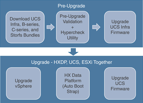
Figure 5-41 HyperFlex Upgrade Workflow
The following sections cover the upgrade workflow steps in detail.
Pre-Upgrade Workflow
Ensure you have reviewed the following important guidelines before scheduling a HyperFlex upgrade:
Step 1. See the resolved caveats and open caveats before upgrading and review the new features for this release. Refer to the corresponding Cisco HX Data Platform release notes. Visit https://www.cisco.com/c/en/us/support/hyperconverged-systems/HyperFlex-hx-data-platform-software/products-release-notes-list.html.
Step 2. Review the supported versions and system requirements. Refer to the hardware and software interoperability information for Cisco HyperFlex HX-Series. Be sure to verify that you have the latest software bundle versions and review the software versions. Refer to the latest Cisco HX Data Platform release notes.
Note
Hardware and Software Interoperability information can be found in release notes for specific HX releases
Step 3. Back up the configuration to an All Configuration backup file. See the Cisco UCS Manager Backing Up and Restoring the Configuration Guide for the detailed steps https://www.cisco.com/c/en/us/td/docs/unified_computing/ucs/ucs-manager/GUI-User-Guides/Admin-Management/3-1/b_Cisco_UCS_Admin_Mgmt_Guide_3_1/b_Cisco_UCS_Admin_Mgmt_Guide_3_1_chapter_01001.html.
Step 4. Before you perform firmware updates, use the Cisco UCS Manager firmware management interface to download relevant images to the fabric interconnect. Images are stored in bootflash partitions in the fabric interconnect.
Step 5. If needed, perform an ESXi upgrade when upgrading to newer Cisco HyperFlex HX Data Platform versions. See the supported versions for each HX Data Platform version in HyperFlex Software Versions.
Step 6. Keep SSH enabled on all ESXi hosts.
Step 7. Enable vMotion so that the VMs can be moved automatically during the upgrade and MTUs are set as required in the environment.
Step 8. Verify that the HyperFlex cluster is healthy.
Step 9. Verify that the cluster is in lenient mode. If it is not, set the cluster to lenient mode.
Downloading UCS Infra, B-Series, C-Series, and Storfs Bundles
For a successful HyperFlex upgrade, the Cisco HyperFlex System component bundles can be downloaded from the Cisco HyperFlex Downloads page on Cisco.com. Browse to https://software.cisco.com/download/home and search for each of the following, depending on the upgrading version:
HX Data Platform upgrade bundle (.tgz file): As an example, Figure 5-42 shows the HyperFlex Data Platform Upgrade bundle for upgrading HX clusters to version 3.5(2h).

Figure 5-42 HX Data Platform Upgrade Bundle
VMware ESXi Offline Zip bundle: As an example, Figure 5-43 shows the offline bundle for upgrading ESXi using Cisco HX Custom Image to version 6.5U3.

Figure 5-43 Offline Bundle for Upgrading ESXi: Cisco HX Custom Image
Cisco UCS infrastructure bundle, blade firmware bundle, and rack-mount firmware bundle: As an example, Figure 5-44 shows the UCS Infrastructure software bundle for 6200, 6300, and 6400 fabric interconnects, UCS B-Series blade server software, and UCS C-Series rack-mount servers for firmware version 4.0(4g).

Figure 5-44 UCS Infrastructure, Blade, and Rack-Mount Firmware Bundle
After the Cisco UCS bundles and firmware are downloaded, they need to be copied to Cisco UCS Manager before you start the HyperFlex upgrade process. To upload the firmware files to UCS, log in to UCSM, browse to Equipment > Firmware Management > Download Tasks, and click on Download Firmware. Next, browse to the software package’s location and click OK to upload it to UCSM. As an example, Figure 5-45 shows the UCS B-Series 4.0(4e) package upload on UCSM.
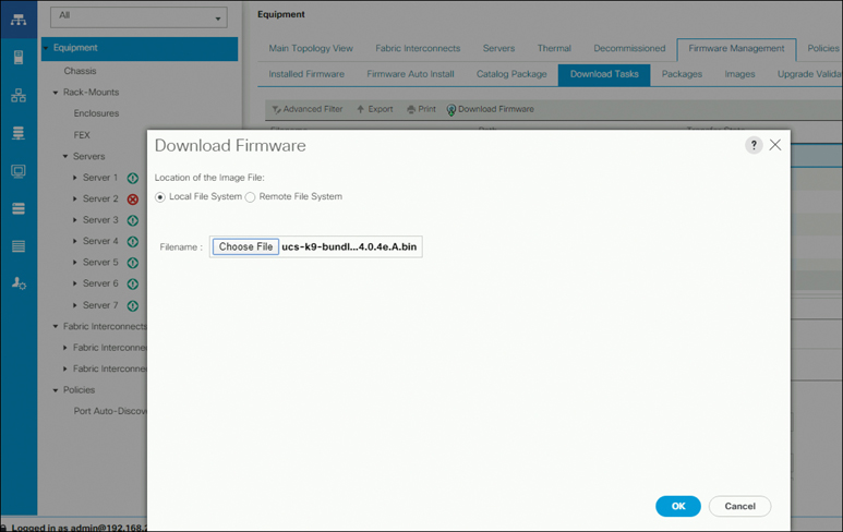
Figure 5-45 Downloading UCS Software Packages on UCSM
Note
Download the UCS-B Series bundle and upload it to UCSM even if you don’t have compute blades. This is a prerequisite for UCS Firmware Upgrade.
Verifying the Pre-Upgrade UCS Server Firmware (C-Bundle) Version
Before performing the upgrade, you need to verify the current UCS server firmware by using one of the two methods described in the sections that follow.
Using UCS Manager
Using Cisco UCS Manager to verify the current UCS server firmware, follow these steps:
Step 1. Log in to UCS Manager.
Step 2. Select the Server tab.
Step 3. Select the host firmware package policy by navigating to Policies > Root > Sub-Organizations > <hx-cluster> > Host Firmware Packages > HyperFlex.
Step 4. Under properties, note the current rack package version, which should be listed as X.Y(Z)C. For example, Figure 5-46 shows version 4.0(2d)C.
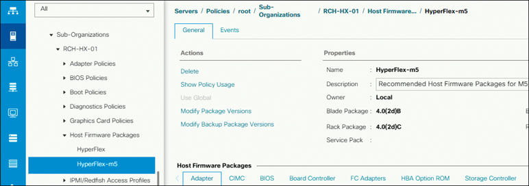
Figure 5-46 Verifying the Server Firmware Version
Using HX Connect
Using Cisco Hyperflex Connect to verify the current UCS server firmware, follow these steps:
Step 1. Log in to HX Connect.
Step 2. In the navigation pane, select Upgrade.
Step 3. Select the UCS Firmware checkbox and click Discover.
Step 4. Note the current C-bundle version displayed. Figure 5-47 shows an example where the current server firmware is 4.0(2d).
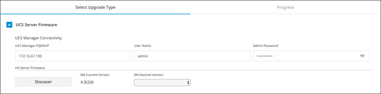
Figure 5-47 Verifying the Server Firmware: HX Connects
Pre-Upgrade Validation
This section lists the checks that are part of the HyperFlex pre-upgrade validations. Perform the following validations (which are all described in more detail in the sections that follow) on each HyperFlex node before moving on to upgrade the next node in the cluster:
Verify that the HyperFlex cluster is healthy and online. Verify that all HyperFlex cluster nodes are connected to vCenter and are online.
Verify the cluster storage capacity.
Verify that DRS is enabled and set to fully automated.
Verifying the Net.TeamPolicyUpDelay default value.
Verify that vSphere services are running and the ESXi Agent Manager (EAM) health is normal.
Verify the health of the cluster in Cisco UCS Manager.
Verify the vMotion interface.
Verify upstream network connectivity.
Configure the cluster access policy in lenient mode.
Verify that no major alarms are reported for the HyperFlex cluster in HyperFlex Connect.
Viewing the HyperFlex Cluster Health
From HyperFlex Connect, select System Information > Nodes page. Verify if the HyperFlex cluster is healthy and online.
From the vSphere Web Client navigator, select vCenter Global Inventory Lists > Cisco HyperFlex Systems > Cisco HX Data Platform > cluster > Summary. View the cluster widget to verify if the HyperFlex cluster is healthy and online.
Verify whether all HX cluster nodes are connected to the vCenter and whether they are online.
Note
HyperFlex cluster health verification check is automatically performed by Hypercheck utility.
Checking the Cluster Storage Capacity
It is recommended that you check the cluster storage capacity before starting the upgrade of an existing installation of Cisco HX Data Platform. If the storage cluster capacity is above 70%, it is highly recommended to either reduce the amount of storage capacity used or increase the storage capacity by adding new nodes or disks. This confirmation of cluster storage capacity is important because if a node goes down in such a situation, the cluster will not be able to rebalance and will stay unhealthy (online).
Note
Cluster storage capacity (enospace) verification check is automatically performed by the Hypercheck utility.
Verifying That DRS Is Enabled
Follow these steps to ensure that DRS is enabled on the node:
Step 1. From the vSphere Web Client navigator, select vCenter Inventory Lists > Clusters > cluster > Configure tab. Verify that DRS is enabled.
Step 2. Click the vSphere DRS tab. Ensure that Migration Automation Level is set to Fully Automated, as shown in Figure 5-48.
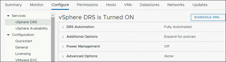
Figure 5-48 DRS Settings: Enabled and Fully Automated
Verifying and Configuring the Net.TeamPolicyUpDelay Default Value
To avoid loss of storage access during fabric interconnect reboots for firmware updates, perform this check prior to UCSM infrastructure upgrade.
Upgrades to 3.5(2) require that the default value of the ESXi host Net.TeamPolicyUpDelay be set to 30000. Complete the following steps to verify and, if needed, modify the default value of the ESXi host Net.TeamPolicyUpDelay to 30000 (see Figure 5-49):
Note
The Net.TeamPolicyUpDelay value check is automatically performed by the Hypercheck utility.
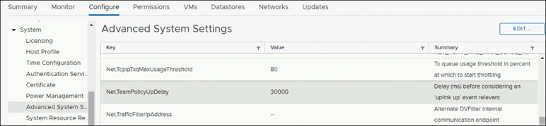
Figure 5-49 Advanced Configuration: Net.TeamPolicyUpDelay
Step 1. From the vSphere Web Client navigator, select ESXi Host > Configure > System > Advanced System Settings.
Step 2. In Advanced System Settings, scroll down to Net.TeamPolicyUpDelay.
Step 3. If needed, change the value to 30000. The default value is 100.
Viewing ESX Agent Manager
From the vSphere Web Client navigator, select Administration > vCenter Server Extensions > vSphere ESX Agent Manager > Configure > ESX Agencies.
Verify that the ESX Agent Manager (EAM) status is normal, as shown in Figure 5-50.
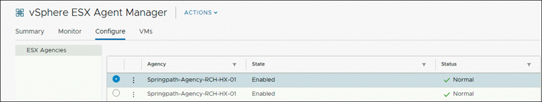
Figure 5-50 EAM Status
Note
Starting with the HX 4.0 release, it is recommended to remove EAM from HyperFlex clusters that are upgraded from older releases. New installations of HX 4.0 do not use EAM.
Verifying the Health of a HyperFlex Cluster in Cisco UCS Manager
Cisco UCS Manager health checks help with verifying the status of the UCS infrastructure and servers before you perform an upgrade. Use the following steps for verification:
Step 1. Verify whether the high availability status of the fabric interconnects shows that both fabric interconnects are up and running. Log in to UCSM and browse to Equipment > Fabric Interconnect > FIA > Expand High Availability Details and verify that the Ready and State fields show Yes and Up, respectively, as shown in Figure 5-51.
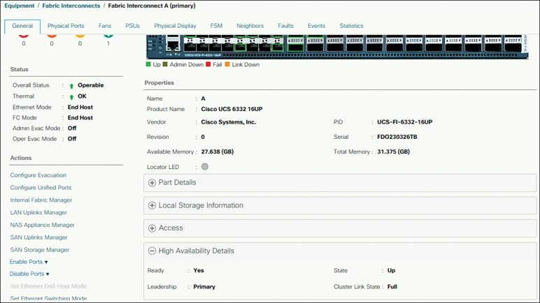
Figure 5-51 High Availability Status
Step 2. Verify that the data path is up and running by entering the following commands:
a. To enter NX-OS mode for the fabric interconnect, enter the following command:
UCS-A /fabric-interconnect # connect nxos {a | b }
b. To determine the number of active Ethernet interfaces, enter the following command:
UCS-A(nxos)# show int br | grep -v down | wc –l
Verify that the number returned matches the number of Ethernet interfaces that were up prior to the upgrade.
c. To determine the total number of MAC addresses, enter the following command:
UCS-A(nxos)# show platform fwm info hw-stm | grep '1.' |
wc –l
Verify that this number matches the number of MAC addresses prior to the upgrade.
See the Cisco UCS Manager Firmware Management Guide (https://www.cisco.com/c/en/us/td/docs/unified_computing/ucs/ucs-manager/GUI-User-Guides/Firmware-Mgmt/3-2/b_UCSM_GUI_Firmware_Management_Guide_3_2.html) for more information.
Step 3. Verify that the HyperFlex servers have no faults that might impact an upgrade. For example, Figure 5-52 shows an example of a HyperFlex server on Cisco UCSM that has status OK and doesn’t have any critical, major, or minor alerts.

Figure 5-52 HyperFlex Server Status and Faults
Verifying vMotion Interfaces
Make sure the vMotion VMkernel interfaces necessary for vMotion to work are configured on each ESXi host. You must predefine vMotion networking by creating a vSwitch switch and defining the vNICs and VLANs in UCS Manager.
Before you perform maintenance operations on a Cisco HyperFlex cluster, you need to verify that all nodes in the HX cluster are configured for vMotion.
Note
You can create vMotion interfaces by using a post_install script. Refer to Chapter 3, “Installing HyperFlex,” for details. The vMotion verification check is automatically performed by the Hypercheck utility.
Verifying Upstream Network Connectivity
You need to ensure that the hx-storage-data and vMotion upstream switches are configured for jumbo frames. Skipping this step could lead to input/output interruption during Cisco UCS infrastructure upgrade. Follow this process:
Step 1. Put a node in Cisco HX maintenance mode.
Step 2. SSH to the ESXi host in step 1.
Step 3. Verify that ping is working by pinging the corresponding vmk1 IP interface of another host.
If using jumbo frames, use the following command:
# vmkping -I vmk1 -d -s 8972 <data IP of address of another
host>
If not using jumbo frames, use the following command:
# vmkping -I vmk1 -d -s 1472 <data IP of address of another
host>
Step 4. Swap the active interfaces in vswitch-hx-storage-data to force traffic upstream:
# esxcli network vswitch standard policy failover set -a
vmnic1 -s vmnic5 -v vswitch-hx-storage-data
Step 5. Again verify that the ping is working by pinging the corresponding vmk1 IP interface of another host.
If using jumbo frames, use the following command:
# vmkping -I vmk1 -d -s 8972 <data IP of address of another
host>
If the ping fails, try again with this command:
# vmkping -I vmk1 -d -s 1472 <data IP of address of another
host>
If not using jumbo frames, use the following command:
# vmkping -I vmk1 -d -s 1472 <data IP of address of another
host>
Note
If the ping fails, do not proceed to upgrade the Cisco UCS firmware. Investigate the network configuration, including the upstream switch, to determine the cause of the failure.
Step 6. Return the interface back to the defaults even if the ping fails:
# esxcli network vswitch standard policy failover set -a
vmnic5 -s vmnic1 -v vswitch-hx-storage-data
Note
vmnic5 and vmnic1 are supported for upgrade from 3.5(x) and later releases of HyperFlex.
Step 7. Exit the node from Cisco HX maintenance mode.
Configuring the Cluster Access Policy in Lenient Mode
The cluster access policy works with the data replication factor to set levels of data protection and data loss prevention. There are two cluster access policy options:
Strict mode: Applies policies to protect against data loss. If nodes or disks in the storage cluster fail, the cluster’s ability to function is affected. If more than one node fails or one node and disk(s) on a different node fail, this is called a simultaneous failure. The strict setting helps protect the data in the event of simultaneous failures.
Lenient mode: Applies policies to support longer storage cluster availability. This is the default.
The mode is not configurable during installation but can be changed after installation and initial storage cluster configuration.
To modify the cluster access policy to lenient, use the following procedure:
Step 1. SSH to any one of the controller VMs and log in as root.
Step 2. Check whether lenient mode is already configured:
#stcli cluster get-cluster-access-policy
Step 3. If the mode is set to strict, change it to lenient:
#stcli cluster set-cluster-access-policy --name lenient
If it is already set to lenient, no further action is required.
Step 4. Confirm the change:
# stcli cluster info | grep -i policy
Verifying That No Major Alarms Are Reported for the HyperFlex Cluster in HyperFlex Connect
Log in to HX Connect and browse to Alarms and, verify that there are major alarms, as shown in Figure 5-53.
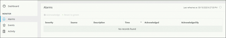
Figure 5-53 HyperFlex Connect: No Major Alarms
Hypercheck Utility
The Hypercheck tool is a utility to perform proactive checks on HyperFlex systems to ensure its stability and resiliency. It provides an automated list of health and pre-upgrade checks on HyperFlex systems to save time during HyperFlex upgrade and maintenance operations.
Cisco recommends running the proactive Hypercheck health check utility on a HyperFlex cluster prior to upgrade. Such checks provide early visibility into any areas that may need attention and will help ensure a seamless upgrade experience.
Note
Most of the health check and pre-validation/pre-upgrade checks on HyperFlex Data Platform are included as a part of the Hypercheck utility and are automatically performed when you run Hypercheck on HyperFlex.
The Hypercheck utility was developed by Cisco CX engineers who troubleshoot HyperFlex every day. It is hosted on the CiscoDevNet GitHub repository and is updated regularly whenever Cisco CX identifies a new check (https://github.com/CiscoDevNet/Hyperflex-Hypercheck).
Storage Controller VM and ESXi Node Checks
Hypercheck performs the following checks on each storage controller VM:
Cluster services check: Verifies the status of the storfs, stMgr, and stNodeMgr services.
Enospc state check: Checks whether the cluster space usage is above the warning threshold.
Zookeeper check: Checks whether Zookeeper is running.
Exhibitor check: Verifies the status of the Exhibitor service, which manages Zookeeper.
HDD health check: Reports if there is any blacklisted disk in a cluster.
DNS check: Checks whether DNS is configured and reachable.
vCenter reachability check: Checks whether vCenter is reachable on the required ports.
Timestamp check: Checks whether all the controller VMs have exactly the same time.
NTP sync check: Checks whether NTP is reachable from the storage controller VMs.
Check package and versions: Checks for packages and versions on controller VMs.
Check iptables count: Compares Iptables counts on all controller VMs.
Cluster upgrade check: Checks whether there are any previous stale upgrade entries.
Extra pnodes check: Looks for any extra/duplicate pnode entries in the cluster.
Disk usage (/var/stv) check: Checks whether the utilization of /var/stv is more than 80%.
Disk usage (/var/zookeeper) check: Checks the utilization of /var/zookeeper.
Out of memory check: Checks through the log files if the cluster had any out-of-memory events.
Supported vSphere check: Lists supported vSphere Versions with current HX Data Platform version.
Network checks: Checks the connectivity between the management and storage networks.
Hypercheck performs the following checks on each ESXi node:
HX user account check: Verifies whether hxuser is on all the hosts and has admin rights.
vMotion enabled check: Checks whether the vMotion network is configured.
vMotion reachability check: Checks the connectivity between vMotion networks.
Check for ESXI failback timer: Checks for the ESXi failback timer on ESXi hosts.
Network check: Sends a ping to vmk0, eth0, and eth1 (between the management and storage networks).
Dumpfile in springpathDS: Checks whether SpringpathDS is configured for a coredump.
VMware tools location check: Checks for VMWare tools location if it was modified from default.
Installing and Running Hypercheck
To install and run Hypercheck, perform the following steps:
Step 1. Download HyperFlex-Hypercheck.zip from https://github.com/CiscoDevNet/HyperFlex-Hypercheck, as shown in Figure 5-54.

Figure 5-54 Downloading Hypercheck Zip
Note
Use only the script downloaded from the CiscoDevNet GitHub account.
Always download the latest version of the tool before you use it. This tool is enhanced frequently, and using older version might result in missing important checks.
Step 2. Upload the tool to the Storage Controller VM (SCVM) with the Cluster Management IP (CMIP). Use your preferred method (scp/sftp/ftp/tftp) to copy the HyperFlex-Hypercheck.zip to the /tmp directory.
Step 3. Extract the contents of HyperFlex-Hypercheck.zip:
a. Type cd /tmp to change to the /tmp directory:
root@SpringpathController7PVQWP6WV1:~# cd /tmp/
b. Type unzip HyperFlex-Hypercheck.zip to extract the files:
root@SpringpathController7PVQWP6WV1:/tmp# unzip
HyperFlex-Hypercheck.zip

Archive:  HyperFlex-Hypercheck.zip
b61c59f7962b72902692ce70548ba3d760efdf06
   creating: HyperFlex-Hypercheck/
  inflating: HyperFlex-Hypercheck/HXTool.py
  inflating: HyperFlex-Hypercheck/LICENSE.txt
  inflating: HyperFlex-Hypercheck/ReadMe.txt
  inflating: HyperFlex-Hypercheck/TestInfo.txt
  inflating: HyperFlex-Hypercheck/prettytable.py
  inflating: HyperFlex-Hypercheck/progressbar.py
root@SpringpathController7PVQWP6WV1:/tmp#
Step 4. Execute the HXTool Python script:
a. Type cd HyperFlex-Hypercheck to go to the HyperFlex-Hypercheck directory:
root@SpringpathControllerABCDE01234:/tmp# cd HyperFlex-
Hypercheck
b. Type python HXTool.py to execute the script and provide the root passwords for the controller VM and ESX:
root@SpringpathControllerABCDE01234:/tmp/HyperFlex-
Hypercheck# python HXTool.p
              .   HX Health Check 3.8
Please enter below info of HX-Cluster:

Enter the HX-Cluster Root Password:

Enter the ESX Root Password:
The tool then starts the automated checks on HyperFlex and takes around three to five minutes to complete the checks on a four-node cluster (though the duration varies depending on the cluster size).
Note
To stop the script execution, press Ctrl+Z, and it stops immediately.
Example 5-1 shows sample HXTool output from a three-node cluster. It shows the progress bar during the process and gives a binary PASS/FAIL for each of the checks performed. If one or more checks fail, perform the corresponding corrective action or contact Cisco TAC to fix the issue before proceeding with the upgrade process.
Example 5-1 Sample HXTool Output from a Three-Node Cluster
root@SpringpathControllerABCDE01234:/tmp/HyperFlex-Hypercheck# python HXTool.py

                 HX Health Check 3.8

Please enter below info of HX-Cluster:
Enter the HX-Cluster Root Password:
Enter the ESX Root Password:

SSH connection established to HX Node: 10.X.X.79
SSH connection established to HX Node: 10.X.X.80
SSH connection established to HX Node: 10.X.X.81

<Output Truncated ...>

HX Controller: 10.X.X.79
Cluster services check          [########################] PASS
ZooKeeper & Exhibitor check     [########################] PASS
HDD health check                [########################] PASS
Pre-Upgrade Check               [########################] PASS
Network check                   [########################] PASS

<Similar Output Truncated ...>

HX Controller: 10.X.X.79
Test Summary:
+----------------------------------+-----------+----------+
| Name                             | Result    | Comments |
+----------------------------------+-----------+----------+
| Cluster services check           | PASS      |          |
+----------------------------------+-----------+----------+
| Enospc state check               | PASS      |          |
+----------------------------------+-----------+----------+
| Zookeeper check                  | PASS      |          |
+----------------------------------+-----------+----------+
| Exhibitor check                  | PASS      |          |
+----------------------------------+-----------+----------+
| ZooKeeper Disk Usage             | PASS      |          |
+----------------------------------+-----------+----------+
| HDD health check                 | PASS      |          |
+----------------------------------+-----------+----------+
| DNS check                        | PASS      |          |
+----------------------------------+-----------+----------+
| vCenter reachability check       | PASS      |          |
+----------------------------------+-----------+----------+
| Timestamp check                  | PASS      |          |
+----------------------------------+-----------+----------+
| NTP sync check                   | PASS      |          |
+----------------------------------+-----------+----------+
| Check package & versions         | PASS      |          |
+----------------------------------+-----------+----------+
| Check Iptables count             | PASS      |          |
+----------------------------------+-----------+----------+
| Cluster upgrade status           | PASS      |          |
+----------------------------------+-----------+----------+
| Extra pnodes check               | PASS      |          |
+----------------------------------+-----------+----------+
| Memory usage check               | PASS      |          |
+----------------------------------+-----------+----------+
| Incidence of OOM in the log file | PASS      |          |
+----------------------------------+-----------+----------+
| Supported vSphere versions       | 6.0.0-U3  |          |
|                                  | 6.5.0-U1  |          |
|                                  | 6.5.0-U2  |          |
|                                  | 6.5.0-U3  |          |
|                                  | 6.7.0-UGA |          |
|                                  | 6.7.0-U1  |          |
|                                  | 6.7.0-U2  |          |
|                                  | 6.7.0-U3  |          |
+----------------------------------+-----------+----------+
| Check permissions for /tmp       | PASS      |          |
+----------------------------------+-----------+----------+

<Similar Output Truncated ...>

ESX Host: 10.X.X.76
+--------------------------------------+--------+----------+
| Name                                 | Result | Comments |
+--------------------------------------+--------+----------+
| HX User Account check                | PASS   |          |
+--------------------------------------+--------+----------+
| vMotion enabled check                | PASS   |          |
+--------------------------------------+--------+----------+
| vMotion reachability check           | PASS   |          |
+--------------------------------------+--------+----------+
| Check for ESXI Failback timer        | PASS   |          |
+--------------------------------------+--------+----------+
| Check ping to vmk0, eth0, eth1       | PASS   |          |
+--------------------------------------+--------+----------+
| No extra controller vm folders check | PASS   |          |
+--------------------------------------+--------+----------+
| VMware Tools location check          | PASS   |          |
+--------------------------------------+--------+----------+

<Similar Output Truncated ...>

Main Report File: HX_Tool_Main_Report_15-03-2020_05-24-12_.txt
Report tar file: HX_Report_15_03_2020_17_15_17.tar
Report file copied to path: /var/log/springpath

Release Notes:
https://www.cisco.com/c/en/us/support/hyperconverged-systems/HyperFlex-hx-data-
  platform-software/products-release-notes-list.html

Upgrade Guides:
https://www.cisco.com/c/en/us/support/hyperconverged-systems/HyperFlex-hx-data-
  platform-software/products-installation-guides-list.html

Note:
1) Please check the status of Compute nodes manually, script only verifies the
   config on the converged nodes.
2) Hypercheck doesnot perform FAILOVER TEST, so please ensure that the upstream is
   configured for network connectivity for JUMBO or NORMAL MTU size as needed.
Be sure to resolve all the issues identified during the preceding verification process and then proceed to the next step of performing the HyperFlex upgrade procedure.
Upgrading UCS Infrastructure Firmware
This section covers how to upgrade UCS infrastructure firmware. The steps are as follows:
Step 1. Open the UCS Manager GUI.
Step 2. Select Equipment > Firmware Management > Firmware Auto Install.
Step 3. Click Install Infrastructure Firmware (see Figure 5-55). Check the Ignore All box if the warnings are not critical to the user environment and click Next.

Figure 5-55 Firmware Auto Install
Step 4. Select Infra Pack from the drop-down list and click the Upgrade Now box to immediately begin the firmware upgrade. Click Finish.
The Cisco UCS Manager GUI might disconnect. This is expected during a UCS Manager upgrade as UCS Manager is stopped and then restarted at the new version. Wait until UCS Manager goes back online. Log back in to UCS Manager to complete the next steps.
Step 5. Click Finish, and the UCS Manager software upgrades (see Figure 5-56).
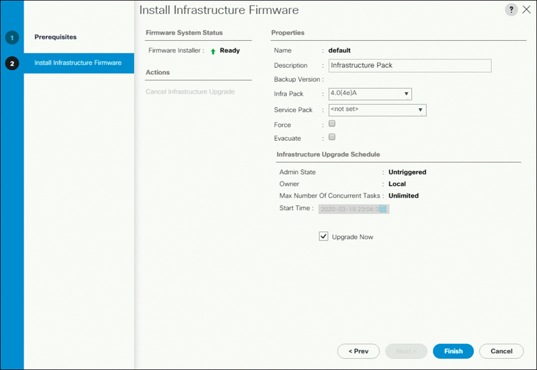
Figure 5-56 Installing the Infrastructure Firmware
Step 6. Log back in to UCS Manager, wait for the subordinate FI to be activated, and then select Equipment > Installed Firmware > Fabric Interconnects.
Step 7. Verify that the subordinate FI has rebooted and joined the UCS cluster:
a. Check the kernel and switch versions of the FI.
b. Ensure that the FI has no fault.
c. Ensure that the FI cluster membership is Subordinate (see Figure 5-57).
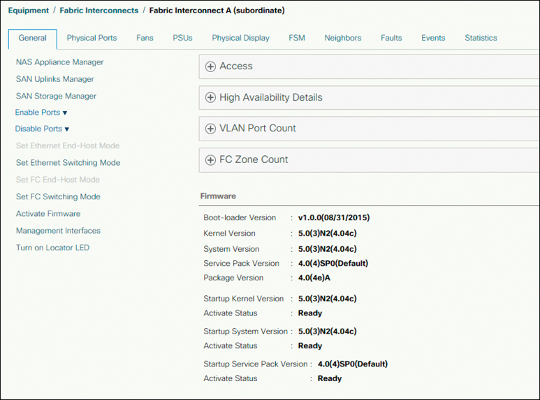
Figure 5-57 Checking the Subordinate FI Version
Step 8. Wait until HX traffic is repinned to both FIs. Wait for UCS Manager vNIC faults to be cleared.
Step 9. Verify that the HX cluster is online and healthy before rebooting the primary fabric interconnect. (Refer to the section “Viewing the HyperFlex Cluster Health,” earlier in this chapter, for more on how to check HX cluster health.)
Step 10. In the UCS Manager GUI, on the toolbar, click Pending Activities (see Figure 5-58). Click the Fabric Interconnects tab to see the tasks requiring user acknowledgment before they can be completed.
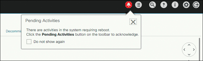
Figure 5-58 Pending Activities
Step 11. Click Reboot now for each pending activity that you want to deploy immediately (see Figure 5-59). Cisco UCS Manager immediately reboots the primary FI.
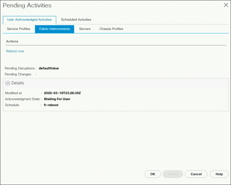
Figure 5-59 Fabric Interconnect: Reboot Now
Step 12. Check the status to determine whether the subordinate FI has become the primary FI.
Step 13. Verify that the FI has rebooted and joined the UCS cluster as the subordinate. Wait until HX traffic is repinned to both FIs.
Step 14. In the UCS manager GUI, wait until all server vNIC faults have been cleared and verify the currently installed infrastructure version (see Figure 5-60).

Figure 5-60 UCS: Installed Firmware
Step 15. Verify that the HX Cluster is online and healthy after rebooting the FI. (For more information on how to check the HX cluster health, see the section “Viewing the HyperFlex Cluster Health,” earlier in this chapter.)
Upgrade Procedure
An upgrade can occur online or offline. Using either of these methods, you can choose to perform any of the following:
Combined upgrade: Combined upgrade means upgrading all three components together: HX Data Platform, UCS, and ESXi.
Split upgrade: Split upgrade means upgrading HX Data Platform first and then upgrading either UCS and/or ESXi. To perform a split upgrade, you must upgrade HX Data Platform first. After HX Data Platform is upgraded to 3.5(1x), you can perform a split upgrade of UCSM only, ESXi only, or both.
Note
The UCS infrastructure is upgraded first in both the combined upgrade and split upgrade processes.
Recommended Upgrade Method
For both the combined upgrade and the split upgrade, Cisco recommends upgrading the HyperFlex components in the following order for optimizing the upgrade time:
Upgrade the Cisco UCS infrastructure.
Upgrade Cisco HX Data Platform.
Upgrade Cisco customized VMware ESXi.
Upgrade the Cisco UCS firmware.
Online Upgrade Process
When using the online upgrade process workflow, consider the following:
First upgrade the Cisco UCS infrastructure to the latest version and then use the automated upgrade workflow for a combined upgrade of Cisco UCS firmware and Cisco HX Data Platform. An online upgrade uses host firmware packages to upgrade all server endpoints.
During an online upgrade, as one node is being upgraded (placed into maintenance mode), the number of tolerated node failures is reduced based on the Data Replication Factor and Access Policy settings.
If upgrading both HX Data Platform and the UCS firmware, a combined upgrade can be selected through HX Connect, depending on the length of the maintenance window.
Note
Do not use the Firefox browser for an online upgrade. It is not supported because it is bundled with an outdated version of Flash.
Online Upgrade Workflow Steps
To do an online upgrade, follow these steps:
Step 1. Download the Cisco UCS infrastructure A, blade bundle B, and rack bundle C on UCSM, as discussed in the section “Downloading UCS Infra, B-Series, C-Series, and Storfs Bundles” earlier in this chapter.
Note
Download the UCS B-Series bundle and upload even if you don’t have compute blades. This is a prerequisite for UCS Firmware Upgrade.
Step 2. Ensure that the hx-storage-data and vMotionupstream switches are configured for full network failover capability. Otherwise, the HyperFlex cluster goes offline, and all datastores unmount from the ESXi hosts. For a reminder of how to perform this check, see the section “Verifying Upstream Network Connectivity,” earlier in this chapter.
Step 3. Upgrade the Cisco UCS infrastructure as required.
Note
It is important that you manually upgrade the UCS infrastructure before initiating the upgrade sequence for the HyperFlex components, as described earlier in this chapter, in the section “Upgrading UCS Infrastructure Firmware.” The upgrade feature of the HX Platform software will not upgrade the UCS infrastructure bundle. This upgrade is a separate process (Auto Install) that can be performed from UCSM.
Step 4. Disable the snapshot schedule by using the command stcli snapshot-schedule --disable.
Step 5. Initiate the upgrade from the HX Connect UI, as discussed in the next section.
Step 6. Confirm that the upgrade task is complete.
Step 7. Enable the snapshot schedule by using the command stcli snapshot-schedule --enable.
Upgrading a HyperFlex Cluster Using the HX Connect UI
To upgrade a HyperFlex cluster using the HX Connect UI, follow these steps:
Step 1. Use Auto Bootstrap and Upgrading Management Packages to upgrade Cisco HX Data Platform. Log in to HX Connect, navigate to https://<storage- cluster-management-ip>, enter the administrative username and password, and click Login.
Step 2. In the navigation pane, select Upgrade. The Select Upgrade Type page appears, as shown in Figure 5-61.
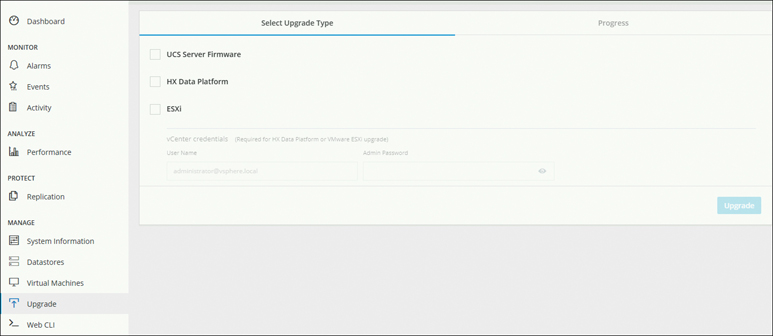
Figure 5-61 Selecting the Upgrade Type in HyperFlex Connect
Step 3. Upload the new Cisco HX Data Platform upgrade package, enter your vCenter credentials, as illustrated in Figure 5-62 and Figure 5-63, and then click Upgrade.
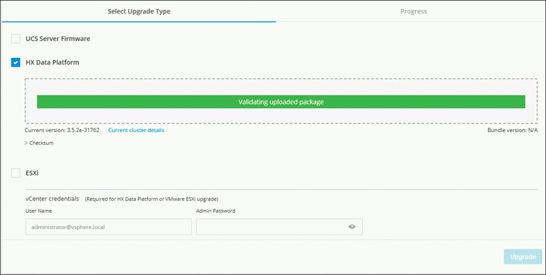
Figure 5-62 Uploading the HX Data Platform Upgrade Package: Validation

Figure 5-63 HX Data Platform Upgrade Package: Upload Success
Step 4. In the Initiating Pre-Upgrade message box that appears (see Figure 5-64), click Confirm. The Pre-Upgrade Process auto bootstrapping and updating management plug-in begins to run on all nodes, as shown in Figure 5-65.
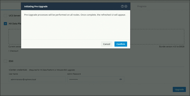
Figure 5-64 Initiating the Pre-Upgrade Process

Figure 5-65 Pre-Upgrade in Progress: Auto Bootstrapping
Step 5. When the Pre-Upgrade process is complete, and the HX Connect UI prompts you with the onscreen message shown in Figure 5-66, click Upgrade again to complete the HX Data Platform part of the upgrade.
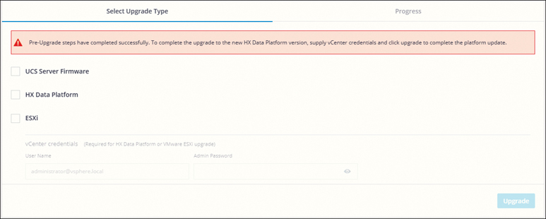
Figure 5-66 Pre-Upgrade Success
Note
The cluster upgrade is not complete until the full upgrade is initiated. The upgrade is only partially complete after the pre-upgrade auto bootstrapping steps (steps 1 through 5).
Step 6. Choose the type of upgrade from the Select Upgrade Type page:
HX Data Platform and UCS Server Firmware
HX Data Platform and ESXi
HX Data Platform, UCS Server Firmware, and ESXi
Step 7. Depending on the type of upgrade you want to perform, complete the following fields on the Select Upgrade Type page(see Figure 5-67):
UCS Server Firmware:
In the UCS Manager FQDN/IP field, enter the Cisco UCS Manager FQDN or IP address.
In the User Name field, enter the Cisco UCS Manager <admin> username.
In the Admin Password field, enter the Cisco UCS Manager <admin> password.
Click the Discover button to view the current UCS firmware package version (which is listed under M5 Current Version).
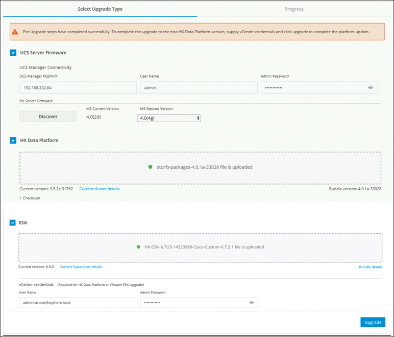
Figure 5-67 Uploading Upgrade Bundles
Data Platform:
Upload the Cisco HyperFlex Data Platform upgrade bundle for upgrading existing clusters (the one used in Step 3).
Notice that the current HyperFlex Data Platform version is displayed.
Notice that the HyperFlex Data Platform version of the uploaded bundle is displayed.
ESXi:
Upload the latest Cisco HyperFlex custom image offline bundle for upgrading existing ESXi hosts (for example, HX-ESXi-6.7U3-14320388-Cisco-Custom-6.7.3.1-upgrade-bundle.zip).
Notice that the current ESXi version is displayed.
Notice that the ESXi version of the uploaded bundle is displayed.
When you’re done with the settings in this screen, click Upgrade to begin the cluster upgrade process. The validation screen on the Progress page shows the progress of the checks performed (see Figure 5-68).
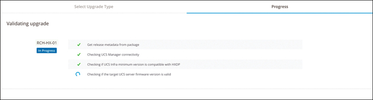
Figure 5-68 Validating the Upgrade
When the validations are complete, the upgrade process starts, and the Progress page displays the upgrade progress for all the nodes (see Figure 5-69).
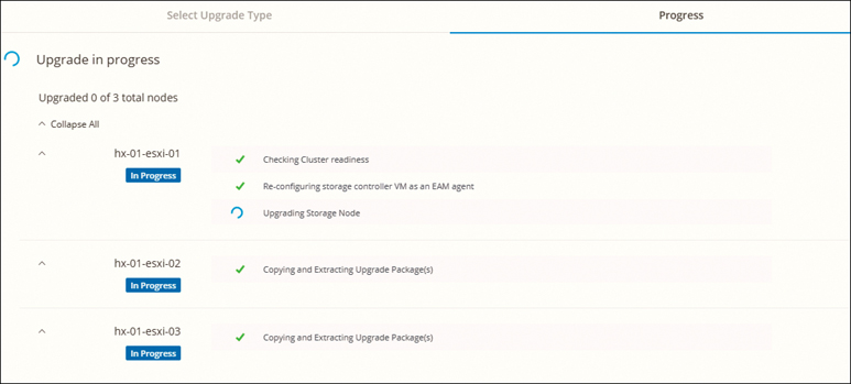
Figure 5-69 Upgrade Progress
When the upgrade completes, the Progress page shows that the HX Data Platform upgrade has completed and asks you to refresh the browser session to see the upgrade changes (see Figure 5-70).
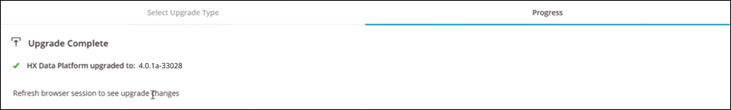
Figure 5-70 Upgrade Complete
Offline Upgrade Process
Before you proceed with either a combined upgrade or a split upgrade, consider the following guidelines:
The package name must match the file that you uploaded to the controller VM.
You need to enter passwords when prompted to do so.
Nodes are upgraded with the new version of the Cisco HX Data Platform software and rebooted one at a time.
Offline cluster upgrades with nested vCenter are not supported.
The steps for an offline upgrade are as follows:
Step 1. Download Cisco UCS infrastructure A, blade bundle B, and rack bundle C on UCSM.
Step 2. Ensure that the hx-storage-data and vMotionupstream switches are configured for full network failover capability.
Step 3. Upgrade the Cisco UCS infrastructure as required (manually).
Step 4. Perform a graceful shutdown of an HX cluster (SCVMs must remain powered on):
a. SSH to any controller VM in the cluster.
b. Check the cluster health by using the command stcli cluster info | grep health.
c. If the cluster is healthy, shut down the cluster with the command stcli cluster shutdown.
d. Wait a few minutes for the shutdown to complete and the prompt to return.
Step 5. Disable the snapshot schedule by using the command stcli snapshot-schedule --disable.
Step 6. Do a manual bootstrap upgrade by copying storfs-package to /tmp and confirming the plug-in version on vCenter. Run the cluster bootstrap script from the node that has the Cluster Management IP. Bootstrap is a process to update the management packages and plugin on vCenter, as in the example as shown here:
# tar –zxvf storfs-packages-4.0.1a-33028.tgz
#./cluster-bootstrap.sh
Note
Copy storfs-packages-<>.tgz into /tmp. Do not use any folder other than /tmp and do not create any subfolders
Step 7. Do an offline upgrade using CLI. The following is an example of a combined upgrade for M5 servers:
# stcli cluster upgrade --components ucs-fw, hxdp, hypervisor
--location /tmp/storfs-packages-3.5.1a-19712.tgz --ucsm-host
eng-fi16.eng.storvisor.com --ucsm-user admin --ucs5fw-version
'3.1(2g)'
Step 8. When the upgrade is complete, start the cluster and power on the VMs by following these steps:
a. Log in to any controller VM through SSH by using the command stcli cluster start, as in this example:
root@SpringpathControllerZRVF040451# stcli cluster
upgrade-status
Cluster upgrade succeeded

root@SpringpathControllerZRVF040451# stcli cluster start
waiting for Cluster to start on nodes:
This will start the cluster and mount the HX datastores.
Wait for cluster to come online.
Cluster is online
b. Wait for the cluster to become healthy before starting the VMs. Then run the command stcli cluster info| grep health, as in this example:
root@SpringpathControllerZRVF040451# stcli cluster info |
grep health
healthState: healthy
state: healthy
 storage cluster is healthy
c. When the cluster is healthy, launch vSphere Web Client or Thick Client, navigate to Hosts and Cluster > Datacenter, right-click Cluster, and select Power > Power On to start the VMs.
Step 9. Enable the snapshot schedule by using the command stcli snapshot-schedule --enable.
Post-Upgrade Check
After a cluster is upgraded, you can do the following to confirm the cluster state after upgrade:
Log in to HyperFlex Connect and confirm the cluster health and cluster version.
Rerun Hypercheck to perform a health check of the cluster.
Summary
This chapter covers important Day 2 operations on HyperFlex, including the following topics:
HyperFlex licensing
Virtual machine management
Scaling HyperFlex clusters
Hardware (disk) replacement
HyperFlex software upgrades