Chapter 3
Installing HyperFlex
This chapter covers the details of installing the various types of HyperFlex clusters. It includes information about prerequisites and various components needed to install a Cisco HyperFlex cluster.
A Cisco HyperFlex HX-Series system provides a fully contained virtual server platform that combines all three layers of compute, storage, and network with the powerful Cisco HX Data Platform software tool, resulting in a single point of connectivity for simplified management.
As discussed in Chapter 2, “HyperFlex Architecture,” there are three types of HyperFlex clusters:
Cisco HyperFlex standard cluster: Cisco Hyperflex standard cluster is deployed under a single UCS management domain with minimum 3 HX Nodes which form a cluster. The hyperFlex nodes have configurable processor, memory, drive, power, interconnect and accessory options.
Cisco HyperFlex edge cluster or ROBO (Remote Office Branch Office) sclusters: Cisco HyperFlex Edge solutions are deployed as fixed sets of two, three, or four nodes that use existing Gigabit Ethernet and 10 Gigabit Ethernet switches, offering the utmost in flexibility for deployment in remote office/branch office (ROBO) environments.
Cisco HyperFlex stretch cluster: A HyperFlex cluster can reside in a single location, or it can be stretched across short geographic distances. An active/active stretch cluster synchronously replicates data between the two sites and has a very short recovery time objective (RTO) and zero data loss. Across longer geographic distances, native replication can synchronize data from a primary site to a secondary site to support more traditional disaster recovery strategies. HyperFlex also supports stretch clusters, where one cluster can span multiple locations. Each location requires a pair of fabric interconnects.
Installation can be performed using the on-premises installer VM or Cisco Intersight.
Note
At the time of writing this book, stretch clusters cannot be deployed from Intersight.
Intersight is a platform that provides IT infrastructure management as a service. Intersight is based on a microservice architecture and is delivered as a cloud-native or on-premises solution. Refer to Chapter 7, “Deploying HyperFlex Anywhere with Intersight,” for information on HyperFlex installation using Intersight.
This chapter covers the installation of all three types of HyperFlex clusters for the ESXi hypervisor.
Note
All screenshots in this chapter show HyperFlex version 3.5.
The following section describes the installation and configuration requirements for the Cisco HyperFlex systems.
Installation Prerequisites
Before a HyperFlex installation, it is important to prepare and configure the following components:
Cisco UCS (servers, fabric interconnects, and so on)
Network
Hypervisor
DNS server
NTP server
SMTP server
vCenter
The topology in Figure 3-1 shows how all these components come together in a HyperFlex implementation.

Figure 3-1 Network Topology for a HyperFlex Implementation
The following sections provide details on the prerequisites and configuration of the various components.
Cisco HyperFlex HX-Series System Components
These HX System components comprise the Cisco HX Series server and Cisco HX Data Platform.
Cisco HX-Series server: You can use any of the following servers to configure Cisco HyperFlex:
Converged nodes—All Flash: Cisco HyperFlex HXAF240c M5, HXAF220c M5, HXAF240c M4, and HXAF220c M4.
Converged nodes—Hybrid: Cisco HyperFlex HX240c M5, HX220c M5, HX240c M4, and HX220c M4.
Compute-only—Cisco B200 M3/M4, B260 M4, B420 M4, B460 M4, B480 M5, C240 M3/M4, C220 M3/M4, C480 M5, C460 M4, B200 M5, C220 M5, and C240 M5.
Note
A converged node provides storage and compute resources to the cluster, whereas a compute-only node provides compute resources to the cluster only.
Cisco HX Data Platform: The HX Data Platform consists of the following components:
Cisco HX Data Platform installer: Download this installer to a server connected to the storage cluster. The HX Data Platform installer configures the service profiles and policies within Cisco UCS Manager, deploys the controller VMs, installs the software, creates the storage cluster, and updates the VMware vCenter plug-in.
Storage controller VM: Use the HX Data Platform installer to install the storage controller VM on each converged node in the managed storage cluster.
Cisco HX Data Platform plug-in: This integrated VMware vSphere interface monitors and manages the storage in a storage cluster.
Cisco UCS Fabric Interconnects (FIs)
Fabric interconnects provide both network connectivity and management capabilities to any attached Cisco HX-Series server.
FIs that were purchased and deployed as part of the Cisco HyperFlex system are also referred to as the HX FI domain in this chapter. The following fabric interconnects are supported:
Cisco UCS 6200 Series fabric interconnects
Cisco UCS 6300 Series fabric interconnects
Cisco UCS 6400 Series fabric interconnects
Note
UCS FIs are required for standard and stretch clusters. Edge clusters do not need UCS FIs.
Cisco Nexus Switches
Cisco Nexus switches deliver high-density, configurable ports for flexible access deployment and migration.
HyperFlex Software Versions
The HX components—Cisco HX Data Platform Installer, Cisco HX Data Platform, and Cisco UCS firmware—are installed on different servers. Verify that the components on the servers used with and within an HX storage cluster are compatible. For more information, visit https://www.cisco.com/c/en/us/support/hyperconverged-systems/hyperflex-hx-data-platform-software/products-release-notes-list.html.
Host Requirements
A Cisco HyperFlex cluster contains a minimum of three converged HyperFlex nodes. There is an option of adding compute-only nodes to provide additional compute power if there is no need for extra storage. Each server in a HyperFlex cluster is also referred as a HyperFlex node. You need to ensure that each node has the correct settings installed and configured before you deploy the storage cluster. For further information, see https://www.cisco.com/c/en/us/support/hyperconverged-systems/hyperflex-hx-series/products-installation-guides-list.html.
Ensure that the following host requirements are met:
Use the same VLAN IDs for all the servers (nodes or hosts) in a cluster.
Use the same administrator login credentials for all the ESXi servers across a storage cluster.
Keep SSH enabled on all ESXi hosts.
Configure DNS and NTP on all servers.
Install and configure VMware vSphere.
Note
VMware vSphere comes preinstalled from the factory on HX servers.
Use a single VIC only for converged nodes or compute-only nodes. Additional VICs or PCIe NICs are not supported.
Disk Requirements
The disk requirements vary between converged nodes and compute-only nodes. To increase the available CPU and memory capacity, you can expand an existing cluster with compute-only nodes as needed. These compute-only nodes provide no increase in storage performance or storage capacity.
Alternatively, adding converged nodes increases the storage performance and storage capacity alongside CPU and memory resources.
Converged Nodes
Servers with only solid-state drives (SSDs) are All Flash servers. Servers with both SSDs and hard-disk drives (HDDs) are hybrid servers.
The following applies to all the disks in a HyperFlex cluster:
All the disks in the storage cluster must have the same amount of storage capacity. All the nodes in the storage cluster must have the same number of disks.
All SSDs must support TRIM and must have TRIM enabled. (TRIM is an Advanced Technology Attachment [ATA] command that enables an operating system to inform a NAND flash SSD which data blocks it can erase because they are no longer in use. The use of TRIM can improve the performance when writing data to SSDs and can increase the life span of an SSD.)
All HDDs can be either SATA or SAS type. All SAS disks in a storage cluster must be in a pass-through mode.
Disk partitions must be removed from SSDs and HDDs. Disks with partitions are ignored and are not added to an HX storage cluster.
Optionally, you can remove or back up existing data on disks. All existing data on a provided disk is overwritten.
Note
New factory servers are shipped with appropriate disk partition settings. Do not remove disk partitions from new factory servers.
Only disks ordered directly from Cisco are supported.
On servers with self-encrypting drives (SEDs), both the cache and persistent storage (capacity) drives must be SED capable. These servers support Data at Rest Encryption (DARE).
All M4 converged nodes have 2 64 GB SD FlexFlash cards in a mirrored configuration with ESX installed. All M5 converged nodes have M.2 SATA SSD with ESXi installed.
Note
Do not mix storage disk types or storage sizes on a server or across a storage cluster. Mixing storage disk types is not supported.
When replacing cache or persistent disks, always use the same type and size as the original disk.
Do not mix any of the persistent drives. Use all HDDs or all SSDs and use the same size drives in a server.
Do not mix hybrid and all flash cache drive types. Use a hybrid cache device on a hybrid server and use an all flash cache device on an all flash server.
Do not mix encrypted and non-encrypted drive types. Use SED hybrid or SED all flash drives. On SED servers, both the cache and persistent drives must be SED type.
All nodes must use the same size and quantity of SSDs. Do not mix SSD types.
Compute-Only Nodes
Storage on compute-only nodes is not included in the cache or capacity of storage clusters.
Note
When adding compute nodes to a HyperFlex cluster, the compute-only service profile template automatically configures it for booting from an SD card. If you are using another form of boot media, update the local disk configuration policy.
Browser Recommendations
Use one of the browsers listed in Table 3-1 to run the listed HyperFlex components. These browsers have been tested and approved. Other browsers might work, but full functionality has not been tested and confirmed.
Table 3-1 Browser Recommendations for HyperFlex
Browser |
Cisco UCS Manager |
HX Data Platform Installer |
HX Connect |
Microsoft Internet Explorer |
9 or higher |
11 or higher |
11 or higher |
Google Chrome |
14 or higher |
56 or higher |
56 or higher |
Mozilla Firefox |
7 or higher |
52 or higher |
52 or higher |
Port Requirements
If your network is behind a firewall, in addition to the standard port requirements, VMware recommends ports for VMware ESXi and VMware vCenter.
Table 3-2 lists the open port requirements in a network between various components (HX Data Platform installer, ESXi, SCVM, vCenter, and so on) for HyperFlex installation and operations:
CIP-M is for the cluster management IP address.
SCVM is the management IP address for the controller VM.
ESXi is the management IP address for the hypervisor.
Table 3-2 Open Port Network Requirements for HyperFlex Installation and Operation
Port Number |
Service/Protocol |
Source |
Port Destinations |
Essential Information |
Time Server-Related Ports |
||||
123 |
NTP/UDP |
Each ESXi node Each SCVM node UCSM |
Time server |
Bidirectional |
HX Data Platform Installer-Related Ports |
||||
22 |
SSH/TCP |
HX Data Platform installer |
Each ESXi node |
Management addresses |
Each SCVM node |
Management addresses |
|||
CIP-M |
Cluster management |
|||
UCSM |
UCSM management addresses |
|||
80 |
HTTPS/TCP |
HX Data Platform installer |
Each ESXi Node |
Management addresses |
Each SCVM Node |
Management addresses |
|||
CIP-M |
Cluster management |
|||
UCSM |
UCSM management addresses |
|||
443 |
HTTPS/TCP |
HX Data Platform installer |
Each ESXi node |
Management addresses |
Each SCVM node |
Management addresses |
|||
CIP-M |
Cluster management |
|||
8089 |
vSphere SDK/TCP |
HX Data Platform installer |
Each ESXi node |
Management addresses |
902 |
Heartbeat/UDP/TCP |
HX Data Platform installer |
vCenter Each ESXi node |
|
None |
Ping/ICMP |
HX Data Platform installer |
ESXi IP addresses CVM IP addresses |
Management addresses |
9333 |
UDP/TCP |
HX Data Platform installer |
CIP-M |
Cluster management |
Mail Server-Related Ports (Optional for Email Subscription to Cluster Events) |
||||
25 |
SMTP/TCP |
Each SCVM node CIP-M UCSM |
Mail server |
Optional |
Monitoring-Related Ports (Optional for Monitoring UCS Infrastructure) |
||||
161 |
SNMP poll/UDP |
Monitoring server |
UCSM |
Optional |
162 |
SNMP trap/UDP |
UCSM |
Monitoring server |
Optional |
Name Server-Related Ports |
||||
53 (external lookups) |
DNS/TCP/UDP |
Each ESXi node |
Name server |
Management addresses |
Each SCVM node |
Name server |
Management addresses |
||
CIP-M |
Name server |
Cluster management |
||
UCSM |
Name server |
|
||
vCenter-Related Ports |
||||
80 |
HTTP/TCP |
vCenter |
Each SCVM node CIP-M |
Bidirectional |
443 |
HTTPS (Plug-in)/TCP |
vCenter |
Each ESXi node Each SCVM node CIP-M |
Bidirectional |
7444 |
HTTPS (VC SSO)/TCP |
vCenter |
Each ESXi node Each SCVM node CIP-M |
Bidirectional |
9443 |
HTTPS (Plug-in)/TCP |
vCenter |
Each ESXi node Each SCVM node CIP-M |
Bidirectional |
5989 |
CIM Server/TCP |
vCenter |
Each ESXi node |
|
9080 |
CIM Server/TCP |
vCenter |
Each ESXi node |
Introduced in ESXi Release 6.5 |
902 |
Heartbeat/TCP/UDP |
vCenter |
Each ESXi node |
This port must be accessible from each host. Installation results in errors if the port is not open from the HX installer to the ESXi hosts. |
User-Related Ports |
||||
22 |
SSH/TCP |
User |
Each ESXi node |
Management addresses |
Each SCVM node |
Management addresses |
|||
CIP-M |
Cluster management |
|||
HX Data Platform installer |
|
|||
UCSM |
UCSM management addresses |
|||
vCenter |
|
|||
SSO server |
|
|||
80 |
HTTP/TCP |
User |
Each SCVM node |
Management addresses |
CIP-M |
Cluster management |
|||
UCSM |
|
|||
HX Data Platform installer |
|
|||
vCenter |
|
|||
443 |
HTTPS/TCP |
User |
Each SCVM node |
|
CIP-M |
|
|||
UCSM |
UCSM management addresses |
|||
HX Data Platform installer |
|
|||
vCenter |
|
|||
7444 |
HTTPS (SSO)/TCP |
User |
vCenter SSO server |
|
9443 |
HTTPS (Plug-in)/TCP |
User |
vCenter |
|
SSO Server Port |
||||
7444 |
HTTPS (SSO)/TCP |
SSO server |
Each ESXi node Each SCVM node CIP-M |
Bidirectional |
Stretch Witness (Required only when deploying HyperFlex Stretch Cluster) |
||||
2181 2888 3888 |
Zookeeper/TCP |
Witness |
Each CVM node |
Bidirectional, management addresses |
8180 |
Exhibitor (Zookeeper life cycle)/TCP |
Witness |
Each CVM node |
Bidirectional, management addresses |
80 |
HTTP/TCP |
Witness |
Each CVM node |
Potential future requirement |
443 |
HTTPS/TCP |
Witness |
Each CVM node |
Potential future requirement |
Replication (Required Only When Configuring Native HX Asynchronous Cluster to Cluster Replication) |
||||
9338 |
Data services manager peer/TCP |
Each CVM node |
Each CVM node |
Bidirectional, include cluster management IP addresses |
3049 |
Replication for CVM/TCP |
Each CVM node |
Each CVM node |
Bidirectional, include cluster management IP addresses |
4049 |
Cluster map/TCP |
Each CVM node |
Each CVM node |
Bidirectional, include cluster management IP addresses |
4059 |
NR NFS/TCP |
Each CVM node |
Each CVM node |
Bidirectional, include cluster management IP addresses |
9098 |
Replication service |
Each CVM node |
Each CVM node |
Bidirectional, include cluster management IP addresses |
8889 |
NR master for coordination/TCP |
Each CVM node |
Each CVM node |
Bidirectional, include cluster management IP addresses |
9350 |
Hypervisor service/TCP |
Each CVM node |
Each CVM node |
Bidirectional, include cluster management IP addresses |
SED Cluster Ports |
||||
443 |
HTTPS |
Each SCVM management IP (including cluster management IP) |
UCSM (fabric A, fabric B, VIP) |
Policy configuration |
5696 |
TLS |
CIMC from each node |
KVM server |
Key exchange |
UCSM-Related Ports |
||||
443 |
Encryption and so on/TCP |
Each CVM node |
CIMC OOB |
Bidirectional for each UCS node |
81 |
KVM/HTTP |
User |
UCSM |
OOB KVM |
743 |
KVM/HTTP |
User |
UCSM |
OOB KVM encrypted |
Miscellaneous Ports |
||||
9350 |
Hypervisor service/TCP |
Each CVM node |
Each CVM node |
Bidirectional, including cluster management IP addresses |
9097 |
CIP-M failover/TCP |
Each CVM node |
Each CVM node |
Bidirectional for each CVM to other CVMs |
111 |
RPC bind/TCP |
Each SCVM node |
Each SCVM node |
CVM outbound to the installer |
8002 |
Installer/TCP |
Each SCVM node |
Installer |
Service Location Protocol |
8080 |
Apache Tomcat/TCP |
Each SCVM node |
Each SCVM node |
stDeploy makes a connection request with stdeploy |
8082 |
Auth service/TCP |
Each SCVM node |
Each SCVM node |
Any request with uri /auth/ |
9335 |
hxRoboControl/TCP |
Each SCVM node |
Each SCVM node |
Robo deployments |
443 |
HTTPS/TCP |
Each CVM Mgmt IP including CIP-M |
UCSM A/B and VIP |
Policy configuration |
5696 |
TLS/TCP |
CIMC from each node |
KMS server |
Key exchange |
8125 |
UDP |
Each SCVM node |
Each SCVM node |
Graphite |
427 |
UDP |
Each SCVM node |
Each SCVM node |
Service Location Protocol |
32768 to 65535 |
UDP |
Each SCVM node |
Each SCVM node |
SCVM outbound communication |
Verify that the firewall ports listed in Table 3-2 are open.
HyperFlex External Connections
Table 3-3 covers the details and requirements for HyperFlex external connections to Intersight, Auto-Support, and the postinstallation script.
Table 3-3 HyperFlex External Connections
External Connection |
Description |
IP Address/FQDN/Ports/Version |
Essential Information |
Intersight device connector |
Supported HX systems are connected to Cisco Intersight through a device connector that is embedded in the management controller of each system. |
HTTPS port number: 443 1.0.5–2084 or later (auto-upgraded by Cisco Intersight) |
All device connectors must properly resolve svc.ucs-connect.com and allow outbound-initiated HTTPS connections on port 443. The current HX installer supports the use of an HTTP proxy. The IP addresses of ESXi management must be reachable from Cisco UCS Manager over all the ports that are listed as being needed from the installer to ESXi management to ensure deployment of ESXi management from Cisco Intersight. |
Auto-Support |
Auto-Support (ASUP) is the alert notification service provided through HX Data Platform. |
SMTP port number: 25 |
Enabling Auto-Support is strongly recommended because ASUP provides historical hardware counters that are valuable in diagnosing future hardware issues, such as a drive failure for a node. |
Postinstallation script |
To complete postinstallation tasks, you can run a postinstallation script on the installer VM. The script pings across all network interfaces (management, vMotion, and storage network) to ensure full fabric availability. The script also validates the correct tagging of VLANs and jumbo frame configurations on the Northbound switch. |
HTTP port number: 80 |
The postinstallation script requires name resolution to http://cs.co/hx-scripts via port 80 (HTTP). |
UCS/Fabric Interconnect Network Provisioning
Prior to setting up a HyperFlex cluster, you need to plan the upstream bandwidth capacity for optimal network traffic management. This ensures that the flow is in steady state, even if there is a component failure or a partial network outage.
By default, the hx-vm-network vSwitch switch is configured as active/active. All other vSwitch switches are configured as active/standby.
Note
For clusters running Catalyst switches upstream to the FIs, set the best-effort quality of service (QoS) MTU to 9216 (under LAN > LAN Cloud > QoS System Class), or failover will fail.
Configuration for HyperFlex 3.5
Figure 3-2 provides an overview of the UCS service profile mapping to vmware vswitch and vmnics. This is configured automatically during HyperFlex installation.
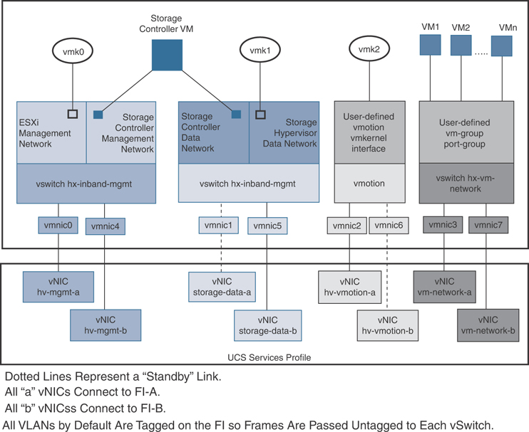
Figure 3-2 HyperFlex Data Platform Connectivity for a Single Host
The default vSwitch NIC teaming policy and failover policy is set to yes to ensure that all management, vMotion, and storage traffic are locally forwarded to the fabric interconnects to keep the flow in steady state. When vNIC-a fails, ESXi computes the load balancing, and all the virtual ports are repinned to vNIC-b. When vNIC-a comes back online, repinning applies, and virtual ports are rebalanced across vNIC-a and vNIC-b. This reduces the latency and bandwidth utilization upstream of the Cisco UCS fabric interconnects. Figure 3-3 shows traffic flow in a normal state when traffic is limited to within the fabric interconnects.
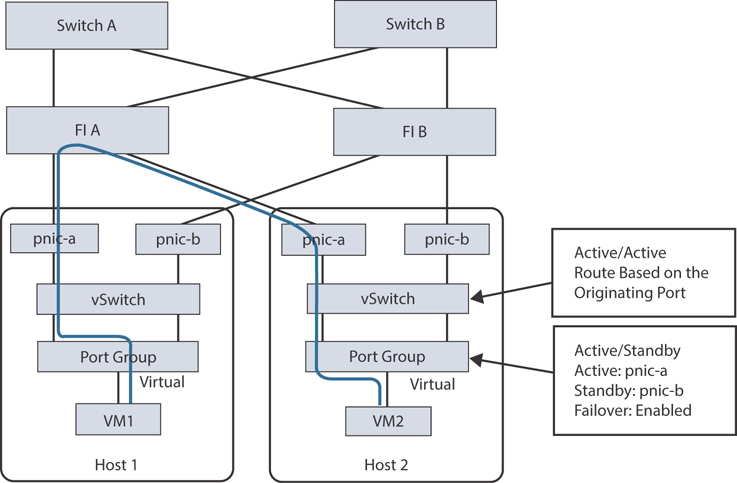
Figure 3-3 Traffic Flow in Steady State
If one or more server links fail—for instance, if Host 1 loses connectivity to fabric A and Host 2 loses connectivity to fabric B—the traffic must go through the upstream switches. Therefore, the uplink network bandwidth usage increases. Figure 3-4 shows traffic flow when an active link failure occurs, resulting in traffic flows through the upstream switch.
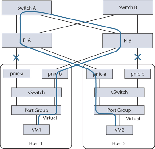
Figure 3-4 Traffic Flow During Link Failure
Note
When you have uplinks from a fabric interconnect to two different upstream switches, you encounter a condition called Disjoint Layer 2 (DJL2) on the FI. This is known to happen on the FI on End Host mode and if the DJL2 is not configured properly.
Network Settings
The following are best practices for UCS and ESXi network configuration when deploying HyperFlex:
Use different subnets and VLANs for each network.
Directly attach each host to a Cisco UCS fabric interconnect using a 10/25/40 Gbps cable.
Do not use VLAN 1, which is the default VLAN, as doing so can cause networking issues, especially if disjoint Layer 2 configuration is used.
For VLANs set as non-native by default, configure the upstream switches to accommodate the non-native VLANs.
Each ESXi host needs the following networks:
Management traffic network: Handles the hypervisor (ESXi server) management and storage cluster management.
Data traffic network: Handles the hypervisor and storage data traffic.
vMotion network: Used for virtual machine vMotion.
VM network: Handles virtual machine network traffic.
There are four vSwitch switches, each carrying a different network:
vswitch-hx-inband-mgmt: Used for ESXi management and storage controller management.
vswitch-hx-storage-data: Used for ESXi storage data and HX Data Platform replication.
vswitch-hx-vmotion: Used for VM and storage vMotion.
vswitch-hx-vm-network: Used for VM data traffic.
Note
The Cisco HX Data Platform installer automatically creates the vSwitch switches. The following services in vSphere must be enabled after the HyperFlex storage cluster is created: DRS (optional, if licensed), vMotion, high availability.
VLAN and vSwitch Requirements
When installing HyperFlex, it is important to provide at least three VLAN IDs. All VLANs must be configured on the fabric interconnects during the installation. Table 3-4 outlines these requirements.
Table 3-4 VLAN and vSwitch Requirements
VLAN Type |
Description |
VLAN ESXi and HyperFlex management traffic* |
VLAN name: hx-inband-mgmt VLAN ID |
VLAN HyperFlex storage traffic* |
VLAN name: hx-storage-data VLAN ID |
VLAN VM vMotion* |
VLAN name: hx-vmotion VLAN ID |
VLAN VM data* |
User defined |
IP blocks |
KVM IP pool One IP address per host |
Subnet mask |
Example: 255.255.0.0 |
Default gateway |
Example: 10.193.0.1 |
* Must use different subnets and VLANs
External Switch Tagging (EST) and vSwitch settings are applied using UCS Manager profiles. The HX Data Platform installer automates and simplifies this process.
Cisco UCS Requirements
When installing HyperFlex, you need to provide information for the UCS fabric interconnect and UCS Manager when prompted, as outlined in Table 3-5 and Table 3-6.
Table 3-5 Cisco UCS Fabric Interconnect Requirements
UI Element |
Essential Information |
Uplink switch model |
Provide the switch type and connection type (SFP + twinax or optic) |
Fabric interconnect cluster IP address |
IP address |
FI-A IP address |
IP address |
FI-B IP address |
IP address |
MAC address pool |
Check 00:00:00 MAC address pool |
IP blocks |
KVM IP pool; a minimum of four IP addresses |
Subnet mask |
Example:255.255.0.0 |
Default gateway |
Example:10.193.0.1 |
Table 3-6 Cisco UCS Manager Requirements
UI Element |
Essential Information |
UCS Manager hostname |
Hostname or IP address |
Username |
Admin username |
Password |
Admin username |
Hypervisor Requirements
When installing HyperFlex, you need to enter the IP address from the range of addresses that are available to the ESXi servers on the storage management network or storage data network through vCenter, as shown in Table 3-7. Provide static IP addresses for all network addresses.
Table 3-7 HyperFlex IP Address Requirements (Example 4 Node HX Cluster)*
Management Network IP Addresses |
Data Network IP Addresses |
||
Hypervisor |
Storage Controller |
Hypervisor |
Storage Controller |
IP address |
IP address |
IP address |
IP address |
IP address |
IP address |
IP address |
IP address |
IP address |
IP address |
IP address |
IP address |
IP address |
IP address |
IP address |
IP address |
VLAN tag |
VLAN_ID |
VLAN tag |
VLAN_ID |
Subnet mask |
|
Subnet mask |
|
Default gateway |
|
Default gateway |
|
Installer Appliance IP Addresses |
|||
IP address |
IP address |
IP address |
IP address |
* Two more IP addresses for virtual IP—one for the management network and one for the data network—are required in addition to the ones listed in this table.
Note
When assigning Ip addresses to Hyperflex Systems, consider the following:
Data and management networks must be on different subnets.
IP addresses cannot be changed after a storage cluster is created. Contact Cisco TAC for assistance if IP address change is required after cluster creation.
If you are specifying DNS names, you should enable forward and reverse DNS lookup for IP addresses.
The installer IP address must be reachable from the management subnet used by the hypervisor and the storage controller VMs. The installer appliance must run on the ESXi host or on a VMware workstation that is not a part of the cluster to be installed.
Storage Cluster Requirements
A storage cluster is a component of the Cisco HX Data Platform that reduces storage complexity by providing a single datastore that is easily provisioned in vSphere Web Client. Data is fully distributed across disks in all the servers that are in the storage cluster to leverage controller resources and provide high availability.
A storage cluster is independent of the associated vCenter cluster. You can create a storage cluster by using ESXi hosts that are in the vCenter cluster.
To define a storage cluster, provide the parameters outlined in Table 3-8.
Table 3-8 Definition of Storage Cluster Parameters
Field |
Description |
Name |
Enter a name for the storage cluster. |
Management IP address |
This is the address of the storage management network for access on each ESXi host. The IP address must be on the same subnet as the management IP addresses for the nodes. Do not allow cluster management IP addresses to share the last octet with another cluster on the same subnet. These IP addresses are in addition to the four IP addresses assigned to the nodes in the previous section. |
Storage cluster data IP address |
This is the address of the storage data network and storage controller VM network for access on each ESXi host. The same IP address must be applied to all ESXi nodes in the cluster. |
Data replication factor |
This is the number of redundant replicas of the data across the storage cluster. This is set during HX Data Platform installation and cannot be changed. The choices are:
If nodes or disks in the storage cluster fail, the cluster’s ability to function is affected. Failure of more than one node or of one node and a disk(s) on a different node is called a simultaneous failure. |
vCenter Configuration Requirements
Configuration of vCenter requires an administrator-level account and password. Ensure that you have an existing vCenter server and also ensure that the following vSphere services are operational:
Enable Dynamic Resource Scheduler (DRS), if licensed (optional)
Enable vMotion
Enable high availability (required to define failover capacity and for expanding the datastore heartbeat)
Ensure that user VMs are version 9 or later (required to use HX Data Platform, native snapshots, and ReadyClones
Table 3-9 outlines the vCenter information required to complete the HyperFlex installation.
Table 3-9 vCenter Requirements for HyperFlex Installation
Field |
Description |
vCenter Server |
Enter your current vCenter server web address. For example, http://<IP address>. |
Username |
Enter <admin username>. |
Password |
Enter <admin password>. |
Data center name* |
Enter the required name for the vCenter data center. |
Cluster name |
Enter the required name for the vCenter cluster. The cluster must contain a minimum of three ESXi servers. |
* An existing data center object can be used. If the data center doesn’t exist in vCenter, it will be created.
System Services Requirements
Before installing Cisco HX Data Platform, ensure that the following network connections and services are operational. Table 3-10 outlines the system services requirements.
Table 3-10 System Services Requirements
Field |
Essential Information |
DNS server(s) |
The DNS server address is required if you are using hostnames while installing the HyperFlex Data Platform. If you do not have a DNS server, do not enter a hostname under System Services in the Cluster Configuration page of the HX Data Platform installer. Use only IP addresses. To provide more than one DNS servers address, separate the addresses with commas. Check carefully to ensure that DNS server addresses are entered correctly. |
NTP server(s) (which must be a reliable NTP server) |
Set the IP address. The NTP server is used for clock synchronization between the storage controller VM, the ESXi hosts, and the vCenter server. A static IP address for an NTP server is required to ensure clock synchronization between the storage controller VM, ESXi hosts, and vCenter server. During installation, this information is propagated to all the storage controller VMs and corresponding hosts. The servers are automatically synchronized on storage cluster startup. |
Time zone |
Select a time zone for the storage controller VMs. The time zone is used to determine when to take scheduled snapshots. Note that all the VMs must be in the same time zone. |
Note
Before configuring the storage cluster, manually verify that the NTP server is working and providing a reliable source for the time. Use the same NTP server for all nodes (both converged and compute) and all storage controller VMs. The NTP server must be stable, continuous (for the lifetime of the cluster), and reachable through a static IP address.
If you are using Active Directory as an NTP server, please make sure that the NTP server is set up according to Microsoft best practices. For more information, see https://docs.microsoft.com/en-us/windows-server/networking/windows-time-service/windows-timeservice-tools-and-settings. Note that if the NTP server is not set correctly, time sync may not work, and you may need to fix the time sync on the client side. For more information, see https://kb.vmware.com/s/article/1035833.
CPU Resource Reservation for Controller VMs
As the storage controller VMs provide critical functionality for the HyperFlex Data Platform, the HX Data Platform installer configures CPU resource reservations for the controller VMs. This reservation guarantees that the controller VMs have the minimum required CPU resources. This is useful in situations where the physical CPU resources of the ESXi hypervisor host are heavily consumed by the guest VMs. Table 3-11 details the CPU resource reservation for storage controller VMs.
Table 3-11 CPU Resource Reservation for Storage Controller VMs
Number of VM CPU |
Shares |
Reservation |
Limit |
8 |
Low |
10,800 MHz |
Unlimited |
Memory Resource Reservation for Controller Virtual Machines
Table 3-12 details the memory resource reservations for the storage controller VMs.
Table 3-12 Memory Resource Reservations for Storage Controller VMs
Server Model |
Amount of Guest Memory |
Reserve All Guest Memory? |
HX220c-M4/M5s HXAF220C-M4/M5s |
48 GB |
Yes |
HX240c-M4/M5SX HXAF240C-M4/M5SX |
72 GB |
Yes |
HX240C-M5L |
78 GB |
Yes |
The compute only nodes, for example, the B200 blades, have a lightweight storage controller VM that is configured with only 1 vCPU and 512 MB of memory reservation.
Controller VM Locations
The physical storage locations of the controller VMs differs among the Cisco HX-Series rack servers due to differences in the physical disk locations and connections on those server models. The storage controller VM is operationally no different from any other typical virtual machines in an ESXi environment. The VM must have a virtual disk with the bootable root file system available in a location separate from the SAS HBA that the VM is controlling via VMDirectPath I/O. The configuration details of the models are as follows:
HX220c M5, HXAF220c M5, HX240c M5, and HXAF240c M5: The server boots the ESXi hypervisor from the internal M.2 form factor SSD. The M.2 SSD is partitioned by the ESXi installer, and the remaining 216 GB of space is used as a VMFS datastore. The controller VM’s root file system is stored on a 2.5 GB virtual disk, /dev/sda, which is placed on this VMFS datastore. The controller VM has full control of all the front- and rear-facing hot-swappable disks via PCI passthrough control of the SAS HBA. The controller VM operating system sees the 240 GB SSD (also commonly called the “housekeeping” disk) as /dev/sdb and places HyperFlex binaries and logs on this disk. The remaining disks seen by the controller VM OS are used by the HX distributed file system for caching and capacity layers. Figure 3-5 and Figure 3-6 detail the storage controller VM placement on ESXi hypervisor hosts for these server types.
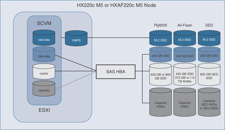
Figure 3-5 HX220c M5 Controller VM Placement
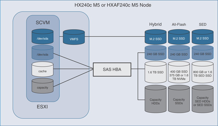
Figure 3-6 HX240c M5 Controller VM Placement
HX220c M4 and HXAF220c M4: The server boots the ESXi hypervisor from the internal mirrored SD cards. The SD card is partitioned by the ESXi installer, and the remaining space is used as a VMFS datastore. The controller VM’s root file system is stored on a 2.5 GB virtual disk, /dev/sda, which is placed on this VMFS datastore. The controller VM has full control of all the front-facing hot-swappable disks via PCI passthrough control of the SAS HBA. The controller VM operating system sees the 120 GB or 240 GB SSD (also commonly called the “housekeeping” disk) as /dev/sdb and places HyperFlex binaries and logs on this disk. The remaining disks seen by the controller VM OS are used by the HX distributed file system for caching and capacity layers. Figure 3-7 details the storage controller VM placement on ESXi hypervisor hosts for these server types.

Figure 3-7 HX220c M4 Controller VM Placement
HX240c M4 and HXAF240c M4: The server boots the ESXi hypervisor from the internal mirrored SD cards. The HX240c-M4SX and HXAF240c-M4SX servers have a built-in SATA controller provided by the Intel Wellsburg Platform Controller Hub (PCH) chip, and the 120 GB or 240 GB housekeeping disk is connected to it, placed in an internal drive carrier. Since this model does not connect the housekeeping disk to the SAS HBA, the ESXi hypervisor remains in control of this disk, and a VMFS datastore is provisioned there, using the entire disk. On this VMFS datastore, a 2.2 GB virtual disk is created and used by the controller VM as /dev/sda for the root file system, and an 87 GB virtual disk is created and used by the controller VM as /dev/sdb, placing the HyperFlex binaries and logs on this disk. The front-facing hot-swappable disks, seen by the controller VM OS via PCI passthrough control of the SAS HBA, are used by the HX distributed file system for caching and capacity layers. Figure 3-8 details the storage controller VM placement on ESXi hypervisor hosts for these server types.
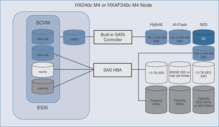
Figure 3-8 HX240c M4 Controller VM Placement
Auto-Support Requirements
Auto-Support (ASUP) is the alert notification service provided through HX Data Platform. If you enable Auto-Support, notifications are sent from HX Data Platform to designated email addresses or email aliases that you want to receive the notifications. To configure Auto-Support, use the information in Table 3-13.
Table 3-13 Required Information for ASUP Configuration
Setting |
Description |
Enable Auto-Support |
Check this box during HX storage cluster creation. |
Mail server |
Set the IP address. The SMTP mail server must be configured in your network to enable Auto-Support. It is used for handling email sent from all the storage controller VM IP addresses. Note that only unauthenticated SMTP is supported for ASUP. |
Mail sender |
Provide the email address to use for sending Auto-Support notifications. |
ASUP recipient |
Specify the list of email addresses or email aliases to receive Auto-Support notifications. |
Note
Enabling Auto-Support is strongly recommended because it provides historical hardware counters that are valuable in diagnosing future hardware issues, such as drive failure for a node.
Single Sign-On Requirements
The single sign-on (SSO) URL is provided by vCenter. If it is not directly reachable from the controller VM, you can configure the location explicitly by using Installer Advanced Settings. The SSO URL can be found in vCenter at vCenter Server > Manage > Advanced Settings, key config.vpxd.sso.sts.uri.
Installing Cisco HyperFlex System Servers
To set up and install the Cisco HyperFlex nodes, refer to the appropriate installation guides. Also set up the fabric interconnects and integrate the HX-Series servers to the Cisco fabric interconnect.
If necessary, refer to Chapter 2, which covers physical installation and topology, before proceeding with the following information.
Physical Connectivity Illustrations for Direct Connect Mode Cluster Setup
Only direct connect mode is supported for HX servers with fabric interconnects. For example, the topologies in Figure 3-9, Figure 3-10, and Figure 3-11 are considered supported. These topologies show a sample of direct connect mode physical connectivity for C-Series rack-mount servers with Cisco UCS Domain and Cisco UCS Manager, release 3.1 or later. These images show the cabling configuration for Cisco UCS Manager integration with a C-Series rack-mount server. The paths shown in these figures carry both management traffic and data traffic.
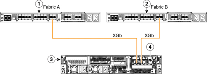
Figure 3-9 Direct Connect Cabling Configuration
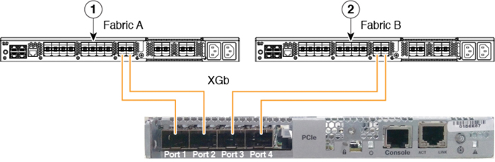
Figure 3-10 Direct Connect Cabling Configuration with Cisco VIC 1455 (Four-Port Linking)

Figure 3-11 Direct Connect Cabling Configuration with Cisco VIC 1455 (Two-Port Linking)
The numbered labels in the preceding figures indicate the following:
Cisco UCS 6454 fabric interconnect or Cisco UCS 6200 Series or 6300 FI (fabric A)
Cisco UCS 6454 fabric interconnect or Cisco UCS 6200 Series or 6300 FI (fabric B)
C-Series rack-mount server
Cisco UCS VIC in supported PCIe slot
In Figures 3-9 and 3-10, XGb represents a 40 Gigabit Ethernet connection or a 10 Gigabit Ethernet connection. For 10 Gigabit Ethernet, the following cables are used:
4x10 breakout Small Form-Factor Pluggable (SFP) cables
4x10 active optical (OAC) cables
10G SFP cable that uses the Qualified Security Assessor (QSA) module
Note
For VIC 1455, the following restrictions apply:
Ports 1 and 2 must connect to same fabric interconnect (that is, fabric A).
Ports 3 and 4 must connect to same fabric interconnect (that is, fabric B).
This is due to the internal port-channeling architecture inside the card. Ports 1 and 3 are used because the connections between ports 1 and 2 (also 3 and 4) form an internal port channel.
Note
The above images show a sample of direct connect mode physical connectivity for C-Series Rack-Mount Server with Cisco UCS VIC 1455. The port connections remain the same for Cisco UCS VIC 1457.
Caution
Do not connect port 1 to Fabric Interconnect A and port 2 to Fabric Interconnect B. Use ports 1 and 3 only. Using ports 1 and 2 results in discovery and configuration failures.
Installation Workflow
The installation workflow illustrated in Figure 3-12 summarizes the steps involved in creating a standard cluster using the HX Data Platform installer:
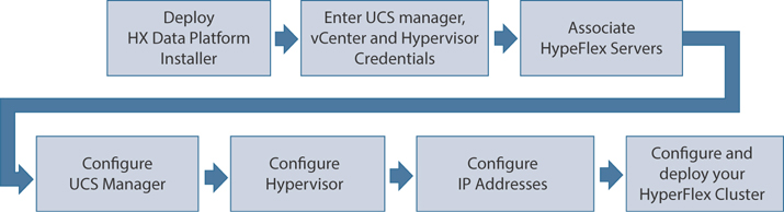
Figure 3-12 HyperFlex Installation Work Flow
Step 1. Deploy the HX Data Platform installer OVA by using the vSphere Web Client.
Step 2. Enter UCS Manager, vCenter, and hypervisor credentials.
Step 3. Configure server ports and associate HyperFlex servers.
Step 4. Configure UCSM (VLANs, MAC pool, hx-ext-mgmt IP oool for out-of-band CIMC, iSCSi storage, FC storage, and so on).
Step 5. Configure the hypervisor.
Step 6. Configure the IP addresses.
Step 7. Configure and deploy the HyperFlex cluster.
The sections that follow cover the steps of this workflow in detail.
Deploy the HX Data Platform Installer OVA by Using the vSphere Web Client
You need to connect to vCenter to deploy the OVA file and provide the IP address properties. Deploying directly from an ESXi host does not allow you to set the values correctly. Do not deploy the HX Data Platform installer to an ESXi server that is going to be a node in the Cisco HX storage cluster.
The procedure for deploying the HX Data Platform installer OVA using vSphere Web Client is as follows:
Step 1. Locate and download the HX Data Platform installer OVA from cisco.com. Download the HX Data Platform installer to a node that is on the storage management network (for example, Cisco-HX-Data-Platform-Installer-v3.5.2e-31762-esx.ova); this node will be used for the HX Data Platform storage cluster.
Step 2. Deploy the HX Data Platform installer by using the VMware hypervisor to create a HX Data Platform installer virtual machine.
Note
Use a version of the virtualization platform that supports virtual hardware version 10.0 or greater. vSphere is a system requirement. You can use either vSphere thick client, vSphere thin client, or vSphere Web Client. To deploy the HX Data Platform installer, you can also use VMware Workstation, VMware Fusion, or VirtualBox. In any case, follow these steps:
Open a virtual machine hypervisor, such as vSphere, VirtualBox, Workstation, or Fusion.
Select the node where you want to deploy the HX Data Platform Installer:
Using vSphere thick client: Expand Inventory list > Host > File > Deploy OVA.
Using vSphere Web Client: Expand vCenter Inventory list > Hosts > Host > Deploy OVA.
Make sure you provide user credentials while deploying the HX installer OVA using vSphere Web Client.
Refer to Figure 3-13 for details.
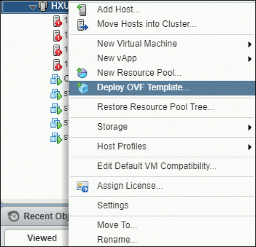
Figure 3-13 Deploying the HX Installer OVA Template
Step 3. Select where the HX Data Platform installer is located. Accept the defaults and select the appropriate network. Then review the details, as shown in Figure 3-14.
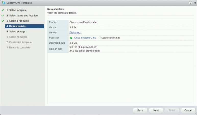
Figure 3-14 Reviewing the Template Details
Step 4. Enter a static IP address for use by the HX Data Platform installer VM, as shown in Figure 3-15. Click Next.
Note
A static IP address is necessary even if DHCP is configured for the network. You need the static IP address to run the HX Data Platform installer, to install the HX Data Platform, and to create the HX Data Platform storage cluster. DNS must be reachable from the installer VM.

Figure 3-15 Customizing the Template Properties
Step 5. In the screen shown in Figure 3-16, verify that the options listed are correct. Click Finish and wait for the HX Data Platform installer VM to be added to the vSphere infrastructure.
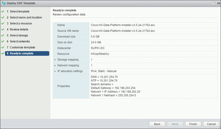
Figure 3-16 Verifying Details and Deploying the HX Installer VM
To power on the HX Data Platform installer manually, navigate to the virtual machine list and power on the installer VM.
Note
The preferred settings for the HX Data Platform installer virtual machine are 3 vCPU and 4 GB of memory. Reducing these settings can result in 100% CPU usage and spikes for the host.
Step 6. Open the HX Data Platform installer virtual machine console and notice that the initial console display lists the HX Data Platform installer virtual machine IP address:
Data Platform Installer.
*******************************************
You can start the installation by visiting
the following URL:
http://192.168.202.20
*******************************************
Cisco-HX-Data-Platform-Installer login:
Step 7. Use the URL listed in the output (for example, http://192.168.202.20) to log in to the HX Data Platform installer.
Step 8. Accept the self-signed certificate.
Step 9. Log in using the username root and the password you provided as part of the OVA deployment.
Note
The default password Cisco123 is no longer valid with HX Data Platform 3.5(1a) and later. When you deploy the OVA, you must specify a password. If you try logging in with Cisco123, and it doesn’t work, a password was set when the OVA was deployed.
Configuring and Deploying a Standard HyperFlex Cluster
When you log in to the HX Data Platform installer with root user credentials, you see three cluster installation options under Create Cluster. For this example, select Standard Cluster, as shown in Figure 3-17.

Figure 3-17 Selecting a Standard Cluster Installation
Note
Select Advanced Option at the bottom of the screen shown in Figure 3-17 only if you fully understand the advanced configuration and customization functionality.
Under Credentials, enter the UCS Manager and vCenter username (for example, admin) and password, as shown in Figure 3-18. Click Continue to configure the server selection.
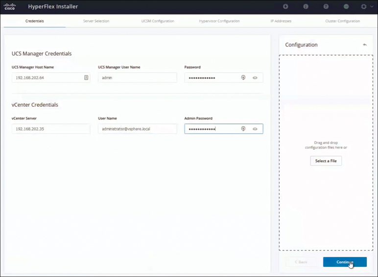
Figure 3-18 Entering UCS Manager and vCenter Credentials
On the Server Selection page, the UCS Manager credentials you provided are used to discover the UCSM configuration and list the already discovered HyperFlex servers, as shown in Figure 3-19.
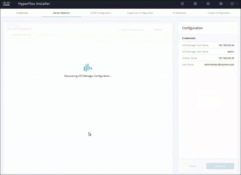
Figure 3-19 Discovering HyperFlex Servers: UCSM
There is also an option to configure server ports on UCS Manager from the installer. Select the unassociated servers that will be used for the HyperFlex installation. The example in Figure 3-20 shows three servers selected to deploy a three-node HyperFlex cluster. Click Continue on the Server Selection page to continue the UCSM configuration.
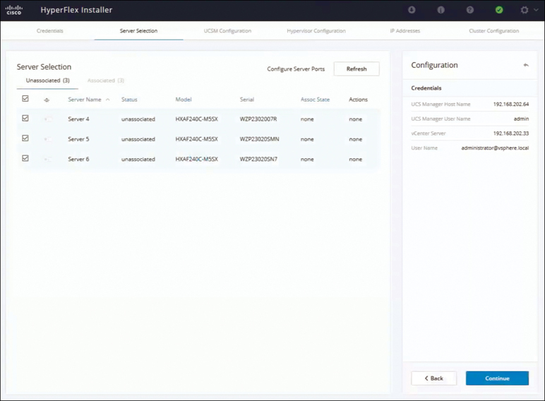
Figure 3-20 Selecting Servers to Deploy as a Three-Node HyperFlex Cluster
On the UCSM Configuration page, configure VLAN, MAC pool, and Cisco IMC access (out-of-band or in-band CIMC access), as shown in Figure 3-21.
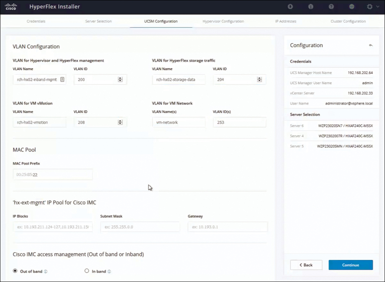
Figure 3-21 UCSM Configuration Details
Note
Use separate subnets and VLANs for each of the networks. Select a prefix that is not used with any other MAC address pool across all UCS domains.
If you want to add external storage, configure iSCSI storage and FC storage details toward the bottom of the UCSM Configuration. In the Advanced section at the bottom of this page, configure the UCS server firmware version, HyperFlex cluster name, and organization name, as shown in Figure 3-22:
HyperFlex cluster name: The HyperFlex cluster name is applied to a group of HX servers in a given cluster. The HyperFlex cluster name adds a label to service profiles for easier identification.
Organization name: Specify a unique org name to ensure isolation of the HyperFlex environment from the rest of the UCS domain. Click Continue to apply the UCSM Configuration settings.

Figure 3-22 UCSM Configuration Advanced Section
On the Hypervisor Configuration page (see Figure 3-23), configure the subnet mark, gateway, and IP address for the hypervisor settings and hypervisor credentials. In the Hypervisor Settings section, select Make IP Addresses and Hostnames Sequential to make the IP addresses sequential. Click Continue to configure the IP addresses.

Figure 3-23 Hypervisor Configuration
On the IP Addresses page, shown in Figure 3-24, configure the management and data IP addresses for hypervisor and storage controller. Select Make IP Addresses Sequential to make the IP addresses sequential. For each HX node, enter the hypervisor, storage controller, management, and data IP addresses. For the IP addresses, specify whether the network belongs to the data network or the management network.

Figure 3-24 Configuring IP Addresses
Also configure the cluster IP address for management and data. If a node with a cluster IP address becomes unavailable, the cluster IP address is moved to another node in the storage cluster. Click Continue to apply the IP Addresses page settings.
Note
Compute-only nodes can be added only after a storage cluster is created.
On the Cluster Configuration page, shown in Figure 3-25, for the Cisco HX storage cluster, complete the following fields to begin deploying the HyperFlex cluster:
In the Replication Factor drop-down menu, specify the number of redundant replicas of your data across the storage cluster. Set the replication factor to either 2 or 3 redundant replicas:
For hybrid servers (servers that contain SSD and HDDs), the default value is 3.
For all flash servers (servers that contain only SSDs), select either 2 or 3.
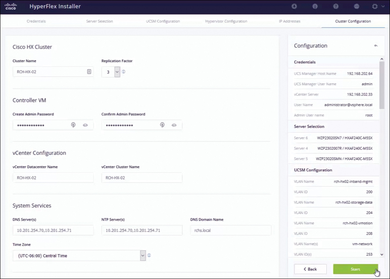
Figure 3-25 Cisco HX Storage Cluster Configuration
A replication factor of 3 is highly recommended for all environments except Hyper- Flex Edge. A replication factor of 2 has a lower level of availability and resiliency. The risk of outage due to component or node failures should be mitigated by having active and regular backups.
In the Controller VM section, create a new password for the administrative user of the HyperFlex cluster. A default administrator username and password are applied to the controller VMs. The VMs are installed on all converged and compute-only nodes.
In the vCenter Configuration section, complete the following fields:
vCenter Datacenter Name: Enter the vCenter data center name for the Cisco HyperFlex cluster.
vCenter Cluster Name: Enter the vCenter cluster name.
In the System Services section, configure the DNS server, NTP server, DNS domain name, and time zone.
In the Connected Services section of the Cluster Configuration page, shown in Figure 3-26, select Enable Connected Services to enable Auto-Support and Intersight management.
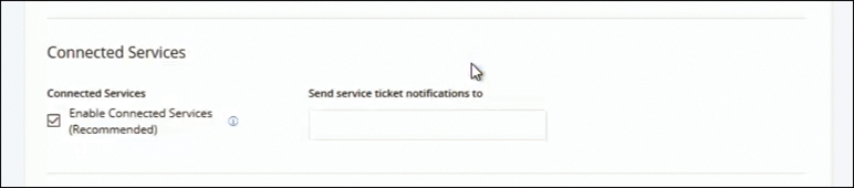
Figure 3-26 Enabling Connected Services
In Send service ticket notifications to, enter the email address for sending SR notifications when triggered by Auto-Support.
In the Advanced Configuration section of the Cluster Configuration page, shown in Figure 3-27, configure the following:
Jumbo Frames: By selecting Enable Jumbo Frames on Data Network, you can set the MTU size for the storage data network on the host vSwitch switches and vNICs, as well as each storage controller VM. The default value is 9000.
Disk Partitions: If you select Clean up disk partitions, you can remove all existing data and partitions from all nodes added to the storage cluster for manually prepared servers. Select this option to delete existing data and partitions. You must back up any data that should be retained.
(Optional) vCenter Single-Sign-On Server: This information is required only if the SSO URL is not reachable.
Virtual Desktop (VDI): Check this option for VDI-only environments.
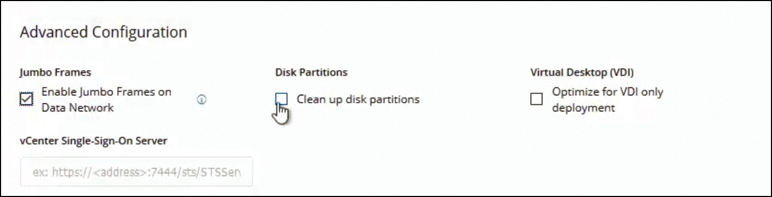
Figure 3-27 Cluster Configuration: Advanced Configuration
Click Start to begin deploying the HyperFlex cluster. The Progress page displays the progress of various configuration tasks, as shown in Figure 3-28.
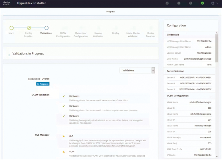
Figure 3-28 HyperFlex Installation ProgressÍ
Caution
Do not skip any validation warnings that appear during the installation process.
When the installation finishes, you see the Cluster Creation Successful message shown in Figure 3-29.
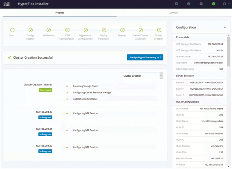
Figure 3-29 HyperFlex Installation Success
Browse to the Summary page, shown in Figure 3-30, to review the configuration information.
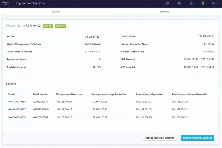
Figure 3-30 HyperFlex Installer Summary
HX Data Platform Installer Navigation Aid Buttons
On the HyperFlex installer, you have the following options:
Export Configuration: Click the down arrow icon to download a JSON configuration file.
Workflow Info: Hover over the information icon to view the current workflow. For HyperFlex cluster creation, the workflow info is Create Workflow = Esx.
Tech Support: Click the question mark icon to view details related to the HyperFlex Data Platform software version. Click Create New Bundle to create a tech support bundle for Cisco TAC.
Save Changes: Click the circle icon to save changes made to the HyperFlex cluster configuration parameters.
Settings: Click the gear icon to start over or log out.
Running the Postinstallation Script
To complete the postinstallation tasks, you can run a postinstallation script on the installer VM. It is important to run post_install to confirm network operation immediately following the deployment of the HyperFlex System. Follow these steps to do so:
Step 1. Use an SSH client to connect to the shell on the installer VM.
Step 2. Log in with installer VM root credentials.
Step 3. Type post_install and press Enter.
Step 4. Set the postinstallation script parameters as specified in Table 3-14.
Table 3-14 Postinstallation Script Parameter Settings
Setting |
Description |
Enable high availability/DRS on cluster |
Enable the vSphere high availability feature, according to best practice. |
Disable SSH warning |
Suppress the SSH and shell warnings in vCenter. |
Add vMotion interfaces |
Configure vMotion interfaces according to best practice. Requires IP address and VLAN ID input. |
Add VM network VLANs |
Add additional guest VLANs to Cisco UCS Manager and within ESXi on all cluster hosts. |
Note
If you run into any postinstallation script issues, set the postinstallation script parameters manually.
Sample Postinstallation Installation Script
You can log in to the installer VM and run the following post_install script to complete the installation steps explained above:
root@Hyperflex-Installer:~# post_install

Select post_install workflow-

 1. New/Existing Cluster
 2. Expanded Cluster (for non-edge clusters)
 3. Generate Certificate

Selection: 1
Logging in to controller hx-02-cmip.rchs.local
HX CVM admin password:
Getting ESX hosts from HX cluster...
vCenter URL: 192.168.202.35
Enter vCenter username (user@domain): [email protected]
vCenter Password:
Found datacenter RCH-HX-02
Found cluster RCH-HX-02

post_install to be run for the following hosts:
 hx-02-esxi-01.rchs.local
 hx-02-esxi-02.rchs.local
 hx-02-esxi-03.rchs.local

Enter ESX root password:

Enter vSphere license key?  (y/n) n

Enable HA/DRS on cluster? (y/n) y
Successfully completed configuring cluster HA.

Disable SSH warning? (y/n) y

Add vmotion interfaces? (y/n) y
 Netmask for vMotion: 255.255.254.0
 VLAN ID: (0-4096) 208
 vMotion MTU is set to use jumbo frames (9000 bytes). Do you want to
   change to 1500 bytes? (y/n) y
 vMotion IP for hx-02-esxi-01.rchs.local: 192.168.208.17
 Adding vmotion-208 to hx-02-esxi-01.rchs.local
 Adding vmkernel to hx-02-esxi-01.rchs.local
 vMotion IP for hx-02-esxi-02.rchs.local: 192.168.208.18
 Adding vmotion-208 to hx-02-esxi-02.rchs.local
 Adding vmkernel to hx-02-esxi-02.rchs.local
 vMotion IP for hx-02-esxi-03.rchs.local: 192.168.208.19
 Adding vmotion-208 to hx-02-esxi-03.rchs.local
 Adding vmkernel to hx-02-esxi-03.rchs.local

Add VM network VLANs? (y/n) n

Run health check? (y/n) y

Validating cluster health and configuration...

Cluster Summary:
     Version – 3.5(2e)
     Model - HXAF240C-M5SX
     Health - HEALTHY
     ASUP enabled - Trues

root@Hyperflex-Installer:~#
Refer to the sample script, where post_install script is run to generate certificate.
root@Cisco-HX-Data-Platform-Installer:~# post_install
Select post_install workflow-

 1. New/Existing Cluster
 2. Expanded Cluster
 3. Generate Certificate

 Selection: 3
 Certificate generation workflow selected

Logging in to controller 192.168.200.23
HX CVM admin password:
Getting ESX hosts from HX cluster...

Select Certificate Generation Workflow-

 1. With vCenter
 2. Without vCenter

 Selection: 1
vCenter URL: 192.168.202.33
Enter vCenter username (user@domain): [email protected]
vCenter Password:
Starting certificate generation and re-registration.
Trying to retrieve vCenterDatacenter information ....
Trying to retrieve vCenterCluster information ....
Certificate generated successfully.
Cluster re-registration in progress ....
Cluster re-registered successfully.

root@HyperFlex-Installer:~#
Note
Workflow 3 is mandatory to have a unique SSL certificate in the cluster. When you generate this certificate, it replaces your current certificate. If you’re performing cluster expansion, this option is not required.
Upon successful completion of the post_install script, the summary of the configuration executed based on the chosen option is displayed under Cluster Summary.
Installing HyperFlex Edge/Robo Cluster (ESXi, 3 Node)
Cisco HyperFlex Edge brings the simplicity of hyperconvergence to ROBO and edge environments. The following sections describe the deployment of HyperFlex Edge.
Table 3-15 provides a supportability summary for HyperFlex Edge clusters.
Table 3-15 Supportability Summary for Edge Clusters
Limitation |
Support |
Cluster type |
HX220c M4 Hybrid cluster HX220c M5 Hybrid cluster HXAF220c M4 All Flash cluster HXAF220c M5 All Flash cluster |
Cluster size |
Two, three, or four nodes; cluster expansion workflow is not supported in HyperFlex Edge configuration |
Replication factor |
Two |
Networking |
1 GB or 10 GB networking without Cisco UCS fabric interconnects; HX Edge systems do no implement QoS |
HX clusters per vCenter |
Up to 100 |
HyperFlex Edge Deployment Options
HyperFlex Edge can be deployed using Cisco Intersight from the cloud or by using the on-premises installer, depending on the requirements:
HyperFlex on-premises OVA installer: Use this option for on-premises Edge deployments for three- and four-node clusters. This type of deployment supports all three network topologies and requires download and installation of the installer along with local network access. Note that use of the on-premises installer is not support for two-node HyperFlex Edge clusters.
Intersight installer: Use this option to deploy HyperFlex Edge from the cloud. This deployment option supports all Edge cluster sizes and network topologies. See Chapter 7 for more details on this option.
HyperFlex On-Premises OVA Installer
Cisco HyperFlex Edge supports three networking topologies:
Single Gigabit Ethernet switch
Dual Gigabit Ethernet switches
10 Gigabit Ethernet switch (either single or dual)
The choices of configuration depend on requirements and the available switching hardware. The topology section in Chapter 2 describes specific requirements for each topology, as well as common network requirements that apply to all three topologies.
The rest of the pre-installation requirements (for example, IP address, port requirements, vCenter requirements) are similar to those for the HyperFlex standard cluster installation. Please see the section “Configuring and Deploying a Standard HyperFlex Cluster,” earlier in this chapter, for more details.
Installation Overview
Table 3-16 summarizes the installation workflow for Edge deployments. As you can see, steps 1–3 are the same for Gigabit Ethernet and 10 Gigabit Ethernet deployments. However, step 4 is applicable to Gigabit Ethernet deployments, and steps 5–6 are for 10 Gigabit Ethernet deployments.
Table 3-16 HyperFlex Edge Installation Steps
Step |
Description |
Reference |
Applicability |
1 |
Complete the preinstallation checklist. |
Make one of the following selections, based on your switch configuration:
|
Gigabit Ethernet and 10 Gigabit Ethernet |
2 |
Complete the installation prerequisites. |
Rack Cisco HyperFlex Nodes Configure Networking for Cisco Integrated Management Controller (CIMC) Verifying Firmware Versions |
Gigabit Ethernet and 10 Gigabit Ethernet |
3 |
Download and deploy the Cisco HX Data Platform installer. |
Deploying the Cisco HX Data Platform Installer |
Gigabit Ethernet and 10 Gigabit Ethernet |
4 |
Deploy the Cisco HyperFlex Edge cluster. |
Complete the following steps to configure your edge cluster and verify successful installation:
|
Gigabit Ethernet only |
5 |
SSH to the installer VM and run a script to complete specific configuration tasks. |
(10 Gigabit Ethernet Only) Run the Configuration Script |
10 Gigabit Ethernet only |
6 |
Deploy Cisco HyperFlex Edge cluster. |
(10 Gigabit Ethernet Only) Configuring a HyperFlex Cluster |
10 Gigabit Ethernet only |
Configuring and Deploying a HyperFlex Edge Cluster (Gigabit Ethernet Only)
After completing the preinstallation checklist, in a web browser, enter the IP address of the installer VM and click Accept or Continue to bypass any SSL certificate errors.
Note
A two-node edge cluster can be deployed only from Intersight. See Chapter 7 for more details.
Log in to the Cisco HX Data Platform installer using the username root and the password provided as part of the OVA deployment. Read the end-user license agreement, check I accept the terms and conditions, and click Login.
On the Select a Workflow page, click Create Cluster > Edge Cluster, as shown in Figure 3-31.

Figure 3-31 Selecting a Workflow
On the Credentials page, complete the fields shown in Figure 3-32 and click Continue.
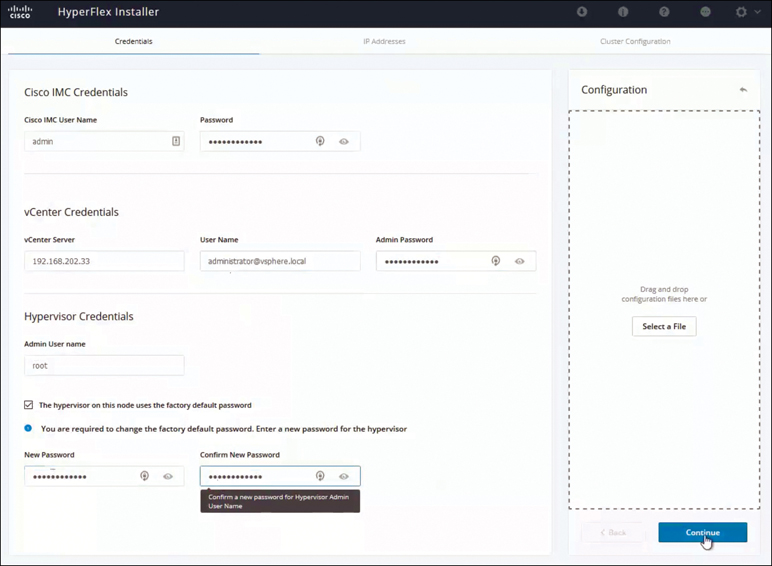
Figure 3-32 Configuring Credentials
On the IP Addresses page, enter the assigned address for each server, as shown in Figure 3-33, and click Continue.
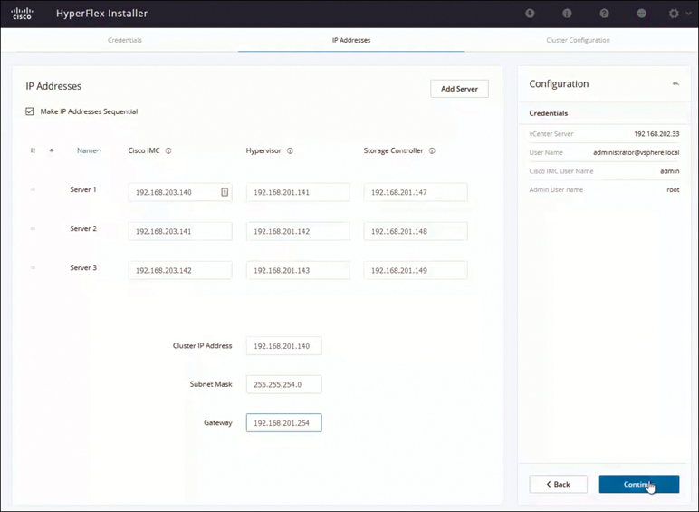
Figure 3-33 Configuring IP Addresses
On the Cluster Configuration page, complete the fields as shown in Figure 3-34 and click Start.

Figure 3-34 Cluster Configuration
In the Connected Services section of the Cluster Configuration page (see Figure 3-35), select Enable Connected Services to enable Auto-Support and Intersight management. In the Send service ticket notifications to box, enter the email address for sending SR notifications when triggered by Auto-Support.
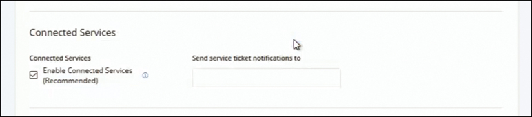
Figure 3-35 Connected Services
In the Advanced Configuration section of the Cluster Configuration page, shown in Figure 3-36, configure the following:
Jumbo frames: By selecting Enable Jumbo Frames on Data Network, you can set the MTU size for the storage data network on the host vSwitch switches and vNICs, as well as each storage controller VM. The default value is 9000.
Disk Partitions: If you select Clean up disk partitions, you can remove all existing data and partitions from all nodes added to the storage cluster for manually prepared servers. Select this option to delete existing data and partitions. You must back up any data that should be retained.
(Optional) vCenter Single-Sign-On Server: This information is required only if the SSO URL is not reachable.
Virtual Desktop (VDI): Check this option for VDI-only environments.
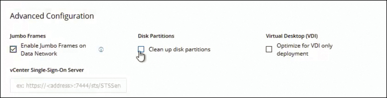
Figure 3-36 Advanced Configuration
When you click Start, the installation process starts, as shown in Figure 3-37.
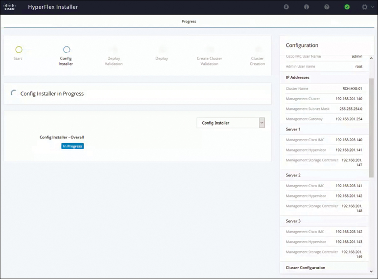
Figure 3-37 Installation Progress
When the installation is complete (see Figure 3-38), the installer takes you to the summary page (see Figure 3-39), on which you can Launch HyperFlex Connect to view the cluster information.

Figure 3-38 Successful Cluster Creation
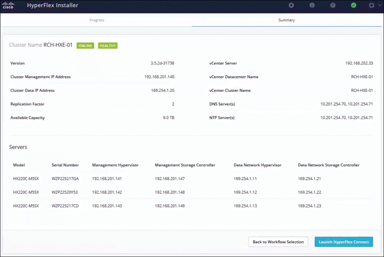
Figure 3-39 HyperFlex Cluster Installation Summary
Configuring and Deploying a HyperFlex Edge Cluster (10 Gigabit Ethernet Only)
To deploy a 10 Gigabit Ethernet HyperFlex edge cluster, you need to perform an additional step of running the configuration script (hx_edge) along with all the same steps for deploying HyperFlex Edge (Gigabit Ethernet).
Follow these steps:
Note
For Gigabit Ethernet installation, you do not have to run the configuration script
Step 1. SSH to the installer VM.
Step 2. Run the ~#hx_edge command to start the configuration script.
Step 3. Enter y to continue in interactive mode.
Step 4. Follow the onscreen prompts to complete the installation.
Step 5. When all the inputs have been entered and confirmed, enter y to begin the first phase of the 10 Gigabit Ethernet HX Edge deployment.
Step 6. The configuration task may take several minutes to complete. Check the summary view to view the completion status of each of the various tasks.
Figure 3-40 shows the results from a sample script run.

Figure 3-40 10 Gigabit Ethernet HyperFlex Edge Cluster hx_edge Script
After you run the script and complete the steps, deploy the installer and run the installation tasks as described in the section “Configuring and Deploying a HyperFlex Edge Cluster (Gigabit Ethernet Only),” earlier in this chapter.
HyperFlex Edge Postinstallation Tasks
To run the postinstallation script (which is the same for both HX Edge Gigabit Ethernet and HX Edge 10 Gigabit Ethernet), do the following:
Step 1. In a web browser, navigate to http://<installer VM IP address>/mssh and log in using the username root and your password.
Step 2. Run ~#post_install.py to start the postinstallation tasks in the web-based SSH window.
On execution of the post installation script, the following options appear:
Select post_install workflow-

1. New/Existing Cluster
2. Expanded Cluster
3. Generate Certificate
Note
Workflow 3 is mandatory to have a unique SSL certificate in the cluster. When you generate this certificate, it replaces your current certificate. If you’re performing cluster expansion, this option is not required.
Choose one of the following options as per the requirement:
1: Choose this option to run the postinstallation script on a newly created cluster or on an existing cluster. When you select this option, the script runs the postinstallation operations on all the nodes in the cluster.
2: Choose this option to run the postinstallation script on expanded nodes or on newly added nodes after executing the expansion workflow. When you select this option, the script fetches the list of expanded nodes and runs the postinstallation operations on the expanded nodes.
3: Choose this option to have a unique SSL certificate in the cluster. When you select this option, the current certificate is replaced with the newly created SSL certificate. This option is not required for the cluster expansion.
Step 3. Follow the onscreen prompts to complete the installation.
The post_install script completes the following:
Licenses the vCenter host.
Enables high availability/DRS on the cluster per best practices.
Suppresses SSH/shell warnings in vCenter.
Configures vMotion according to best practices.
Adds additional guest VLANs/port groups.
Performs a HyperFlex Edge configuration check.
On successful completion of the post_install workflow, the summary of the configuration executed based on the chosen option is displayed under Cluster Summary.
Installing a HyperFlex Stretch Cluster (ESXi)
A HyperFlex stretch cluster enables you to deploy an active/active disaster-avoidance solution for mission-critical workloads requiring high uptime (a near-zero recovery time objective) and no data loss (a zero recovery point objective). As illustrated in Figure 3-41, a stretch cluster is a single cluster with geographically distributed nodes. Both sides of the cluster act as primary for certain user VMs. The data for these VMs is replicated synchronously on the other site. Stretch clusters enable you to access an entire cluster even if one of the sites completely goes down. Typically, these sites are connected with a low-latency dedicated high-speed link between them.
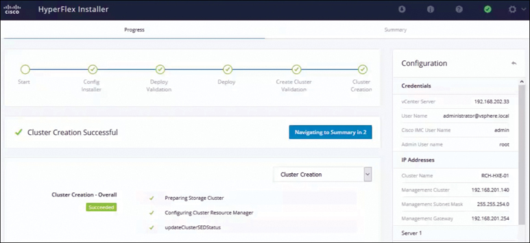
Figure 3-41 Stretch Cluster Topology
Preinstallation Checklist
This section covers prerequisites for successfully deploying a HyperFlex stretch cluster. It describes the guidelines to follow when deploying a stretch cluster.
Network Requirements and Network Topology
Before you deploy a stretch cluster, ensure that you meet the following requirements:
10 Gbps dedicated, 5 ms round-trip time (RTT) latency between the two active sites is required.
100 Mbps, 200 ms RTT worst-case latency for 16 KB packets between the active sites and witness site is required.
Existing fabric interconnects are supported, provided that the fabric interconnects support M5 servers.
User VMs should be capable of vMotion to any site, without impacting external network connectivity to these VMs.
As with regular HX clusters, two separate IP subnets are required, both of them over stretch L2: one subnet for data traffic and one for management traffic, with the management subnet reachable from vCenter and the witness node.
The static IP address assigned to the witness VM can be changed only with cluster redeployment. If a DHCP server is used to define the network configuration, the IP address needs to be dedicated to the witness VM.
Figure 3-42 illustrates the stretch cluster network topology.
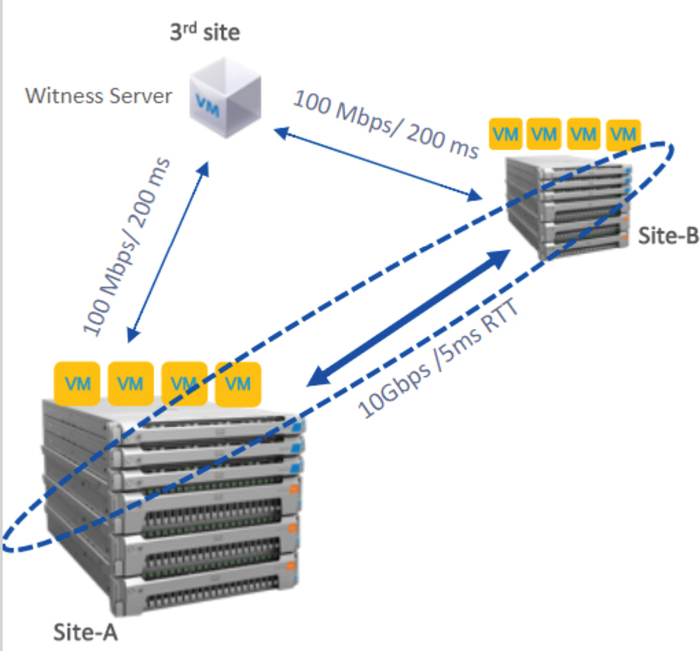
Figure 3-42 Stretch Cluster Network Topology
Witness Requirements
Consider the following guidelines when deploying a Witness VM for a HyperFlex Stretched Cluster:
Configure and enable NTP on all servers.
An independent third witness site is required.
Both of the main sites must have connectivity to the third witness site, with a minimum bandwidth of 100 Mbps and 200 ms RTT worst-case latency for 16 KB packets.
Site must have the capability to deploy and run an Open Virtualization Format (OVF) image.
Network Latency Requirements for the Witness VM
Consider the following network latency requirement guidelines when creating a HyperFlex Stretched Cluster:
The HyperFlex stretch cluster solution requires that the witness VM be located in a third site to ensure that a storage site failure does not affect the witness VM.
The solution can support a witness VM bandwidth as low as 100 Mbps and 200 ms RTT worst-case latency for 16 KB packets.
Latency to the witness VM impacts site failure times, and it is recommended, for larger clusters with significant load and data, to have RTT times in the order of 10 ms or lower.
Fabric Interconnect and Node Requirements
Hyperflex Stretch cluster requires redundant Fabric interconnect and Hyperflex Nodes on each site. Consider the following requirements for Fabric Interconnect and Nodes:
Symmetric configuration is required across both sites.
There must be a minimum of two converged nodes on each site.
A maximum of 16 converged nodes on each site is supported. Ensure that both sites have the same number of converged nodes.
Converged nodes have to be M5 nodes.
Ensure that both parts of the fabric interconnect pair are of the same model in the same domain.
Compute-only nodes are supported.
VMware Requirements
VMware Enterprise Plus edition with a HyperFlex stretch cluster is highly recommended to ensure proper failover behavior and guarantee high performance during normal operations. While it is possible to run a stretch cluster without VMware Enterprise Plus edition, the advanced DRS features such as site affinity will not be available, negating some of the intended operational functions of a stretch cluster. Consider the following requirements for vCenter configuration:
Use a single vCenter for both sites.
The vCenter can be a VM running at the same site as the witness.
Nested vCenter is not supported in a stretch cluster.
vCenter must be configured independently for high availability, as required.
ACI Requirements
The supported ACI configurations are as follows:
1 POD and 2 POD (in a multi-POD configuration)
ESXi version 6.5u3
HyperFlex versions 3.5(2f), 3.5(2g), and later
ACI version 4.1(1k)
UCS Manager Requirements
Two separate, manually synchronized fabric interconnect domains are required.
VLAN Requirements
Consider the following VLAN requirements when deploying a HyperFlex Stretched Cluster:
IP addresses for nodes on both sites are required.
Stretch VLANs across both sites are required.
Stretch Witness
A HyperFlex witness node is mandatory in a stretch cluster environment to achieve quorum in case of total failure in any of the sites or when the network link between the sites encounters a failure.
In case of accidental deletion or loss of the witness VM, you can replace the witness VM by contacting Cisco TAC. The witness VM requires a static IP address that cannot be changed without cluster redeployment. If a DHCP server is used to define the network configuration, the IP address needs to be dedicated to the witness VM. Table 3-17 outlines the stretch cluster witness VM network requirements.
Table 3-17 Witness VM Network Requirement
Port Number |
Service/Protocol |
Source |
Port Destinations |
Essential Information |
2181 2888 3888 |
Zookeeper/TCP |
Witness |
Each CVM node |
Bidirectional management addresses |
8180 |
Exhibitor (Zookeeper lifecycle)/TCP |
Witness |
Each CVM node |
Bidirectional management addresses |
80 |
HTTP/TCP |
Witness |
Each CVM node |
Potential future requirement |
433 |
HTTP/TCP |
Witness |
Each CVM node |
Potential future requirement |
Deploying the Witness Node
A witness VM must be deployed on an ESXi server that has sufficient hosting capability. The witness VM requires four vCPUs, 8 GB of memory, and 40 GB of disk space. Ensure that the virtual network on this ESXi host is reachable from both of the stretch cluster sites.
Download the HyperFlex witness node onto your desktop or host that runs vSphere Web Client from cisco.com (for example, HyperFlex-Witness-1.0.2.ova). HyperFlex witness node version 1.0.2 is supported in HX Data Platform 3.5(1a) and later. Follow these steps:
Step 1. Log in to vSphere Web Client. Choose the ESXi server where the witness should be deployed. Right-click the ESXi host and select Deploy OVF Template.
Step 2. Browse and select the HyperFlex-Witness.ova file, as shown in Figure 3-43. Click Next.
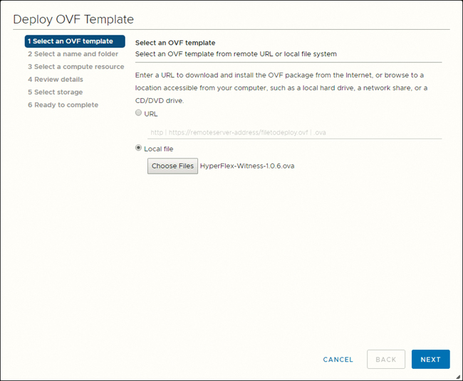
Figure 3-43 Deploying a Witness VM OVA
Step 3. Specify a unique name for the witness node in the Virtual Machine Name field. Select a location for the virtual machine from the drop-down list. Click Next.
Step 4. From the Select a compute resource drop-down list, choose the ESXi host where you want to deploy the witness node. Click Next.
Step 5. In the Review details pane, as shown in Figure 3-44, verify the template details and then click Next.
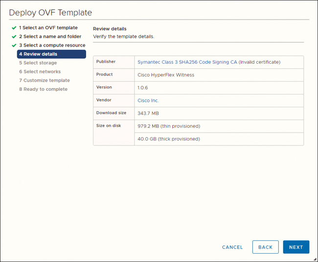
Figure 3-44 Reviewing Details
Step 6. In the Select Storage pane, select the datastore where the virtual machine will reside (and ensure that this datastore has at least 40 GB of available free space). Click Next.
Step 7. In the Select Networks pane, select a destination network port group to which the witness VM must connect. Click Next.
Step 8. On the Customize Template page, complete the fields that are relevant for your configuration (for example, IP address, netmask, default gateway, DNS, NTP). Click Next.
Step 9. On the Ready to complete page (see Figure 3-45), verify all the details entered. Click Finish.

Figure 3-45 Customizing the Template and Deploying the OVA
HyperFlex Stretch Cluster Network IP Addressing
IP addresses for a HyperFlex stretch cluster need to be allocated from the appropriate subnets and VLANs.
Ensure that the data and management networks are on different subnets for a successful installation. In addition, ensure that the IP addressing is in the same subnet for the same components (for example, management network IP addresses, data network IP addresses).
Table 3-18 lists the IP address requirements for deploying a HyperFlex stretch cluster. Tables 3-19 and 3-20 provide examples of stretch cluster IP addressing for two sites.
Table 3-18 Example: Stretch Cluster IP Addressing
Storage cluster management IP address |
10.10.10.128 |
Storage cluster data IP address |
192.168.10.160 |
Subnet mask IP address |
255.255.255.0 |
Subnet mask IP address |
255.255.255.0 |
Default gateway IP address |
10.10.10.1 |
Default gateway IP address |
192.168.10.1 |
Table 3-19 Example: Stretch Cluster IP Addressing for Site A
Management Network IP Addresses (Must Be Routable) |
Data Network IP Addresses (Does Not Have to Be Routable) |
|||
ESXi Hostname* |
Hypervisor Management Network |
Storage Controller Management Network |
Hypervisor Data Network (Not Required for Cisco Intersight) |
Storage Controller Data Network (Not Required for Cisco Intersight) |
Server 1 |
10.10.10.2 |
10.10.10.32 |
192.168.10.2 |
192.168.10.32 |
Server 2 |
10.10.10.3 |
10.10.10.33 |
192.168.10.3 |
192.168.10.33 |
Server 3 |
10.10.10.4 |
10.10.10.34 |
192.168.10.4 |
192.168.10.3 |
Server 4 |
10.10.10.5 |
10.10.10.35 |
192.168.10.5 |
192.168.10.35 |
Server 5 |
10.10.10.6 |
10.10.10.36 |
192.168.10.6 |
192.168.10.36 |
Table 3-20 Example: Stretch Cluster IP Addressing for Site B
Management Network IP Addresses (Must Be Routable) |
Data Network IP Addresses (Does Not Have to Be Routable) |
|||
ESXi Hostname* |
Hypervisor Management Network |
Storage Controller Management Network |
Hypervisor Data Network (Not Required for Cisco Intersight) |
Storage Controller Data Network (Not Required for Cisco Intersight) |
Server 1 |
10.10.10.64 |
10.10.10.96 |
192.168.10.64 |
192.168.10.96 |
Server 2 |
10.10.10.65 |
10.10.10.97 |
192.168.10.65 |
192.168.10.97 |
Server 3 |
10.10.10.66 |
10.10.10.98 |
192.168.10.66 |
192.168.10.98 |
Server 4 |
10.10.10.67 |
10.10.10.99 |
192.168.10.67 |
192.168.10.99 |
Server 5 |
10.10.10.68 |
10.10.10.100 |
192.168.10.68 |
192.168.10.100 |
HyperFlex Stretch Cluster Guidelines
Consider the following guidelines when creating a HyperFlex stretch cluster:
HX Data Platform Enterprise Edition licensing is required to use a HyperFlex stretch cluster.
vSphere Enterprise Plus licensing is required for full-featured HyperFlex stretch cluster functionalities such as VM load balancing and VM migration.
Ensure that DRS is enabled.
Support the stretch cluster scale:
There must be a minimum of two nodes on each site. The minimum overall cluster size across both sites is 4.
For a small form factor (SFF), the maximum cluster size across both sites is 64. The maximum converged node count is 16 per site. The compute-to- converged node ratio can be 2:1, and the maximum limit of nodes per site must not exceed 32. For example, you can have 11 converged and 21 compute nodes per site.
For a large form factor (LFF), the maximum cluster size is 48. The maximum converged node count is 8 per site. The compute-to-converged node ratio can be 2:1, and the maximum limit of nodes per site must not exceed 24. For example, you can have 8 converged and 16 compute nodes per site.
There must be a redundant fabric interconnect configuration on each site.
There must be symmetric cluster configuration across both sites. The number of nodes and the model of HX nodes should be the same on both sites.
VMs are placed correctly within site affinity only if VMware high availability and DRS are enabled before VM creation. Otherwise, the correct placement of VM for proper affinity is not guaranteed.
HyperFlex Native Replication is supported between stretch clusters and between stretch clusters and standard clusters.
It is a best practice to have two datastores—one per site—with the appropriate affinity.
HyperFlex Stretch Cluster Limitations
Consider the following limitations when creating a HyperFlex stretch cluster:
Self-encrypting drives (SEDs) are not supported. However, VM-based third-party software encryption is supported.
Overlay networking and L3 protocols are not supported. L2 adjacency is required for the data and management networks.
Auto failback of VMs after site failure is not supported. You must manually migrate the failover VMs to the site.
A stretch cluster is not supported on Hyper-V platform.
Online rolling upgrades are supported only for the HX Data Platform. Cisco UCS Manager upgrades and VMware ESXi upgrades must be performed manually on one node at a time or performed offline.
Upgrading from a standalone cluster to a stretch cluster configuration is not supported.
Stretch clusters are supported only on M5 nodes. Mixed M4/M5 clusters are not supported.
NVMe converged nodes are not supported.
Hardware Acceleration Engine (HX-PCIE-OFFLOAD-1) is not supported.
A shared witness VM is not supported for stretch cluster deployments.
HyperFlex Stretch Cluster Installation
This section summarizes the steps that are involved in creating a stretch cluster using the HX Data Platform installer. All the configuration for a stretch cluster in this section will be done from a single HX installer. Figure 3-46 gives an overview of the workflow required to deploy a stretch cluster.
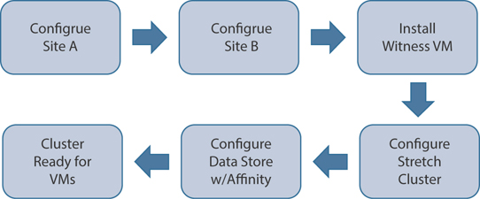
Figure 3-46 Stretch Cluster Deployment Workflow Overview
Figure 3-47 summarizes the installation workflow steps that are involved in creating a stretch cluster using the HX Data Platform installer.
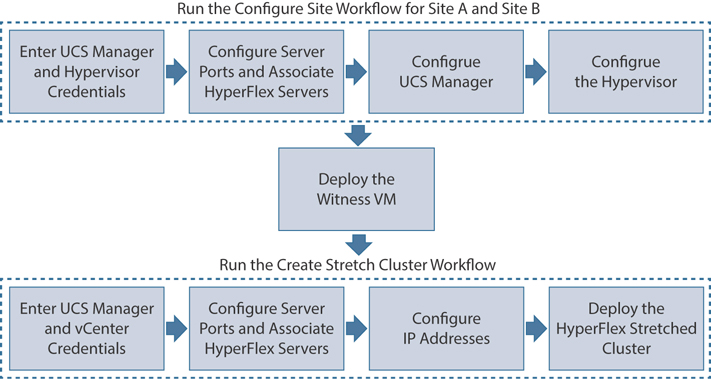
Figure 3-47 Stretch Cluster Deployment Workflow Using the HXDP Installer
Follow the workflow outlined in Table 3-21 during installation.
Table 3-21 Stretch Cluster Installation Workflow
Step |
Description |
Reference |
Create the stretch cluster sites: Run the configure site workflow for Site A and Site B. |
Log in to the HX Data Platform installer. Enter UCS Manager credentials and hypervisor credentials for both of the sites. |
Enter Credentials |
Configure the server ports and associate HyperFlex servers. |
Associate HyperFlex Servers |
|
Configure VLAN, MAC pool, hx-ext-mgmt IP pool for out-of-band CIMC, in-band CIMC, iSCSi storage, and FC storage. |
Configure UCS Manager |
|
Configure the hypervisor. |
Configure the Hypervisor |
|
Download and deploy the witness VM. |
Note that a witness VM is mandatory in a HyperFlex stretch cluster environment. |
Deploying the Witness Node |
Create your HyperFlex stretch cluster: Run the create stretch cluster workflow. |
Enter UCS Manager credentials for Site A and Site B, as well as vCenter credentials. |
Enter Credentials |
Configure the server ports and associate HyperFlex servers. |
Associate HyperFlex Servers |
|
Configure IP addresses. |
Configure IP Addresses |
|
Deploy the HyperFlex stretch cluster. |
Deploy a HyperFlex Stretch Cluster |
Follow these steps to install a stretch cluster:
Step 1. Log on to the HX installer to start the cluster configuration. If the installer is still showing the previous installation’s status, click on the sprocket in the bar above and select Start Over to begin a fresh install. On the Select a Workflow page, select Create Cluster > Stretch Cluster, as shown in Figure 3-48.
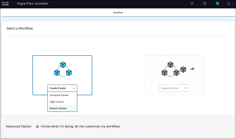
Figure 3-48 Selecting the Stretch Cluster Workflow
Step 2. Select Configure Site and enter the UCSM credentials and the site name (see Figure 3-49). Then click Continue.
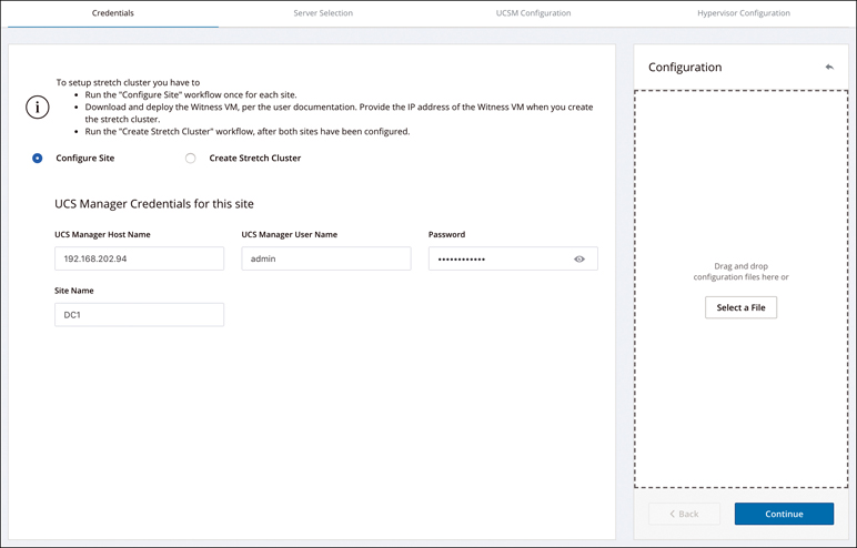
Figure 3-49 Configuring Site Credentials
Step 3. On the Server Selection page, as shown in Figure 3-50, select the source servers and click Continue. The Configuration pane on the right displays a detailed list of the credentials used. The Server Selection page also displays a list of unassociated HX servers under the Unassociated tab and a list of discovered servers under the Associated tab.
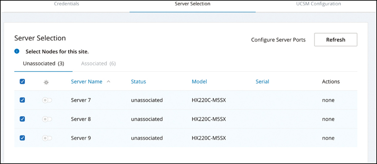
Figure 3-50 Server Selection
Step 4. On the UCSM Configuration page, enter the VLAN ID, VLAN names, MAC pool, IP pool for in-band of out-of-band, iSCSI storage, and FC storage (see Figure 3-51). Click Continue.
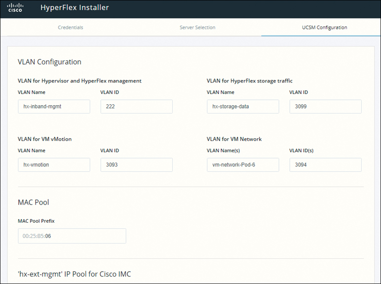
Figure 3-51 UCSM Configuration
Step 5. In the Hypervisor Settings section of the UCSM Configuration page, provide all the requested information (see Figure 3-52). Then click Configure Site to begin site configuration. The Progress page displays the progress of various configuration tasks.
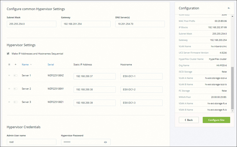
Figure 3-52 Hypervisor Configuration
Step 6. Confirm that the Site A hypervisor configuration is successful, as illustrated in Figure 3-53.
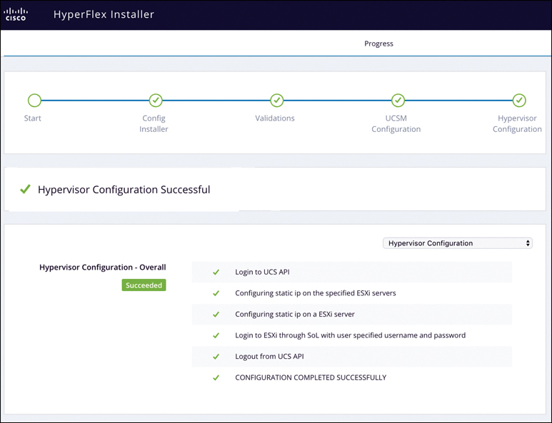
Figure 3-53 Configuration Success for Site A
Step 7. As illustrated in Figure 3-54, click on the sprocket and select Configure Site to begin the Site B configuration.
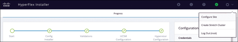
Figure 3-54 Configuring Site B
Step 8. Repeat steps 2 through 6 for Site B.
Step 9. Ensure that the witness VM has been deployed successfully. (Refer to the section “Deploying the Witness Node,” earlier in this chapter.)
Step 10. To begin configuring the stretch cluster, click the sprocket on the installer and select Create Stretch Cluster to begin the stretch cluster configuration.
Step 11. On the credentials screen (see Figure 3-55), provide the source (Site A) and target (Site B) UCSM, as well as credentials, site name, UCSM org name, and vCenter and hypervisor credentials. Click Continue to proceed to the Server Selection screen.
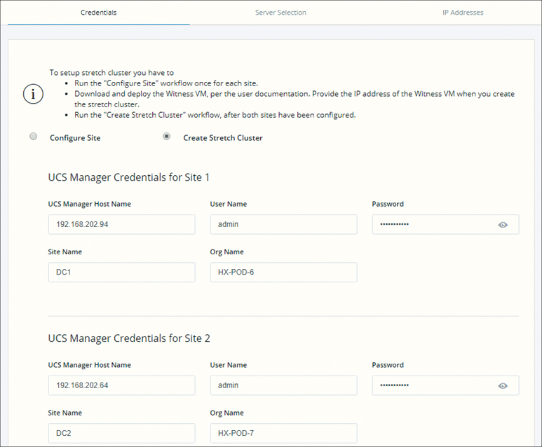
Figure 3-55 Configuring Credentials for a Stretch Cluster
Step 12. On the Server Selection page (see Figure 3-56), configure the server ports and associated HyperFlex servers. Servers from both sites Site A and Site B (named DC1 and DC2) are shown under Associated Servers.
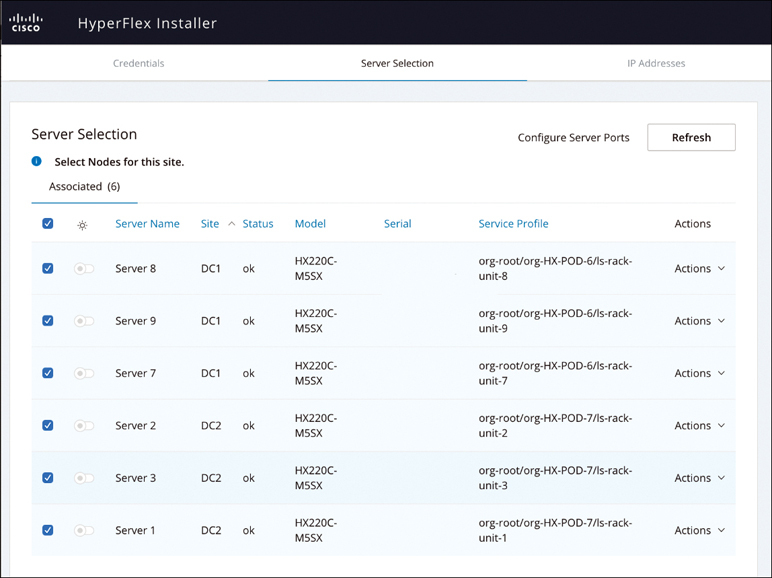
Figure 3-56 Server Selection: Site A and Site B
Step 13. On the IP Addresses page (see Figure 3-57), configure the IP addresses to be applied to the storage cluster. For each HX node, enter the hypervisor and storage controller IP addresses. For the IP addresses, specify the IP address belonging to the data network, the management network, the cluster IP address for the management and data networks, the subnet mask, and the IP address of the witness VM installed earlier. Click Continue.

Figure 3-57 Configuring IP Address Information
Step 14. On the Cluster Configuration page (see Figure 3-58), configure and deploy the HyperFlex stretch cluster. On this page, you can’t change the Replication Factor setting. For a stretch cluster, it’s 2+2.

Figure 3-58 Cluster Configuration
Step 15. In the Connected Services section of the Cluster Configuration page (see Figure 3-59), select Enable Connected Services to enable Auto-Support and Intersight management. In Send service ticket notifications to, enter the email address for sending SR notifications when triggered by Auto-Support.

Figure 3-59 Connected Services
Step 16. In the Advanced Networking section of the Cluster Configuration page (see Figure 3-60), complete the management and data VLAN tag for Site A and Site B and enter the management and data vSwitch names.
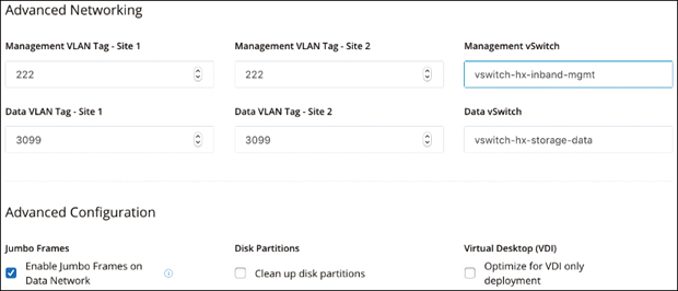
Figure 3-60 Advanced Configurations
Step 17. In the Advanced Configuration section of the Cluster Configuration page (refer to Figure 3-60), configure the following:
Jumbo frames: By selecting Enable Jumbo Frames on Data Network, you can set the MTU size for the storage data network on the host vSwitch switches and vNICs, as well as each storage controller VM. The default value is 9000.
Disk Partitions: If you select Clean up disk partitions, you can remove all existing data and partitions from all nodes added to the storage cluster for manually prepared servers. Select this option to delete existing data and partitions. You must back up any data that should be retained.
(Optional) vCenter Single-Sign-On Server: This information is required only if the SSO URL is not reachable.
Virtual Desktop (VDI): Check this option for VDI-only environments.
Step 18. Click Start to begin deploying the stretch cluster. The Progress page displays the progress of the various configuration tasks, as shown in Figure 3-61. When the process is complete, the HyperFlex servers are installed and configured, and you see the message Cluster Creation Successful.
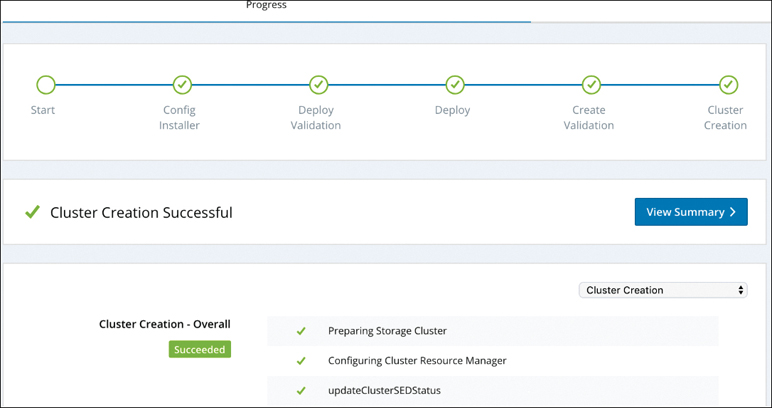
Figure 3-61 Stretch Cluster Creation Progress
HyperFlex Stretch Cluster Postinstallation
After the installation of a stretch cluster using the HX Data Platform installer, run the postinstallation script to finalize the configuration and set up the vMotion network. You can also run this script at a future time if needed.
If you wish to run the post_install.py script later, you can run the script directly from any control VM (CVM) by using the following procedure:
Step 1. Log in to a cluster IP (CIP) through a SSH server.
Step 2. Run the post_install script, which is available at /usr/share/springpath/ storfs-misc/hx-scripts/post_install.py.
Step 3. Follow the prompts and enter the required information.
Summary
This chapter covers all types of installations for HyperFlex clusters, including the following:
HyperFlex installation prerequisites
HyperFlex standard cluster deployment
HyperFlex edge cluster deployment
HyperFlex stretch cluster deployment
Postinstallation tasks
This chapter covers all the deployment steps using the on HyperFlex Data Platform on-premises installer. HyperFlex deployment from Intersight is covered in Chapter 7.
Chapter 4, “Managing HyperFlex,” discusses HyperFlex Connect and how it simplifies Day 2 operations.