

Graphical user interface overview
This chapter provides an overview of the graphical user interface (GUI) of IBM Spectrum Virtualize on the IBM Storwize V5000 Gen2 and shows you how to use the navigation tools.
Specifically, this chapter provides information about the following topics:
•Dashboard
3.1 Overview of IBM Spectrum Virtualize management software
A GUI can simplify storage management and provide a fast and more efficient management tool. IBM Spectrum Virtualize V8.1 GUI has significant changes from previous versions, such as the icons, color palette, object locations, and more. However, usability is a priority, as in all IBM Spectrum products, and usability is maintained in the GUI.
|
JavaScript: You must enable JavaScript in your browser. For Mozilla Firefox, JavaScript is enabled by default and requires no additional configuration. For more information about configuring your web browser, go to this website:
|
3.1.1 Access to the storage management software
To access the Storwize V5000 Gen2, complete the following steps:
1. To log on to the management software, type the IP address that was set during the initial setup process into the address line of your web browser. You can connect from any workstation that can communicate with the system. The login window opens (Figure 3-1).

Figure 3-1 Login window
We suggest that each user who operates IBM Spectrum Virtualize has an account that is not shared with someone else. The default user accounts need to be unavailable for remote access, or the passwords need to be changed from the default password and known only to the system owner or kept secured for emergency purposes only.
This approach helps to identify the personnel who are working on the device and to track all of the important changes in the systems. The Superuser account must be used for initial configuration only.
2. After a successful login, the IBM Spectrum Virtualize System pane displays the Dashboard with all relevant details of your system. Shown in Figure 3-2.

Figure 3-2 A first view
The IBM Spectrum Virtualize System pane is an important user interface. Throughout this chapter, we refer to it as the IBM Spectrum Virtualize System pane or System pane. In the remaining chapters, we do not explain how to access it each time.
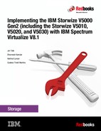
3.1.2 System pane layout
The System pane has four main sections for navigating through the management tool:
•Top
The top menu shows the navigation path so that the user knows the exact path.
The Actions option can be used at any time to add more enclosures, modify existing hardware, or rename the system.
The top menu also has a system overview (upper right corner) so that you can see global system topology.
•Left
The system menu (or set of function icons) is the main object that the users access. By using the system menu, the user can change or view any setting or parameter in the system.
•Center
Within the system view object, users can view or change parameters that mainly relate to the hardware of global system settings.
•Bottom
The informational pane consists of running tasks, capacity information, basic performance indicator, system health status, and status alerts.
Figure 3-3 shows these main areas.
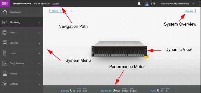
Figure 3-3 Main areas
The main areas are described:
•The left side of the window shows eight function icons. We refer to them collectively as a dynamic menu. The dynamic menu includes these function icons:
– Dashboard
– Monitoring menu
– Pools menu
– Volumes menu
– Hosts menu
– Copy Services menu
– Access menu
– Settings menu
Figure 3-4 shows the dynamic menu.

Figure 3-4 Dynamic menu
•The middle of the window shows a component model of the existing configuration. Hovering the mouse cursor over each component and its part highlights that part and provides a pop-up menu with a description that identifies important parameters and functions of this element. To see the rear of the component, you can dynamically rotate them as in a typical 360° view. Right-clicking a component or its part opens its menu showing actions, which are normally available from the dynamic menu on the left or from the Actions Button in the upper left corner.
Figure 3-5 shows the component model.

Figure 3-5 Component model
•The bottom of the window shows the performance indicator. It gives you information about how your machine is performing right now. This information covers only the external tasks for attached hosts. Figure 3-6 shows the performance indicator.
To see information about how the performance internally is, view the System statistic page, as shown in Figure 3-7 on page 84.
Figure 3-6 Performance indicator
Figure 3-7 shows the System statistic page.

Figure 3-7 System statistic page
•On the right upper area you get more information about the health of your system. The Event button shows the information shown in Figure 3-8.

Figure 3-8 Event button
Alternatively, you can use the Suggested tasks button shown in Figure 3-9.

Figure 3-9 Suggested Tasks
A help menu is shown in Figure 3-10.

Figure 3-10 Help Menu
Clicking any of these options provides more detailed information about the existing configuration, situation, or status of the IBM Spectrum Virtualize solution. Click any of these function icons to expand them and minimize them as required. In an error or warning situation, those indicators are extended by the status alerts icon in the upper-right corner, as shown in Figure 3-8 on page 84.
3.1.3 Navigation
Navigating in the management tool is simple. You can click with the cursor on one of the eight function icons and display a submenu of options. You can move the cursor to an option and select it. Figure 3-11 shows how to access, for example, the Pools option.

Figure 3-11 Navigate by using the menu options
3.1.4 Multiple selection
With the improved management tool, you can select multiple items by using the Shift and Ctrl keys. To select multiple items in a display, click the first item, press and hold the Shift key, and click the last item that you require in the list. All rows between those two items are selected and highlighted in light blue (Figure 3-12).

Figure 3-12 Multiple selections by using the Shift key
Similarly, if you want to select multiple items that are not in sequential order, click the first item, press and hold the Ctrl key, and click the other items that you need (Figure 3-13).

Figure 3-13 Multiple selections by using the Ctrl key
Another option for selecting volumes is selecting by mask. To select all volumes that have “V5000” in their name, click Filter, type V5000, and press Enter. All volumes with “V5000” in their name display. After you filter the volumes, you can easily select all of the displayed volumes or a subset by using the Ctrl key or Shift key technique that was explained previously (Figure 3-14).

Figure 3-14 Filtering volumes
3.1.5 Status indicators area
The status indicators area at the bottom of the System pane (Figure 3-15) shows a high-level status of the IBM Storwize V5000 storage system. Information shown there covers only the performance of the attached Host Systems.
Figure 3-15 Status indicators
Help
Another useful interface feature is the integrated help function. You can access help for certain fields and objects by moving the mouse cursor over the question mark (?) icon (Figure 3-16) next to the field. Panel-specific help is available by clicking Need Help or by using the Help link in the upper-right corner of the GUI.

Figure 3-16 Access to panel-specific help
3.2 Overview pane
The welcome pane of the GUI changed from the well-known former Overview pane to the new System pane, as shown in Figure 3-17. Clicking Overview in the upper-right corner of the System pane opens a modified Overview pane with functionality that is similar to previous versions of the software.

Figure 3-17 Opening the Overview pane
See 3.1.2, “System pane layout” on page 81 to understand the structure of the pane and how to navigate to various system components and manage them more efficiently and quickly.
3.3 Monitoring menu
Place the cursor over the Monitoring function icon to open the Monitoring menu (Figure 3-18 on page 90). The Monitoring menu offers the following navigation directions:
System From the System panel, you can view details about control and expansion enclosures and various hardware components of the system. The system uses base-2 (binary numeral) as capacity indicators for volumes, drives, and other system objects. The management GUI and the command-line interface (CLI) use different abbreviations to indicate capacity, but the value for these capacity indicators is the same. See 3.3.1, “System overview” on page 90.
Events The Events panel displays two types of events: messages and alerts. It also indicates the cause of any log entry. You can use this panel to filter messages that are related to events that occurred on the system. Some alerts have a four-digit error code and a fix procedure that helps you fix the problem.
Other alerts also require action but do not have a fix procedure. Messages are fixed when you acknowledge reading them and mark them as fixed. Each event has a time stamp that indicates when the action occurred or the command was submitted on the system.
When logs are displayed in the command-line interface, the time stamps for the logs in the CLI are the system time. However, when logs are displayed in the management GUI, the time stamps are translated to the local time where the web browser is running.
Performance Use real-time statistics to monitor CPU utilization, volume, interface, and MDisk bandwidth of your system and nodes. Each graph represents 5 minutes of collected statistics and provides a means of assessing the overall performance of your system. You can use system statistics to monitor the bandwidth of all the volumes, interfaces, and MDisks that are being used on your system.
You can also monitor the overall CPU utilization for the system. These statistics summarize the overall performance health of the system and can be used to monitor trends in bandwidth and CPU utilization. You can monitor changes to stable values or differences between related statistics, such as the latency between volumes and MDisks. These differences then can be further evaluated by performance diagnostic tools.
Additionally, with system-level statistics, you can quickly view bandwidth of volumes, interfaces, and MDisks. Each of these graphs displays the current bandwidth in megabytes per second (Mbps), and a view of bandwidth over time. Each data point can be accessed to determine its individual bandwidth use and to evaluate whether a specific data point might represent performance impacts.
For example, you can monitor the interfaces, such as for Fibre Channel or SAS interfaces, to determine whether the host data-transfer rate is different from the expected rate. You can also select node-level statistics, which can help you determine the performance impact of a specific node. As with system statistics, node statistics help you to evaluate whether the node is operating within normal performance metrics.
Background Tasks Use the Background Tasks page to view and manage current tasks that are running on the system. The Background Tasks page displays all long-running tasks that are currently in progress on the system. Tasks, such as volume synchronization, array initialization, and volume formatting, can take some time to complete. The Background Tasks page displays these tasks and their progress.
After the task completes, the task is automatically deleted from the display. If a task fails with an error, select Monitoring → Events to determine the problem.
The option that was known as System Details is integrated into the device overview on the general System pane, which is available after login or when you click System from the Monitoring menu. The details are shown in 3.3.2, “System details” on page 93.

Figure 3-18 Accessing the Monitoring menu
In the following sections, we describe each option on the Monitoring menu.
3.3.1 System overview
The System option on the Monitoring menu provides a general overview about your Storwize V5000 system, including the depiction of all devices in a rack directly connected to it. See Figure 3-19.

Figure 3-19 System overview
When you hover a mouse pointer over a specific component in an enclosure, a pop-up window indicates the details of disk drives in the unit. See Figure 3-20 for the details of Drive 0 in an enclosure.

Figure 3-20 Component
By right-clicking and selecting Properties, you see detailed technical parameters, such as capacity, interface speed, rotation speed, and the drive status (online or offline). Click View more details as shown in Figure 3-21 on the properties frame.

Figure 3-21 Properties and View more details option
See Figure 3-22 for a detailed object properties view.

Figure 3-22 Component details
In an environment with multiple Storwize V5000 systems, you can easily navigate the onsite personnel or technician to the correct device by enabling the identification LED on the front pane. First, right-click the enclosure or drive that you want to identify. Then, click Identify in the pop-up window that is shown in Figure 3-23 and wait for the confirmation from the technician that the device in the data center was identified correctly.
After the confirmation, click Turn LED Off (Figure 3-23).

Figure 3-23 Using the identification LED
Alternatively, you can use the IBM Spectrum Virtualize command-line interface (CLI) to obtain the same results. Type the following sequence of commands:
•svctask chenclosure -identify yes 1 (or just chenclosure -identify yes 1)
•svctask chenclosure -identify no 1 (or just chenclosure -identify no 1)
You can use the same CLI to obtain results for a specific controller or drive.
Each system that is shown in the dynamic system view in the middle of a System pane can be rotated by 180° to see its rear side. Click the rotation arrow in the lower-right corner of the device, as illustrated in Figure 3-24. In case of a malfunction, the arrow appears in red. Affected areas are marked in yellow. See arrow. Hover over it with your mouse to get more detailed information.

Figure 3-24 Rotating the enclosure
3.3.2 System details
The System Details option was removed from the Monitoring menu. However, its modified information is still available directly from the System pane. The Properties option provides the extended level of parameters and technical details that relate to the system, including the integration of each element with an overall system configuration. Right-click the enclosure that you want and navigate to the Properties option to obtain the detailed information (Figure 3-25).

Figure 3-25 System details
The output is shown in Figure 3-26. By using this menu, you can also power off the machine.
|
Warning: Powering the machine on remotely is not possible.
|
Remove the node or enclosure from the system, or list all volumes that are associated with the system (Show Dependent Volumes).

Figure 3-26 Enclosure technical details under the Properties option
Additionally, from the System pane, you can get an overview (View) of the hardware, available ports, and status for Fibre Channel (FC) and serial-attached SCSI (SAS) ports and Drives (Figure 3-27).

Figure 3-27 Canister details and vital product data
By selecting, for example, Fibre Channel Ports, you can see the list and status of available FC ports with their speed and worldwide port names (WWPNs), as shown in Figure 3-28.

Figure 3-28 Status of FC ports in the control enclosure
3.3.3 Events
The Events option, which is selected from the Monitoring menu (Figure 3-18 on page 90), tracks all informational, warning, and error messages that occur in the system. You can apply various filters to sort them or export them to an external CSV file. A CSV file can be created from the information that is included in the Events list. Figure 3-29 shows the display after you click Events from the Monitoring menu.

Figure 3-29 Events log
The procedures for how to work with the events log, and how to run various fix procedures by using the Events option, are described in Chapter 12, “RAS, monitoring, and troubleshooting” on page 653.
3.3.4 Performance
The Performance pane reports the general system statistics that relate to processor (CPU) use, host and internal interfaces, volumes, and MDisks. You can switch between MBps or IOPS, or even navigate to the statistics at the node level. The Performance pane might be useful when you compare the performance of each node in the system if problems exist after a node fail over occurs. See Figure 3-30.

Figure 3-30 Performance statistics of the IBM Storwize V5000 system
The performance statistics in the GUI shows, by default, the last 5 minutes of data. To see the details of each sample, click the graph and select the time stamp, as shown in Figure 3-31.

Figure 3-31 Sample details
As mentioned before, the previous charts represent 5 minutes of the data stream. For in-depth storage monitoring and performance statistics of your IBM Spectrum Virtualize with historical data, use the IBM SmartCloud® Virtual Storage Center. You can also obtain a no-charge unsupported version of the Quick performance overview (qperf) for the IBM SAN Volume Controller (SVC) and Storwize systems from this website:
3.3.5 Background Task
Use the Background Tasks page to view and manage current tasks that are running on the system. The Background Tasks page displays all long-running tasks that are currently in progress on the system. Tasks, such as volume synchronization, array initialization, and volume formatting, can take some time to complete. The Background Tasks page displays these tasks and their progress. After the task completes, the task is automatically deleted from the display. If a task fails with an error, select Monitoring → Events to determine the problem. Figure 3-32 shows an example of a Flash Copy Operation.

Figure 3-32 Background Task
3.4 Pools menu
A pool or storage pool is a collection of MDisks that jointly contain all of the data for a specified set of volumes. All MDisks in a pool are split into extents of the same size. The size of the extent defines the maximum usable capacity of a IBM Storwize Virtual System. An IBM Storwize Virtual System can address 2^22 extents. This enables you to address a maximum of 32 PB with 8192 MB extents. Table 3-1 shows the extent sizes.
Table 3-1 Extents
|
Extent size
(MB)
|
Maximum non thin-provisioned volume capacity in GB
|
Maximum thin-provisioned volume capacity in GB
|
Maximum Compressed Volume Size
|
Maximum MDisk capacity in GB
|
Total storage capacity manageable per system*
|
|
0016
|
002,048 (2 TB)
|
002,000
|
|
0,002,048 (2 TB)
|
064 TB
|
|
0032
|
004,096 (4 TB)
|
004,000
|
|
0,004,096 (4 TB)
|
128 TB
|
|
0064
|
008,192 (8 TB)
|
008,000
|
|
0,008,192 (8 TB)
|
256 TB
|
|
0128
|
016,384 (16 TB)
|
016,000
|
|
0,016,384 (16 TB)
|
512 TB
|
|
0256
|
032,768 (32 TB)
|
032,000
|
|
0,032,768 (32 TB)
|
001 PB
|
|
0512
|
065,536 (64 TB)
|
065,000
|
|
0,065,536 (64 TB)
|
002 PB
|
|
1024
|
131,072 (128 TB)
|
130,000
|
96 TB
|
0,131,072 (128 TB)
|
004 PB
|
|
2048
|
262,144 (256 TB)
|
260,000
|
96 TB
|
0,262,144 (256 TB)
|
008 PB
|
|
4096
|
262,144 (256 TB)
|
262,144
|
96 TB
|
0,524,288 (512 TB)
|
016 PB
|
|
8192
|
262,144 (256 TB)
|
262,144
|
96 TB
|
1,048,576 (1024TB)
|
032 PB
|
* The total capacity values assume that all of the storage pools in the system use the same extent size.
Volumes are created from the extents that are available in the pool. You can add MDisks to a storage pool at any time, either to increase the number of extents that are available for new volume copies or to expand existing volume copies. Place the cursor over the Pools function icon and click to display the Pools menu options (Figure 3-33).

Figure 3-33 Navigate to the Pools menu
The Pools menu includes the following options:
Pools Shows a list of pools that are already available within the system. It provides an option to create or modify pools and child pools, adding additional storage.
Volumes by Pool Applies the high-level filter, listing all defined volumes per pool. It also provides a capacity overview, which is valid for a specific, selected pool only. This view is excellent when you plan a migration of a volume to another pool so that you have a common overview of all pools and their associated volumes. Unused volumes are not listed.
Internal Storage Provides an overview of all disk drives that are installed in the
Storwize V5000 system, including its enclosures. You can filter based on disk type and capacity and also see unused volumes that are not assigned to any pool.
Storwize V5000 system, including its enclosures. You can filter based on disk type and capacity and also see unused volumes that are not assigned to any pool.
External Storage Shows all pools and their volumes that are created from the systems that connect to the Storwize V5000 externally and that are integrated in the system repository. It does not show any internal pools or volumes. This type of storage is also called external virtualization.
MDisks by Pools Provides the list of all managed disks (MDisks) that are either internally or externally connected and associated with one of the defined pools. It also lists all unassigned MDisks separately.
System Migration Offers the migration wizard to import data from image-mode MDisks to a specific pool. It is useful when you migrate data nondisruptively to the hosts from old external storage to the Storwize V5000.
3.4.1 Pools
If you plan to add storage to an existing pool, use the main Pools view. Right-click an existing pool (or create a pool in advance and add the storage) and select Add Storage, as shown in Figure 3-34.

Figure 3-34 Add Storage option
In the next window, you can either select Internal or Internal custom. Internal custom gives you the chance to select the Raid type, Drive class and use of a spare drive. See Figure 3-35 on page 100.

Figure 3-35 Internal storage selection
Figure 3-36 shows the window if you select Internal. Choose the default (Quick) settings to create a new MDisk for the pool.

Figure 3-36 Internal storage selection
Figure 3-37 shows you the window if you selected the Internal Custom storage panel.

Figure 3-37 Internal Custom storage selection
You can choose from the available drive classes (depending on the installed drives) and RAID sets.
How to rename the pool is shown in Figure 3-38.

Figure 3-38 Renaming the pool
Throttles for pools
Throttling is a mechanism to control the amount of resources that are used when the system is processing I/Os on a specific pool. If a throttle is defined, the system either processes the I/O, or delays the processing of the I/O to free resources for more critical I/O. The system also supports throttles to delay processing of I/O operations for pools. If storage systems provide storage to a wide variety of applications, then production pools with more critical I/O can be competing with pools that have lower priority operations.
For example, pools that are used for backup or archive operations can have I/O intensive workloads, potentially taking bandwidth from production pools. Pool throttles can be used to limit I/Os for these types of pools so that I/O operations for production pools are not affected. Figure 3-39 shows an example of pool throttling.

Figure 3-39 Pool throttling
Limits of the throttles are shown in Figure 3-40.

Figure 3-40 Throttling limits
3.4.2 Child pools
Before V7.4, the disk space of a storage pool was provided from MDisks, so the capacity of a storage pool depended on the MDisks’ capacity. Creating or splitting a storage pool is impossible. A user cannot create a storage pool and specify the capacity that they want.
A child pool is a new logical object that is created from a physical storage pool. A child pool provides most of the functions that pools offer (for example, volume creation), but the user can specify the capacity of the child pool at creation. Administrators can use child pools to control capacity allocation for volumes that are used for specific purposes.
A number of administration tasks benefit from being able to define and work with a part of a pool. For example, the system supports VMware vSphere Virtual Volumes, sometimes referred to as VVols, that are used in VMware vCenter and VASA applications. Before a child pool can be used for Virtual Volumes for these applications, the system must be enabled for Virtual Volumes.
A child pool is an object that is similar to a storage pool, and a child pool can be used interchangeably with a storage pool. A child pool supports volume copy and migration. However, limitations and restrictions exist for child pools:
•The maximum capacity cannot exceed the parent pool’s size.
•The capacity can be allocated at creation (thick) or flexible (thin).
•You must always specify the parent storage pool. The child pool does not own any MDisks.
•Child pools can also be created by using the GUI.
•The maximum number of child pools is 1023.
•You are restricted to migrating image-mode volumes to a child pool.
•Volume extents cannot be migrated out of the child pool.
•You cannot shrink capacity smaller than the real capacity.
You can view the list of child pools from the Pools menu option by clicking the Plus sign (+) of a parent pool, as shown in Figure 3-41.

Figure 3-41 Working with child pools
3.4.3 Volumes by pool
The Volumes by Pool menu option lists all defined volumes, which are sorted by their pool assignment (Figure 3-42 on page 104). Unassigned volumes are not visible in this window. By using this window, you can, for example, create volumes, map or unmap volumes to and from hosts, migrate volumes to another pool, and rename, shrink, or expand volumes.
In addition, you can choose a different icon (Figure 3-42) that represents this pool.

Figure 3-42 Volume by Pool option and changing the icon
To change the icon, use the pen sign, as shown in Figure 3-43.

Figure 3-43 Pen sign to change icon
When the pools are defined and the volumes are assigned, the pool shows one of the following operational states:
Online The storage pool is online and available. All of the MDisks in the storage pool are available.
Degraded path One or more nodes in the clustered system cannot access all of the MDisks in the pool. A degraded path state is most likely the result of the incorrect configuration of either the storage system or the FC fabric. However, hardware failures in the storage system, FC fabric, or node can also be a contributing factor to this state.
Degraded ports One or more 1220 errors were logged against the MDisks in the storage pool. The 1220 error indicates that the remote FC port was excluded from the MDisk. This error might cause reduced performance on the storage system and usually indicates a hardware problem with the storage system.
To fix this problem, you must resolve any hardware problems on the storage system and fix the 1220 errors in the event log. To resolve these errors in the log, select Monitoring → Events → Recommended Actions → Run Fix in the management GUI.
This action displays a list of unfixed errors that are in the event log. For these unfixed errors, select the error name to begin a guided maintenance procedure to resolve the errors. Errors are listed in descending order with the highest priority error listed first. Resolve the highest priority errors first.
Offline The storage pool is offline and unavailable. No nodes in the system can access the MDisks. The most likely cause is that one or more MDisks are offline or excluded.
|
Important: In this view, volumes from child pools are shown the same way as volumes from standard pools. The relationships between the child and parent pools are not visible.
|
3.4.4 Internal storage
Click the Internal Storage option in the Pools menu to open a window similar to Figure 3-44. From this window, you can allocate Redundant Array of Independent Disks (RAID) arrays of internal disk drives into storage pools. This window also offers the option to display internal drives, based on their capacity and speed.

Figure 3-44 Internal storage window
Click Actions in the table header, or right-click a specific drive to take the drive offline, show its properties, update firmware of a single drive (or all under Actions) or mark the drive as Unused, Candidate, or Spare.
3.4.5 External storage
Before you can add external storage your system has to be in the Replication Layer. This can be done via the CLI:
chsystem layer replication -cacheprefetch yes/no
If you need to switch it back to storage layer use following command:
chsystem layer storage -cacheprefetch yes/no
If you search for external storage and you are not in the replication layer you will get the following warning in the GUI, as shown in Figure 3-45.

Figure 3-45 Convert System to replication layer
Clicking the External Storage option opens the window as shown in Figure 3-46. It provides the list of all externally connected (storage area network (SAN)- and iSCSI-attached) disk systems to the Storwize V5000. The system supports also iSCSI connections to systems that are used as external storage. Unlike Fibre Channel connections, you need to manually configure the connections between the source system and these target external storage systems. Direct attachment between the system and external storage systems is not supported and requires Ethernet switches between the system and the external storage.
To avoid a single point of failure, a dual switch configuration is suggested. For full redundancy, a minimum of two paths between each initiator node and target node must be configured with each path on a separate switch. In addition, extra paths can be configured to increase throughput if both initiator and target nodes support more ports. The system supports a maximum of four paths per node.
When the new external storage system is zoned correctly to the Storwize V5000, run the Discover storage procedure either from the Actions menu in the table header or by right-clicking any of the existing MDisks in the list (Figure 3-46).

Figure 3-46 Detecting external storage systems
A new storage controller (external storage system) is listed automatically when the SAN zoning is configured, but typically without detecting disk drives (Figure 3-47).

Figure 3-47 Figure 3-47Automatically detected new external storage system
By right-clicking a newly detected storage system, you can rename the controller’s default name (Figure 3-48), in our case, controller0, to reflect the real type of the storage device. We suggest that you use a simple naming convention, which in our case is DS3524 (Figure 3-49).

Figure 3-48 Select Rename of the detected system

Figure 3-49 Renaming the detected Controller
After the new external storage system is renamed, detect all disks that are configured on that external storage, in our case, IBM DS3524. You can also discover storage from the CLI by using the svctask detectmdisk command or detectmdisk.
Figure 3-50 shows details about detected managed disks.

Figure 3-50 Newly discovered managed disks
All newly discovered disks are always interpreted in an unmanaged mode. You must assign them to the specific pool to be able to operate them.
|
Important: The MDisks are not physical disk drives, but storage arrays that are configured on external systems.
If you add a managed disk that contains existing data to a managed disk group, you lose the data that it contains. The image mode is the only mode that preserves its data.
|
3.4.6 MDisks by pools
This option on the Pools menu provides the list of all managed disks and arrays of disks, either internally or externally connected, and associated with one of the defined pools. It also lists all unassigned MDisks (which are only provided by external storage systems) separately, see Figure 3-51 on page 109.

Figure 3-51 List of managed disks that are sorted within pools
All disks that are not yet assigned to any pool are listed in the Unassigned MDisks section. This section is always at the top of the list, even if you sort the list by pool name (clicking the Name header of the table). Right-click a specific disk to open a window where you can assign selected unmanaged disks to the pool.
From the same pane, you can define a new storage pool by clicking Create Pool in the upper-left corner of the table (highlighted in Figure 3-51). The wizard window opens and you need to specify pool parameters, such as Pool Name, Extent Size, and Warning Threshold. You can directly select Unmanaged MDisks that you want to include in the pool, or skip this task and add MDisks later.
|
Note: All sort functions in the header of the table apply to MDisks within pools. You cannot sort volumes based on specific criteria across all pools.
|
3.4.7 System migration
Migrating data from older storage systems to the Storwize V5000 storage system enables applications to benefit from the new features, such as IBM Easy Tier, Space Efficient volumes, an intuitive management GUI, and advanced storage replication functions that better support applications.
To migrate existing data, use the IBM Spectrum Virtualize storage migration wizard to guide you through the procedure. This wizard is available by selecting Pools → System Migration as shown in Figure 3-52 on page 110.
The migration of external volumes to the IBM Storwize V5000 system is one of the key benefits and features of external storage virtualization that are provided by this product. Therefore, we dedicate a whole chapter to this topic. See Chapter 7, “Storage migration” on page 347 for detailed steps of the migration process.
Administrators can migrate data from the external storage system to the system that uses either iSCSI connections, serial-attached SCSI connections, and Fibre Channel or Fibre Channel over Ethernet connections. To use Fibre Channel connections, the system must have the optional Fibre Channel host interface adapter installed.

Figure 3-52 System migration
|
Note: Before migrating storage, ensure that all host operations are stopped, all the appropriate changes are made to the environment based on the connection type, and the storage that is being migrated is configured to use the device.
|
At any time, you can pause the running migration processes or create a new one. No license for External Virtualization is required to migrate from old storage to your new IBM Storwize V5000.
3.5 Volumes menu
A volume is a logical disk that the system presents to the attached host. Application servers access volumes, not MDisks or drives. Volumes have additional characteristics. They can be automatically expanded, mirrored, or pre-allocated. The following list provides a description of the volume characteristics and differences:
Basic A basic (fully allocated) volume is the traditional data store method when any host input/output (I/O) is destaged to the drives. Even zeros are destaged. All of the zeros that exist are written.
Mirrored By using volume mirroring, a volume can have two physical copies. Each volume copy can belong to a different pool, and each copy has the same virtual capacity as the volume. In the management GUI, an asterisk (*) indicates the primary copy of the mirrored volume. The primary copy indicates the preferred volume for read requests.
HyperSwap HyperSwap volumes create copies on separate sites for systems that are configured with HyperSwap topology. Data that is written to a HyperSwap volume is automatically sent to both copies so that either site can provide access to the volume if the other site becomes unavailable. HyperSwap volumes are supported on Storwize systems (for example, Storwize V5030 or Storwize V5030F systems) that contain more than one I/O group.
Custom Custom volumes create volumes that are based on user-defined customiztion rather than taking the standard default settings for each of the options under quick volume creation.
Thin-provisioned When you create a volume, you can designate it as thin-provisioned. A thin-provisioned volume has a virtual capacity and a real capacity. Virtual capacity is the volume storage capacity that is available to a host. Real capacity is the storage capacity that is allocated to a volume copy from a storage pool.
In a fully allocated volume, the virtual capacity and real capacity are the same. In a thin-provisioned volume, the virtual capacity can be much larger than the real capacity.
Compressed This volume is a special type of volume where data is compressed and thin-provisioned at the same time. Any compressed volume is a thin-provisioned volume by default, and no option is available to change this characteristic. Data within the compressed volume is compressed as it is written to disk. This design saves additional space on the storage drive so that you can store more data within the same storage system.
Change volumes Change volumes are used in Global Mirror relationships where cycling mode is set to Multiple. Change volumes can also be used between HyperSwap volume copies, and other relationship types, to automatically maintain a consistent image of a secondary volume when a relationship is being re synchronized.
Change volumes create periodic point-in-time-copies of the source volumes and replicate them to the secondary site. Using change volumes lowers bandwidth requirements by only addressing the average throughput and not the peak.
|
Important: Compression is only available in the IBM Storwize V5030. It requires 64 GB of RAM. To use the compression function, you must obtain the IBM Real-time Compression license.
|
To keep a volume accessible even when an MDisk on which it depends is unavailable, a mirrored copy can be added to a selected volume. Any volume (generic, thin-provisioned or compressed) can be mirrored with a mirror from any type, even the same one. Therefore, a volume can be either thin-provisioned with compressed copy or compressed with compressed copy. Each volume can have a maximum of two copies.
Each volume copy is created from a set of extents in a storage pool. By using volume mirroring, a volume can have two physical copies. Each volume copy can belong to a different storage pool, and each copy has the same virtual capacity as the volume. In the management GUI, an asterisk (*) indicates the primary copy of the mirrored volume. The primary copy indicates the preferred volume for read requests.
Select the Volumes function icon to display the Volumes menu options (Figure 3-53).

Figure 3-53 Volumes menu
3.5.1 All volumes
Select Volumes as shown in Figure 3-53. A list of all defined volumes, alphabetically sorted by the volume name (by default), is displayed. At any time, you can change the sort options by clicking a specific header in the table. You can directly configure a new volume by clicking Create Volumes (as shown by the arrow in Figure 3-54).

Figure 3-54 Create a volume
The wizard opens and the list of volume options is displayed (Figure 3-55).

Figure 3-55 Create Volumes wizard
The description of each type of volume and the procedures for how to effectively create these volumes are described in Chapter 6, “Volume configuration” on page 287.
In addition to the volume creation, other direct volume functions are available:
•Mapping and unmapping volumes to hosts
•Renaming, shrinking, or expanding existing volumes
•Modify Mirror Synchronisation Rate
•Space savings → Estimate compression savings
•Migrating to a different pool
•Defining a volume copy
All of these tasks are available when you select a specific volume and click Actions (Figure 3-56). Not all options are shown.

Figure 3-56 Actions menu for volumes
When you move a volume to another I/O group (a different Storwize V5030 system or pair of IBM SAN Volume Controller nodes), be sure that the correct host zoning is in place. The target host must have access to both systems: source and target. This function is only available on the IBM Storwize V5030.
3.5.2 Volumes by pool
This menu is identical to the one that is described in 3.4.3, “Volumes by pool” on page 103. See that section for details.
3.5.3 Volumes by host
Click Volumes by Host to open the window that is shown in Figure 3-57. This window shows the volumes that are mapped to a certain host. You can perform the same actions with volumes as in all previous views, either by clicking Actions or by using the menu that opens after you right-click a specific volume. See Figure 3-57 for details.

Figure 3-57 Listing volumes by host
3.6 Hosts menu
In a SAN environment, a host system is a computer that is connected to the system through one of the following: a Fibre Channel interface, serial-attached SCSI (SAS) connections, or an IP network. To use Fibre Channel or Fibre Channel over Ethernet connections to a storage area network (SAN), an optional host interface adapter must be installed.You can use several tools to manage hosts, including the management GUI, the CLI, and specialized utilities for working with host bus adapters (HBAs).
To work with hosts in the management GUI, select Hosts. When you click the cursor on the Host function icon, the Hosts menu opens, providing the following options (Figure 3-58 on page 116):
•Hosts
•Host Clusters
•Ports by Host
•Host Mappings
•Volumes by Host

Figure 3-58 Hosts menu
3.6.1 Hosts
This option provides an overview about all hosts that are connected (zoned) to the system, detected, and configured to be ready for storage allocation. This overview shows the following information about the hosts:
•The name of the host as defined in IBM Spectrum Virtualize
•The type of the host
•Its access status
•The number of ports that is used for host mapping
•Whether host mapping is active or not
From the same pane, you can create a new host, rename a host, delete a host, or modify a host mapping. The output of the menu selection is shown in Figure 3-59.

Figure 3-59 Overview of configured hosts
For example, when you click Add Host in a pane header, a wizard opens where you define either a Fibre Channel host or an iSCSI host (Figure 3-60).

Figure 3-60 Add Host wizard
To rename multiple hosts in a single step, mark all hosts that you want by using the Ctrl or Shift key, right-click, and then from the opened menu, select Rename. The window that is shown in Figure 3-61 opens.

Figure 3-61 Renaming multiple hosts
Many of the actions that are described are available from different menus. For example, you can select Volumes and its option Volumes by Hosts, where you can also rename hosts. This flexibility is one of the advantages of the enhanced, redesigned IBM Spectrum Virtualize management GUI.
3.6.2 Host clusters
A host cluster is a group of logical host objects that can be managed together. For example, you can create a volume mapping that is shared by every host in the host cluster. See Figure 3-62.

Figure 3-62 Create Host Cluster
The systems use internal protocols to manage access to the volumes and ensure consistency of the data. Host objects that represent hosts can be grouped in a host cluster and share access to volumes. New volumes can also be mapped to a host cluster, which simultaneously maps that volume to all hosts that are defined in the host cluster. Each host cluster is identified by a unique name and ID, the names of the individual host objects within the cluster, and the status of the cluster.
A host cluster can contain up to 128 hosts. However, a host can be a member of only one host cluster. The management GUI displays the status of each host cluster.
A host cluster can have one of the following statuses:
•Online All hosts in the host cluster are online.
•Host degraded All hosts in the host cluster are either online or degraded.
•Host cluster degraded At least one host is offline and at least one host is either online or degraded.
•Offline All hosts in the host cluster are offline (or the host cluster does not contain any hosts).
By default, hosts within a host cluster inherit all shared volume mappings from that host cluster, as if those volumes were mapped to each host in the host cluster individually. Hosts in a host cluster can also have their own private volume mappings that are not shared with other hosts in the host cluster. With shared mapping, volumes are mapped on a host cluster basis. The volumes are shared by all of the hosts in the host cluster, if there are no Small Computer System Interface (SCSI) LUN conflicts among the hosts.
Volumes that contain data that is needed by other hosts are examples of a shared mapping. If a SCSI LUN conflict occurs, a shared mapping is not created. SCSI LUN conflicts can occur if multiple volumes are mapped with the same SCSI LUN ID or if same volume is mapped to multiple SCSI LUN IDs. The system does not allow a volume to be mapped more than once to the same host. With private mapping, individual volumes are directly mapped to individual hosts.
These volumes are not shared with any other hosts in the host cluster. A host can maintain the private mapping of some volumes and share other volumes with hosts in the host cluster. The SAN boot volume for a host would typically be a private mapping.
3.6.3 Ports by host
Click Ports by Hosts to open the pane that is shown in Figure 3-63. This pane lists the Fibre Channel and iSCSI ports that are assigned to a particular host.

Figure 3-63 Ports by Host window
This overview shows hosts with active, inactive, or degraded ports. You can delete or add a port, or modify its characteristics. Also, in this pane, you can create a new host or rename the existing one.
To perform any of the tasks that are shown in Figure 3-64, click Actions and select a menu item.

Figure 3-64 Available port actions
To delete multiple ports, select them by using the Ctrl key or Shift key and click Delete.
3.6.4 Host mappings
Click Host Mappings to open the window that is shown in Figure 3-65. It lists the host name, SCSI identifier, volume name, and volume identifier for all mapped volumes.

Figure 3-65 Host mappings
From this window, you can view the host properties. Or, you can obtain the list of mapped volumes or work with port definitions. Right-click the specific host and select Properties (Host) from the opened menu. A window similar to the one in Figure 3-66 opens.

Figure 3-66 Host properties
With enabled details, you can modify host name, host type, I/O group assignment, or iSCSI Challenge Handshake Authentication Protocol (CHAP) Secret by clicking Edit and then Save, as shown in Figure 3-66.
3.6.5 Volumes by host
This option is identical to the option that is available in the dynamic menu Volumes. For a description, see 3.5.3, “Volumes by host” on page 115.
3.7 Copy services
The IBM Spectrum Virtualize copy services are part of the IBM Replication Family Services, which are available in all Storwize family products. It consists of the following functions:
•FlashCopy
•Metro Mirror and Global Mirror
•Global Mirror with Changed Volumes
•Volume Mirroring function (Volume Copy)
•HyperSwap volume mirroring
Figure 3-67 shows the Copy Services menu functions.

Figure 3-67 Copy Services menu
In this section, we briefly describe how to navigate in the Copy Services menu.
3.7.1 FlashCopy
IBM FlashCopy is a function that you use to create a point-in-time copy of one of your
IBM Spectrum Virtualize volumes. This function might be helpful when you back up a data or test applications. These copies can be cascaded one on another, read from, written to, and even reversed.
IBM Spectrum Virtualize volumes. This function might be helpful when you back up a data or test applications. These copies can be cascaded one on another, read from, written to, and even reversed.
FlashCopy snapshots can conserve storage, if needed, by being space-efficient copies (rather than full copies) that record only items that changed from the originals. Select FlashCopy from the dynamic menu to open a pane similar to the information that is shown in Figure 3-68.
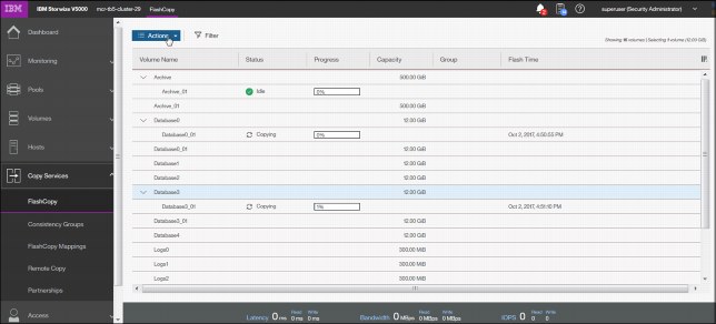
Figure 3-68 FlashCopy operations
If you need to create a FlashCopy of an additional volume, right-click the volume and the list of available functions displays. You can perform several tasks, such as initiate a new snapshot, and clone or back up a volume.
Clicking the volume name opens the window that is shown in Figure 3-69. You can click the tabs at the top of the window to display additional information, such as the hosts that the volume or FlashCopy volume is mapped to and its dependent MDisks.

Figure 3-69 FlashCopy volume details
3.7.2 Consistency group
FlashCopy consistency groups can be used to create a consistent point-in-time copy across multiple volumes, and even across multiple managed storage systems, managing the consistency of dependent writes.
Click Consistency Group to open the window that is shown in Figure 3-70. FlashCopy relationships can be placed into a consistency group. You can also use start and stop commands against the FlashCopy consistency group from this window by right-clicking the relationship.

Figure 3-70 FlashCopy Consistency Groups window
When any FlashCopy consistency group is available, either empty or with existing relationships, you can move an existing relationship to that group. Right-click a relationship and select Move to Consistency Group as shown in Figure 3-71.
Other actions on the same menu include Remove from Consistency Group, Start (resume) or Stop that FlashCopy operation, Rename Mapping (rename a target volume or FlashCopy mapping), and Delete Mapping.

Figure 3-71 Moving a relationship to the consistency group
From the menu, select the appropriate group (in our case, the only one available) and confirm the selection (Figure 3-72).

Figure 3-72 Assigning the consistency group
The result of the operation is similar to the result that is shown in Figure 3-73.

Figure 3-73 Consistency groups
3.7.3 FlashCopy mappings
To create a new FlashCopy mapping, click Create FlashCopy Mapping (shown in Figure 3-74) to start a wizard. This wizard maps a source volume to a target volume to prepare for a subsequent copy. This mapping persists until it is deleted. The mapping specifies the source and destination volumes. The destination must be identical in size to the source or the mapping fails.

Figure 3-74 FlashCopy mappings
In a single mapping, the source and destination cannot be on the same volume. A mapping is triggered at the point in time when the copy is required. The mapping can optionally be given a name and assigned to a consistency group. These groups of mappings can be triggered at the same time, enabling multiple volumes to be copied at the same time, which creates a consistent copy of multiple disks. A consistent copy of multiple disks is required for database products in which the database and log files are on separate disks.
If a consistency group (ID or Name) is not specified, the mapping is assigned to the default group 0, which is a special group that cannot be started as a whole. Mappings in this group can be started only on an individual basis.
An example of the wizard for FlashCopy mapping creation is shown in Figure 3-75. Select source and target volumes from the wizard.

Figure 3-75 Selecting volumes for FlashCopy mappings
You can select the Snapshot (copy-on-write), Clone (replica of the volume without effect on original one), or Backup (data recovery) type of relationship. When selected, you can specify whether you also want to add the mapping to the consistency group.
3.7.4 Remote copy
Click Remote Copy to open the window that is shown in Figure 3-76. This window shows the existing remote copy relationships, and you can set up and modify consistency groups. From this window, you can also start and stop relationships, add relationships to a consistency group, and switch the direction of the mirror.

Figure 3-76 Remote Copy window
The menu provides the options to create Metro Mirror, Global Mirror, or Global Mirror with Changed Volumes:
Metro Mirror This option makes synchronous copies. The original write operations are not considered complete until the write operation to the destination disk is confirmed. The distance between your two sites is determined by how much latency your applications can handle.
Global Mirror This option makes asynchronous copies of your disk. The write is considered complete after it is complete at the local disk. It does not wait for the write to be confirmed at the remote cluster as Metro Mirror does. This method greatly reduces the latency that is experienced by your applications if the other cluster is far away.
However, it also means that during a failure, the data on the remote copy might not contain the most recent changes that were committed to the local disk.
Global Mirror with Changed Volumes
This option is best described as “Continuous Remote FlashCopy.” If you use this feature, IBM Spectrum Virtualize essentially takes a periodic FlashCopy of a disk and writes it to your remote destination. This feature completely isolates the local copy from wide area network (WAN) issues and from sudden spikes in workload that might occur.
The drawback is that your remote copy might lag behind the original
by a significant amount of data, depending on how you set up the cycle time.
by a significant amount of data, depending on how you set up the cycle time.
3.7.5 Partnerships
Click Partnerships to open the window that is shown in Figure 3-77. You can use this window to set up a new partnership, or delete an existing partnership for remote mirroring with another Storwize V5000 system. To create a partnership, click Create Partnership. A new window displays. When you select the partnership type, for example, Fibre Channel, the window expands to a more detailed view, as shown in Figure 3-77.

Figure 3-77 Creating a partnership
Clicking an existing partnership opens a window, as shown in Figure 3-78. From this window, you can also set the background copy rate. This rate specifies the bandwidth, in Mbps, that is used by the background copy process between the clusters (Figure 3-78). In our case, we configured the partnership only on one side.
You can see it in the State row. It shows Partially Configured: Local, which is an indication that the configuration was only configured on one side. If you see this message, go to the second system, and configure the Create Partnership settings there, too.

Figure 3-78 Partnership properties
3.8 Access menu
The Access menu has two options:
•Users (for user management)
•Audit Log
Figure 3-79 shows these options.

Figure 3-79 Access menu
3.8.1 Users
Figure 3-80 shows the Users pane. You can create and delete new users, change and remove passwords, and add and remove Secure Shell (SSH) keys.

Figure 3-80 Users window
Click Create User to open the pane that is shown in Figure 3-81. Use this pane to specify the name and password of the user, and load the SSH key (if the SSH key was generated). SSH key is not required for CLI access, and you can choose to use either SSH or a password for CLI authentication.

Figure 3-81 Adding a user
3.8.2 Audit Log option
Click Audit Log to open the window that is shown in Figure 3-82 on page 132. The cluster maintains an audit log of successfully run commands and displays the users that performed particular actions at certain times.

Figure 3-82 Audit Log entries
You can filter audit log records by date or within a specific time frame (Figure 3-83).

Figure 3-83 Filtering the records
The following commands are not recorded in the audit log:
•All commands that failed
•dumpconfig
•cpdumps
•cleardumps
•finderr
•dumperrlog
•dumpinternallog
•svcservicetask dumperrlog
•svcservicetask finderr
3.9 Settings menu
The Settings menu provides various options to adjust your system parameters according to your needs. You can configure these options (Figure 3-84):
•Notifications
•Network
•Security (remote authentication)
•System
•Support
•GUI Preferences

Figure 3-84 Settings menu
3.9.1 Notifications
It is important to correct any issues that are reported by your IBM Spectrum Virtualize system as soon as possible. Configure your system to send automatic notifications when a new event is reported. To avoid monitoring for new events that use the management GUI, select the type of event that you want to be notified about, for example, restrict notifications to events that require immediate action.
You can use email, Simple Network Management Protocol (SNMP), or syslog types of notifications. If your system is within warranty, or if you use a hardware maintenance agreement, configure your Storwize V5000 system to send email events to IBM directly if an issue that requires hardware replacement is detected. This mechanism is called Call Home.
When an event is received, IBM automatically opens a problem report. If appropriate, IBM contacts you to verify whether replacement parts are required. The configuration window for e-mail notifications is shown in Figure 3-85.

Figure 3-85 Email event notifications
The procedure for how to enable e-mail notifications is described in Chapter 12, “RAS, monitoring, and troubleshooting” on page 653.
3.9.2 Network
Click Network to open the window that is shown in Figure 3-86. You can update the network configuration, set up iSCSI definitions, and view information about the Fibre Channel connections.

Figure 3-86 Network window
When you click Fibre Channel Connectivity (Figure 3-87), useful information is displayed. In this example, we click All nodes, storage systems, and hosts from the menu and then select Show Results to display the details. Other options that are available from the menu include displaying Fibre Channel details for a host, clusters, nodes, or storage systems.

Figure 3-87 Fibre Channel connectivity
3.9.3 Security
The different security features are described below.
Remote authentication
With security and its directory services, the user can remotely authenticate to the IBM Spectrum Virtualize without the need for a local account. Therefore, when you log on, you authenticate with your domain user ID and password rather than a locally created user ID and password.
The benefits of remote authentication are listed:
•You do not need to configure every user on every IBM Spectrum Virtualize. If multiple machines are in your environment, you can set up authentication more efficiently.
•When commands are run on the IBM Spectrum Virtualize, the audit log shows the domain user name that issued that command, rather than a local user name, or worse, just “superuser”. (In this case, determining who mapped a volume, acted as the superuser, and so on, might be difficult.)
•You have central control over access. If someone leaves the company, you simply remove access at the domain controller, which means that orphan accounts do not remain on your storage equipment.
The access pane to configure remote authentication is shown in Figure 3-88.

Figure 3-88 Configuring remote authentication
The detailed steps to configure remote logon are described at the following addresses:
Encryption
On the panel that is shown in Figure 3-89, you can enable or disable the encryption function on an IBM Storwize V5030. The panel shows that no USB drives that contain encryption keys were detected. These are no longer needed if you have an external Key Management Server. Figure 3-89 shows four available external Key Management Server. If there is no external Server available, you need the USB keys to be able to en/decrypt your data on power on.
External Encryption Management server is implemented in the IBM Spectrum Virtualize code V8.1.
Figure 3-89 Encryption panel
Secure communications
Use the Secure Communications page to enable and manage secure connections. During system setup, an initial certificate is created to use for secure connections between web browsers. Based on the security requirements for your system, you can create either a new self-signed certificate or install a signed certificate that is created by a third-party certificate authority.
Self-signed certificates are generated automatically by the system and encrypt communications between the browser and the system. Self-signed certificates can generate web browser security warnings, and they might not comply with organizational security guidelines. Signed certificates are created by a third-party certificate authority. These certificate authorities ensure that certificates have the required security level for an organization based on purchase agreements. Signed certificates usually have higher security controls for the encryption of data and do not cause browser security warnings.
To use a signed certificate, first generate and download a request for a certificate that is based on the values that are specified on the Secure Communication page. Submit this request to the certificate authority to receive a signed certificate and then install it by using the Secure Communication page. Before you create a request for either type of certificate, ensure that your current browser does not restrict the type of keys that are used for certificates. Certain browsers limit the use of specific key types for security and compatibility.
On Figure 3-90, you can see the details about the security certificates.

Figure 3-90 Secure communications
If you want to update or change the certificate, click Update Certificate.
The Update Certificate panel opens, as shown in Figure 3-91.

Figure 3-91 Update Certificate panel
3.9.4 System
The System menu provides the following options:
•Set the system date and time
•Manage licenses
•Upgrade System
•Virtual Volumes (VVols)
•IP Quorum
•I/O Groups
•DNS
The Date and Time window opens (Figure 3-92) when you select Date and Time from the System menu. You can add a Network Time Protocol (NTP) server if available.

Figure 3-92 Date and Time window
You can also update the license information for specific features, as shown in Figure 3-93.

Figure 3-93 Licensing options
To upgrade your IBM Spectrum Virtualize, use the procedure that is described in Chapter 12, “RAS, monitoring, and troubleshooting” on page 653.
Virtual Volume (VVol) is a tape volume that resides in a tape volume cache of a virtual tape server (VTS). VVol is a new feature that was introduced in IBM Spectrum Virtualize 7.6. With this new functionality, users can create volumes on IBM Spectrum Virtualize directly from a VMware VCenter server.
On the VVOL page, you can enable or disable the functionality, as shown in Figure 3-94. Before you can enable VVol, you must set up an NTP server. See the Date and Time settings to set up the NTP server.

Figure 3-94 Activating VVol
In some HyperSwap configurations, IP quorum applications can be used at the third site as an alternative to third-site quorum disks. No Fibre Channel connectivity at the third site is required to use an IP quorum application as the quorum device. The IP quorum application is a Java application that runs on a host at the third site. The IP network is used for communication between the IP quorum application and node canisters in the system.
If you currently have a third-site quorum disk, you must remove the third site before you use an IP quorum application. The round trip time limitations from 80 micro seconds for a IP quorum are still existent. Figure 3-95 shows where you can download the Java application.

Figure 3-95 IP Quorum
For ports within an I/O group, you can enable virtualization of Fibre Channel ports that are used for host I/O operations. With N_Port ID virtualization (NPIV), the Fibre Channel port consists of both a physical port and a virtual port. When port virtualization is enabled, ports do not come up until they are ready to handle I/O, which improves host behavior around node unpends. In addition, path failures due to an offline node are masked from hosts. The target port mode on the I/O group indicates the current state of port virtualization. Figure 3-96 shows the panel with the I/O Groups.

Figure 3-96 I/O Groups
Domain Name System (DNS) translates IP address to host names. You can create, delete, or change domain name servers, which manage names of resources that are located on external networks.
You can have up to two DNS servers that are configured on the system. To configure DNS for the system, enter a valid IP address and name for each server. Both IPv4 and IPv6 address formats are supported. Figure 3-97 shows the DNS setup Window.

Figure 3-97 DNS
3.9.5 Support
Support assistance enables support personnel to access the system to complete troubleshooting and maintenance tasks. You can configure either local support assistance, where support personnel visit your site to fix problems with the system, or remote support assistance. Both local and remote support assistance uses secure connections to protect data exchange between the support center and system. To enable Support assistance you need to enable an email Server. More access controls can be added by the system administrator. Figure 3-98 shows the Support assistance panel.

Figure 3-98 Support assistance
If support assistance is configured on your system, you can either automatically or manually upload new support packages to the support center to help analyze and resolve errors on the system. You can select individual logs to either download to review or send directly to the support center for analysis. Figure 3-99 shows how to upload or download support logs.

Figure 3-99 Up- or downloading support packages
For more information, see Chapter 12, “RAS, monitoring, and troubleshooting” on page 653.
3.9.6 GUI preferences
By using this menu, you can configure the appearance and behavior of the GUI. Click GUI Preferences in the Settings option of the Dynamic menu. To display the login message, select Enable. You can create a customized login message, as shown in Figure 3-100.

Figure 3-100 GUI preferences
Select General to adjust the browser settings, as shown in Figure 3-101.

Figure 3-101 General settings
..................Content has been hidden....................
You can't read the all page of ebook, please click here login for view all page.