Chapter 2. The MorphX development environment and tools
In this chapter
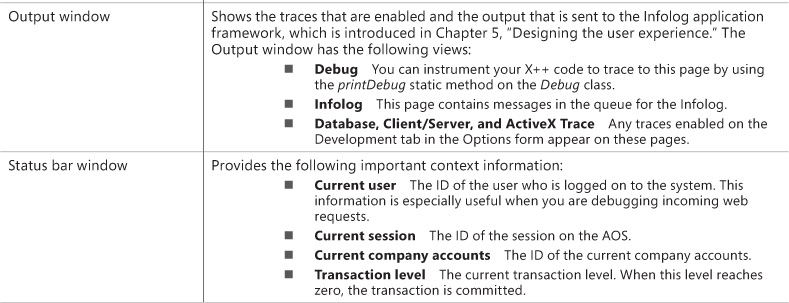
Introduction
AX 2012 includes a set of tools, the MorphX development tools, that you can use to build and modify AX 2012 business applications. Each feature of a business application uses the application model elements described in Chapter 1, “Architectural overview.” With the MorphX tools, you can create, view, modify, and delete the application model elements, which contain metadata, structure (ordering and hierarchies of elements), properties (key and value pairs), and X++ code. For example, a table element includes the name of the table, the properties set for the table, the fields, the indexes, the relations, and the methods, among other things.
This chapter describes the most commonly used tools and offers some tips and tricks for working with them. You can find additional information and an overview of other MorphX tools in the MorphX Development Tools section of the AX 2012 software development kit (SDK) on the Microsoft Developer Network (MSDN).
To enable development mode in AX 2012, press Ctrl+Shift+W to launch the Development Workspace, which holds all of the development tools.
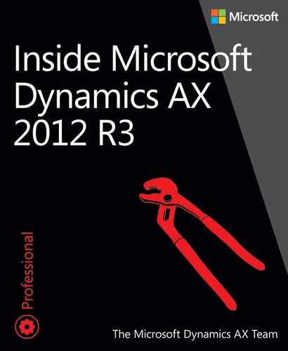
Table 2-1 lists the MorphX tools and components.
You can access these development tools from the following places:
![]() In the Development Workspace, on the Tools menu
In the Development Workspace, on the Tools menu
![]() On the context menus of elements in the AOT
On the context menus of elements in the AOT
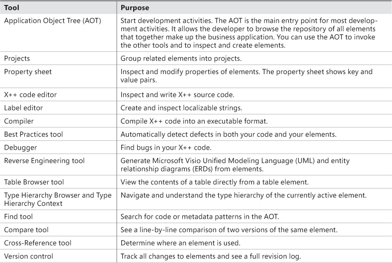
You can personalize the behavior of many MorphX tools by clicking Options on the Tools menu. Figure 2-1 shows the Options form.
Application Object Tree
The AOT is the main entry point to MorphX and the repository explorer for all metadata. You can open the AOT by clicking the AOT icon on the toolbar or by pressing Ctrl+D. The AOT icon looks like this:
Navigating through the AOT
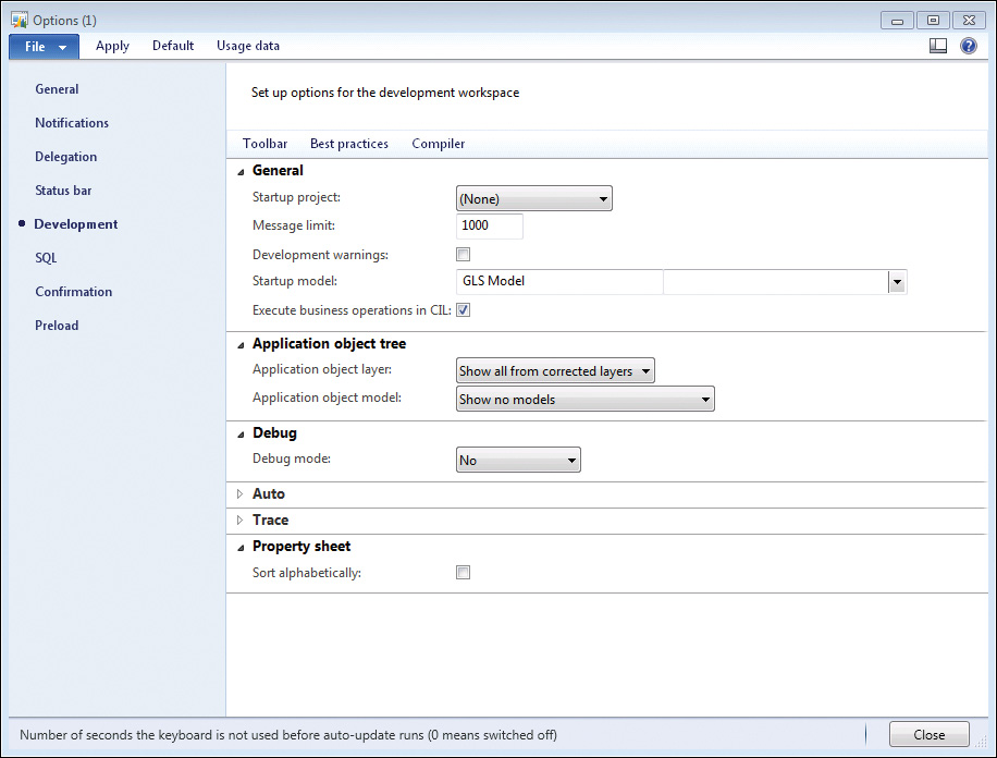
As the name implies, the AOT is a tree view. The root of the AOT contains the element categories, such as Classes, Tables, and Forms. Some elements are grouped into subcategories to provide a better structure. For example, Tables, Maps, Views, and Extended Data Types are located under Data Dictionary, and all web-related elements are located under Web. Figure 2-2 shows the AOT.
You can navigate through the AOT by using the arrow keys on the keyboard. Pressing the Right Arrow key expands a node if it has any children.
Elements are arranged alphabetically. Because there are thousands of elements, it’s important to understand the naming conventions and adhere to them to use the AOT effectively.
All element names in the AOT use the following structure:
<Business area name> + <Functional area> + <Functionality, action performed, or type of content>
With this naming convention, similar elements are placed next to each other. The business area name is also often referred to as the prefix. Prefixes are commonly used to indicate the team responsible for an element. For example, in the name VendPaymReconciliationImport, the prefix Vend is an abbreviation of the business area name (Vendor), PaymReconciliation describes the functional area (payment reconciliation), and Import lists the action performed (import). The name CustPaymReconciliationImport describes a similar functional area and action for the Customer business area.
![]() Tip
Tip
When building add-on functionality, in addition to following this naming convention, you should add another prefix that uniquely identifies the solution. This additional prefix will help prevent name conflicts if your solution is combined with work from other sources. Consider using a prefix that identifies the company and the solution. For example, if a company called MyCorp is building a payroll system, it could use the prefix McPR on all elements added.
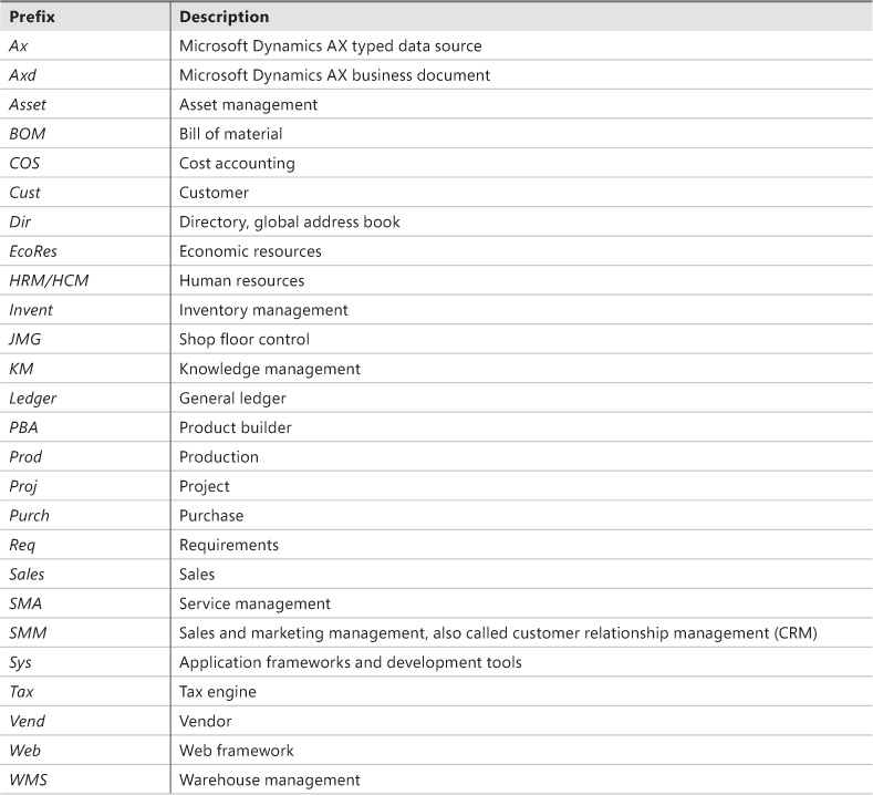
Table 2-2 contains a list of the most common prefixes and their descriptions.
![]() Tip
Tip
When creating new elements, ensure that you follow the recommended naming conventions. Any future development and maintenance will be much easier.
Projects, described in detail later in this chapter, provide an alternative view of the information in the AOT.
Creating elements in the AOT
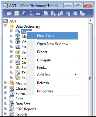
You can create new elements in the AOT by right-clicking the element category node and selecting New <Element Type>, as shown in Figure 2-3.
Elements are given automatically generated names when they are created. However, you should replace the default names with new names that conform to the naming convention.
Modifying elements in the AOT
Each node in the AOT has a set of properties and either subnodes or X++ code. You can use the property sheet (shown in Figure 2-9, later in this chapter) to inspect or modify properties, and you can use the X++ code editor (shown in Figure 2-11, later in this chapter) to inspect or modify X++ code.
The order of the subnodes can play a role in the semantics of the element. For example, the tabs on a form appear in the order in which they are listed in the AOT. You can change the order of nodes by selecting a node and pressing the Alt key while pressing the Up Arrow or Down Arrow key.
A red vertical line next to a root element name marks it as modified and unsaved, or dirty, as shown in Figure 2-4.
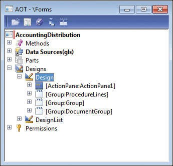
FIGURE 2-4 A dirty element in the AOT, indicated by a vertical line next to the top-level node, AccountingDistribution.
A dirty element is saved in the following situations:
![]() When the element is executed.
When the element is executed.
![]() When the developer explicitly invokes the Save or Save All action.
When the developer explicitly invokes the Save or Save All action.
![]() When autosave takes place. You specify the frequency of autosave in the Options form, which is accessible from the Tools menu.
When autosave takes place. You specify the frequency of autosave in the Options form, which is accessible from the Tools menu.
Refreshing elements in the AOT
If several developers modify elements simultaneously in the same installation of AX 2012, each developer’s local elements might not be synchronized with the latest version. To ensure that the local versions of remotely changed elements are updated, an autorefresh thread runs in the background. This autorefresh functionality eventually updates all changes, but you might want to force the refresh of an element explicitly. You do this by right-clicking the element, and then clicking Restore. This action refreshes both the on-disk and the in-memory versions of the element.
Typically, the general integrity of what’s shown in the AOT is managed automatically, but some operations, such as restoring the application database or reinstalling the application, can lead to inconsistencies that require manual resolution to ensure that the latest elements are used. To perform manual resolution, follow these steps:
1. Close the AX 2012 client to clear any in-memory elements.
2. Stop the Microsoft Dynamics Server service on the Application Object Server (AOS) to clear any in-memory elements.
3. Delete the application element cache files (*.auc) from the Local Application Data folder (located in %LocalAppData%) to remove the on-disk elements.
Element actions in the AOT
Each node in the AOT contains a set of available actions. You can access these actions from the context menu, which you can open by right-clicking any node.
Here are two facts to remember about actions:
![]() The actions that are available depend on the type of node you select.
The actions that are available depend on the type of node you select.
![]() You can select multiple nodes and perform actions simultaneously on all the nodes selected.
You can select multiple nodes and perform actions simultaneously on all the nodes selected.
A frequently used action is Open New Window, which is available for all nodes. It opens a new AOT window with the current node as the root. This action was used to create the screen capture of the AccountingDistribution element shown earlier in Figure 2-4. After you open a new AOT window, you can drag elements into the nodes, saving time and effort when you’re developing an application.
You can extend the list of available actions on the context menu. You can create custom actions for any element in the AOT by using the features provided by MorphX. In fact, all actions listed on the Add-Ins submenu are implemented in MorphX by using X++ and the MorphX tools.
You can enlist a class as a new add-in by following this procedure:
1. Create a new menu item and give it a meaningful name, a label, and Help text.
2. Set the menu item’s Object Type property to Class.
3. Set the menu item’s Object property to the name of the class to be invoked by the add-in.
4. Drag the menu item to the SysContextMenu menu.
5. If you want the action to be available only for certain nodes, modify the verifyItem method on the SysContextMenu class.
Element layers and models in the AOT
When you modify an element from a lower layer, a copy of the element is placed in the current layer and the current model. All elements in the current layer appear in bold type (as shown in Figure 2-5), which makes it easy to recognize changes. For a description of the layer technology, see the “Layers” section in Chapter 21, “Application models.”
You can use the Application object layer and Application object model settings in the Options form to personalize the information shown after the element name in the AOT (see Figure 2-1, shown earlier). Figure 2-5 shows a class with the Show All Layers option set. As you can see, each method is suffixed with information about the layers in which it is defined, such as SYS, VAR, and USR. If an element exists in several layers, you can right-click it and then click Layers to access its versions from lower layers. It is highly recommended that you use the Show All Layers setting during code upgrade because it provides a visual representation of the layer dimension directly in the AOT.
Projects
For a fully customizable overview of the elements, you can use projects. In a project, you can group and structure elements according to your preference. A project is a powerful alternative to the AOT because you can collect all the elements needed for a feature in one project.
Creating a project
You open projects from the AOT by clicking the Project icon on the toolbar. Figure 2-6 shows the Projects window and its Private and Shared projects nodes.
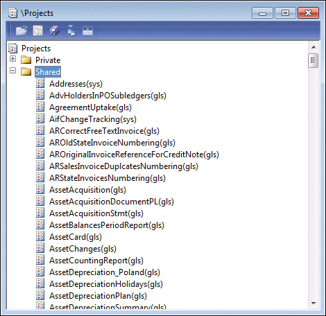
Except for its structure, a project generally behaves like the AOT. Every element in a project is also present in the AOT.
When you create a new project, you must decide whether it should be private or shared among all developers. You can’t set access requirements on shared projects. You can make a shared project private (and a private project shared) by dragging it from the shared category into the private category.
![]() Note
Note
Central features of AX 2012 are captured in shared projects to provide an overview of all the elements in a feature. No private projects are included with the application.
You can specify a startup project in the Options form. If specified, the chosen project automatically opens when AX 2012 is started.
Automatically generating a project
Projects can be automatically generated in several ways—from using group masks to customizing project types—to make working with them easier. The following sections outline the various ways to generate projects automatically.
Group masks
Groups are folders in a project. When you create a group, you can have its contents be automatically generated by setting the ProjectGroupType property (All is an option) and providing a regular expression as the value of the GroupMask property. The contents of the group are created automatically and are kept up to date as elements are created, deleted, and renamed. Using group masks ensures that your project is always current, even when elements are created directly in the AOT.
Figure 2-7 shows the ProjectGroupType property set to Classes and the GroupMask property set to ReleaseUpdate on a project group. All classes with names containing ReleaseUpdate (the prefix for data upgrade scripts) will be included in the project group.
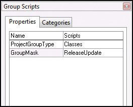
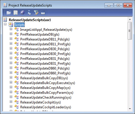
Figure 2-8 shows the resulting project when the settings from Figure 2-7 are used.
Filters
You can also generate a project based on a filter. Because all elements in the AOT persist in a database format, you can use a query to filter elements and have the results presented in a project. You create a project filter by clicking Filter on the project’s toolbar. Depending on the complexity of the query, a project can be generated instantly or it might take several minutes.
With filters, you can create projects containing elements that meet the following criteria:
![]() Elements created or modified within the last month
Elements created or modified within the last month
![]() Elements created or modified by a named user
Elements created or modified by a named user
![]() Elements from a particular layer
Elements from a particular layer
Development tools
Several development tools, such as the Wizard Wizard, produce projects containing elements that the wizard creates. The result of running the Wizard Wizard is a new project that includes a form, a class, and a menu item—all the elements that make up the newly created wizard.
You can also use several other wizards, such as the AIF Document Service Wizard and the Class Wizard, to create projects. To access these wizards, on the Tools menu, click Wizards.
Layer comparison
You can compare the elements in one layer with the elements in another layer, which is called the reference layer. If an element exists in both layers and the definitions of the element are different, or if the element doesn’t exist in the reference layer, the element is added to the resulting project. To compare layers, click Tools > Code Upgrade > Compare Layers.
Upgrade projects
When you upgrade from one version of Microsoft Dynamics AX to another or install a new service pack, you need to deal with any new elements that have been introduced and existing elements that have been modified. These changes might conflict with customizations you’ve implemented in a higher layer.
The Create Upgrade Project feature makes a three-way comparison to establish whether an element has any upgrade conflicts. It compares the original version with both the customized version and the updated version. If a conflict is detected, the element is added to the project.
The resulting project provides a list of elements to update based on upgrade conflicts between versions. You can use the Compare tool, described later in this chapter, to see the conflicts in each element. Together, these features provide a cost-effective toolbox to use when upgrading. For more information about code upgrade, see “Microsoft Dynamics AX 2012 White Papers: Code Upgrade” at http://www.microsoft.com/download/en/details.aspx?id=20864.
To create an upgrade project, click Tools > Code Upgrade > Detect Code Upgrade Conflicts.
Project types
When you create a new project, you can specify a project type. So far, this chapter has discussed standard projects. The Test project, used to group a set of classes for unit testing, is another specialized project type provided in AX 2012.
You can create a custom specialized project by creating a new class that extends the ProjectNode class. With a specialized project, you can control the structure, icons, and actions available to the project.
The property sheet
Properties are an important part of the metadata system. Each property is a key and value pair. You can use the property sheet to inspect and modify properties of elements.
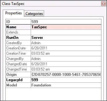
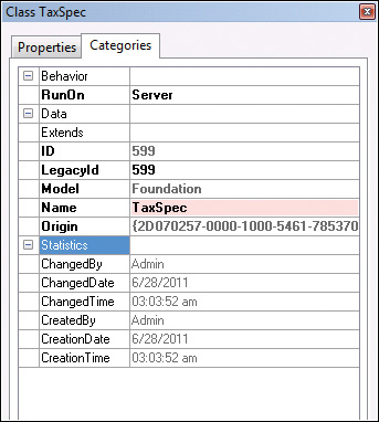
When the Development Workspace opens, the property sheet is visible by default. If you close it, you can open it again anytime by pressing Alt+Enter or by clicking the Properties button on the toolbar of the Development Workspace. The property sheet automatically updates itself to show properties for any element selected in the AOT. You don’t have to open the property sheet manually for each element; you can leave it open and browse the elements. Figure 2-9 shows the property sheet for the TaxSpec class. The two columns are the key and value pairs for each property.
![]() Tip
Tip
Pressing Esc in the property sheet sets the focus back to your origin.
Figure 2-10 shows the Categories tab for the class shown in Figure 2-9. On this tab, related properties are categorized. For elements with many properties, this view can make it easier to find the right property.
Read-only properties appear in gray. Just like files in the file system, elements contain information about who created them and when they were modified. Elements that come from Microsoft all have the same time and user stamps.
The default sort order places related properties near each other. Categories were introduced in an earlier version of Microsoft Dynamics AX to make finding properties easier, but you can also sort properties alphabetically by setting a parameter in the Options form.
You can dock the property sheet on either side of the screen by right-clicking the title bar. Docking ensures that the property sheet is never hidden behind another tool.
X++ code editor
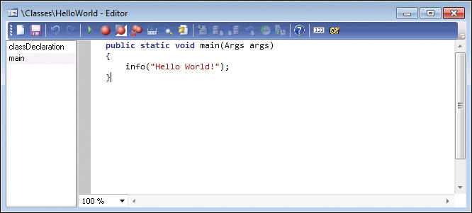
All X++ code is written with the X++ code editor. You open the editor by selecting a node in the AOT and pressing Enter. The editor contains two panes. The left pane shows the methods available, and the right pane shows the X++ code for the selected method, as shown in Figure 2-11.
The X++ code editor is a basic text editor that supports color coding and IntelliSense.
Shortcut keys
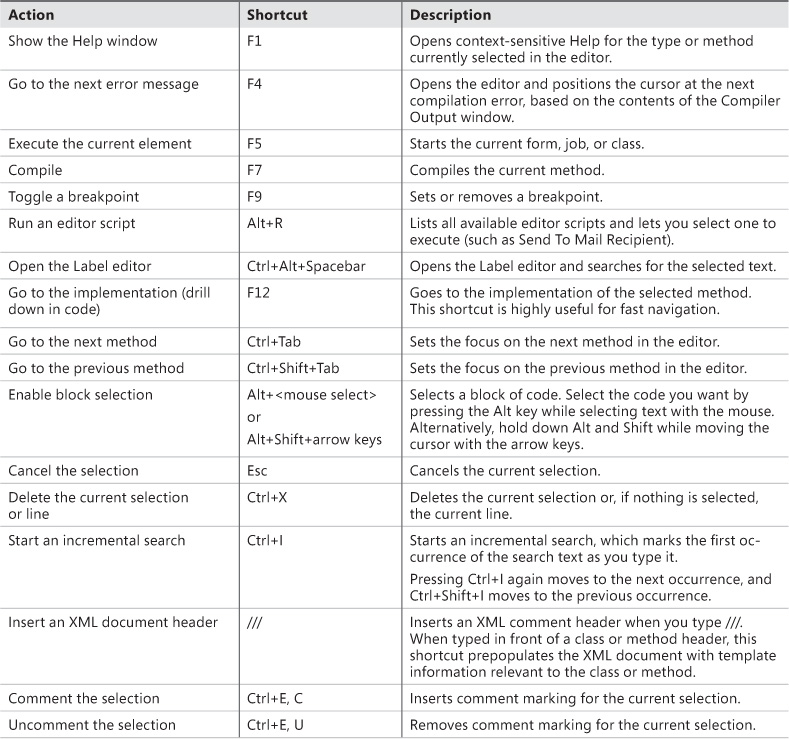
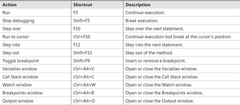
Navigation and editing in the X++ code editor use standard shortcuts, as described in Table 2-3. For AX 2012, some shortcuts differ from those in earlier versions to align with commonly used integrated development environments (IDEs) such as Microsoft Visual Studio.
Editor scripts
The X++ code editor contains a set of editor scripts that you can invoke by clicking the Script icon on the X++ code editor toolbar or by right-clicking an empty line in the code editor, pointing to Scripts, and then clicking the script you want. Built-in editor scripts provide functionality such as the following:
![]() Send to mail recipient.
Send to mail recipient.
![]() Send to file.
Send to file.
![]() Generate code for standard code patterns such as main, construct, and parm methods.
Generate code for standard code patterns such as main, construct, and parm methods.
![]() Open the AOT for the element that owns the method.
Open the AOT for the element that owns the method.
![]() Note
Note
By generating code, in a matter of minutes you can create a new class with the right constructor method and the right encapsulation of member variables by using parm methods. Parm methods (parm is short for “parameter”) are used as simple property getters and setters on classes. Code is generated in accordance with X++ best practices.
![]() Tip
Tip
To add a main method to a class, add a new method, press Ctrl+A to select all code in the editor tab for the new method, type main, and then press the Tab key. This will replace the text in the editor with the standard template for a static main method.
The list of editor scripts is extendable. You can create your own scripts by adding new methods to the EditorScripts class.
Label editor
The term label in AX 2012 refers to a localizable text resource. Text resources are used throughout the product as messages to the user, form control labels, column headers, Help text in the status bar, captions on forms, and text on web forms, to name just a few uses. Labels are localizable, meaning that they can be translated into most languages. Because the space requirement for displaying text resources typically depends on the language, you might fear that the actual user interface must be manually localized as well. However, with IntelliMorph technology, the user interface is dynamically rendered and honors any space requirements imposed by localization.
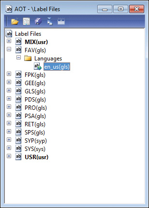
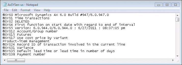
The technology behind the label system is simple. All text resources are kept in a Unicode-based label files that are named with three-letter identifiers. In AX 2012, the label files are managed in the AOT and distributed by using model files. Figure 2-12 shows how the Label Files node in the AOT looks with multiple label files and the en-us language identifier.
The underlying source representation is a simple text file that follows this naming convention:
Ax<Label file identifier><Locale>.ALD
The following are two examples, the first showing a U.S. English label file and the second a Danish label file:
Axsysen-us.ALD
Axtstda.ALD
Each text resource in the label file has a 32-bit integer label ID, label text, and an optional label description. The structure of the label file is simple:
@<Label ID><Label text>
[Label description]
Figure 2-13 shows an example of a label file.
This simple structure allows for localization outside of AX 2012 with third-party tools. The AOT provides a set of operations for the label files, including an Export To Label file that can be used to extract a file for external translation.
You can create new label files by using the Label File Wizard, which you access directly from the Label Files node in the AOT, or from the Tools menu by pointing to Wizards > Label File Wizard. The wizard guides you through the steps of adding a new label file or a new language to an existing label file. After you run the wizard, the label file is ready to use. If you have an existing .ald file, you can also create the appropriate entry in the AOT by using Create From File on the context menu of the Label Files node in the AOT.
![]() Note
Note
You can use any combination of three letters when naming a label file, and you can use any label file from any layer. A common misunderstanding is that the label file identifier must match the layer in which it is used. AX 2012 includes a SYS layer and a label file named SYS; service packs contain a SYP layer and a label file named SYP. This naming standard was chosen because it is simple, easy to remember, and easy to understand. However, AX 2012 doesn’t impose any limitations on the label file name.
Consider the following tips for working with label files:
![]() When naming a label file, choose a three-letter ID that has a high chance of being unique, such as your company’s initials. Don’t choose the name of the layer, such as VAR or USR. Eventually, you’ll probably merge two separately developed features into the same installation, a task that will be more difficult if the label file names collide.
When naming a label file, choose a three-letter ID that has a high chance of being unique, such as your company’s initials. Don’t choose the name of the layer, such as VAR or USR. Eventually, you’ll probably merge two separately developed features into the same installation, a task that will be more difficult if the label file names collide.
![]() When referencing existing labels, feel free to reference labels in the label files provided by Microsoft, but avoid making changes to labels in these label files because they are updated with each new version of Microsoft Dynamics AX.
When referencing existing labels, feel free to reference labels in the label files provided by Microsoft, but avoid making changes to labels in these label files because they are updated with each new version of Microsoft Dynamics AX.
Creating a label
You use the Label editor to create new labels. You can start the Label editor by using any of the following procedures:
![]() On the Tools menu, point to Label > Label Editor.
On the Tools menu, point to Label > Label Editor.
![]() On the X++ code editor toolbar, click the Lookup Label > Text button.
On the X++ code editor toolbar, click the Lookup Label > Text button.
![]() On text properties in the property sheet, click the Lookup button.
On text properties in the property sheet, click the Lookup button.
You can use the Label editor (shown in Figure 2-14) to find existing labels. Reusing a label is sometimes preferable to creating a new one. You can create a new label by pressing Ctrl+N or by clicking New.
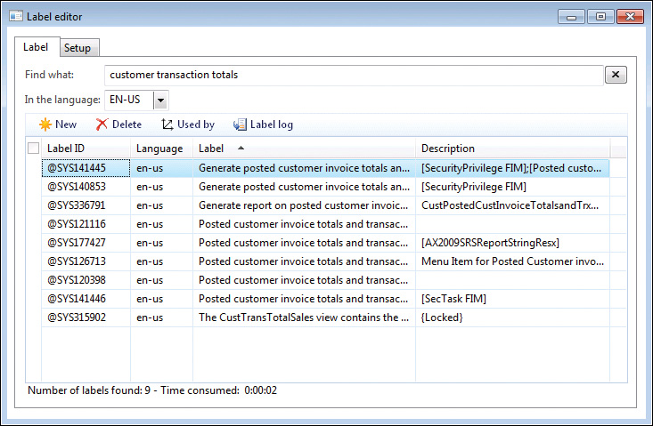
In addition to finding and creating new labels, you can use the Label editor to find out where a label is used. The Label editor also logs any changes to each label.
Consider the following tips when creating and reusing labels:
![]() When reusing a label, make sure that the label means what you intend it to in all languages. Some words are homonyms (words that have many meanings), and they naturally translate into many different words in other languages. For example, the English word can is both a verb and a noun. Use the description column to note the intended meaning of the label.
When reusing a label, make sure that the label means what you intend it to in all languages. Some words are homonyms (words that have many meanings), and they naturally translate into many different words in other languages. For example, the English word can is both a verb and a noun. Use the description column to note the intended meaning of the label.
![]() When creating a new label, ensure that you use complete sentences or other stand-alone words or phrases. Don’t construct complete sentences by concatenating labels with one or two words because the order of words in a sentence differs from one language to another.
When creating a new label, ensure that you use complete sentences or other stand-alone words or phrases. Don’t construct complete sentences by concatenating labels with one or two words because the order of words in a sentence differs from one language to another.
Referencing labels from X++
In the MorphX design environment, labels are referenced in the format @<LabelFileIdentifier> <LabelID>. If you don’t want a label reference to be converted automatically to the label text, you can use the literalStr function. When a placeholder is needed to display the value of a variable, you can use the strFmt function and a string containing %n, where n is greater than or equal to 1. Placeholders can also be used within labels. The following code shows a few examples:
// prints: Time transactions
print "@SYS1";
// prints: @SYS1
print literalStr("@SYS1");
// prints: Microsoft Dynamics is a Microsoft brand
print strFmt("%1 is a %2 brand", "Microsoft Dynamics", "Microsoft");
pause;
The following are some best practices to consider when referencing labels from X++:
![]() Always create user interface text by using a label. When referencing labels from X++ code, use double quotation marks.
Always create user interface text by using a label. When referencing labels from X++ code, use double quotation marks.
![]() Never create system text such as file names by using a label. When referencing system text from X++ code, use single quotation marks. You can place system text in macros to make it reusable.
Never create system text such as file names by using a label. When referencing system text from X++ code, use single quotation marks. You can place system text in macros to make it reusable.
Using single and double quotation marks to differentiate between system text and user interface text allows the Best Practices tool to find and report any hard-coded user interface text. The Best Practices tool is described in depth later in this chapter.
Compiler
Whenever you make a change to X++ code, you must recompile, just as you would in any other programming language. You start the recompile by pressing F7 in the X++ code editor. Your code also recompiles whenever you close the editor or save changes to an element.
The compiler also produces a list of the following information:
![]() Compiler errors These prevent code from compiling and should be fixed as soon as possible.
Compiler errors These prevent code from compiling and should be fixed as soon as possible.
![]() Compiler warnings These typically indicate that something is wrong in the implementation. See Table 2-4, later in this section, for a list of example compiler warnings. Compiler warnings can and should be addressed. Check-in attempts with compiler warnings are rejected unless specifically allowed in the version control system settings.
Compiler warnings These typically indicate that something is wrong in the implementation. See Table 2-4, later in this section, for a list of example compiler warnings. Compiler warnings can and should be addressed. Check-in attempts with compiler warnings are rejected unless specifically allowed in the version control system settings.
![]() Tasks (also known as to-dos) The compiler picks up single-line comments that start with TODO. These comments can be useful during development for adding reminders, but you should use them only in cases in which implementation can’t be completed. For example, you might use a to-do comment when you’re waiting for a check-in from another developer. Be careful when using to-do comments to postpone work, and never release code unless all to-dos are addressed. For a developer, there is nothing worse than debugging an issue and finding a to-do comment indicating that the issue was already known but overlooked.
Tasks (also known as to-dos) The compiler picks up single-line comments that start with TODO. These comments can be useful during development for adding reminders, but you should use them only in cases in which implementation can’t be completed. For example, you might use a to-do comment when you’re waiting for a check-in from another developer. Be careful when using to-do comments to postpone work, and never release code unless all to-dos are addressed. For a developer, there is nothing worse than debugging an issue and finding a to-do comment indicating that the issue was already known but overlooked.
![]() Best practice deviations The Best Practices tool carries out more complex validations. For more information, see the “Best Practices tool” section later in this chapter.
Best practice deviations The Best Practices tool carries out more complex validations. For more information, see the “Best Practices tool” section later in this chapter.
Unlike other languages, X++ requires that you compile only code you’ve modified, because the intermediate language the compiler produces is persisted along with the X++ code and metadata. Of course, your changes can require other methods that consume your code to be changed and recompiled if, for example, you rename a method or modify its parameters. If the consumers are not recompiled, a run-time error is thrown when they are invoked. This means that you can execute your business application even when compile errors exist, as long as you don’t use the code that can’t compile. Always ensure that you compile the entire AOT when you consider your changes complete, and fix any compilation errors found. If you’re changing the class declaration somewhere in a class hierarchy, all classes deriving from the changed class should be recompiled, too. This can be achieved by using the Compile Forward option under Add-Ins in the context menu for the changed class node.
The Compiler Output window provides access to every issue found during compilation, as shown in Figure 2-15. The window presents one list of all relevant errors, warnings, best practice deviations, and tasks. Each type of message can be disabled or enabled by using the respective buttons. Each line in the list contains information about each issue that the compiler detects, a description of the issue, and its location.
You can export the contents of the Compiler Output window. This capability is useful if you want to share the list of issues with team members. The exported file is an HTML file that can be viewed in Internet Explorer or reimported into the Compiler Output window in another AX 2012 session.
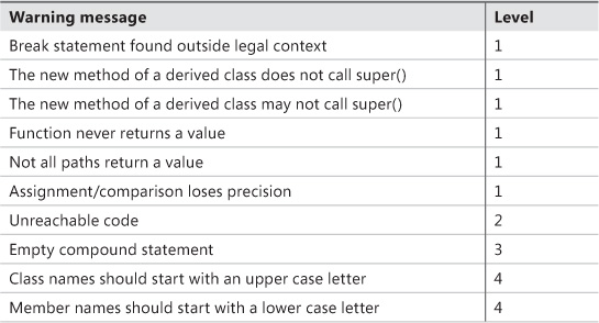
In the Compiler Output window, click Setup > Compiler to define the types of issues that the compiler should report. Compiler warnings are grouped into four levels, as shown by the examples in Table 2-4. Each level represents a certain level of severity, with 1 being the most critical and 4 being recommended to comply with best practices.
Best Practices tool
Following Microsoft Dynamics AX best practices when you develop applications has several important benefits:
![]() You avoid less-than-obvious pitfalls. Following best practices helps you avoid many obstacles, even those that appear only in borderline scenarios that would otherwise be difficult and time consuming to detect and test. Using best practices allows you to take advantage of the combined experience of Microsoft Dynamics AX expert developers.
You avoid less-than-obvious pitfalls. Following best practices helps you avoid many obstacles, even those that appear only in borderline scenarios that would otherwise be difficult and time consuming to detect and test. Using best practices allows you to take advantage of the combined experience of Microsoft Dynamics AX expert developers.
![]() Your learning curve is flattened. When you perform similar tasks in a standard way, you are more likely to be comfortable in an unknown area of the application. Consequently, adding new resources to a project is more cost effective, and downstream consumers of the code can make changes more readily.
Your learning curve is flattened. When you perform similar tasks in a standard way, you are more likely to be comfortable in an unknown area of the application. Consequently, adding new resources to a project is more cost effective, and downstream consumers of the code can make changes more readily.
![]() You are making a long-term investment. Code that conforms to standards is less likely to require rework during an upgrade process, whether you’re upgrading to AX 2012, installing service packs, or upgrading to future releases.
You are making a long-term investment. Code that conforms to standards is less likely to require rework during an upgrade process, whether you’re upgrading to AX 2012, installing service packs, or upgrading to future releases.
![]() You are more likely to ship on time. Most of the problems developers face when implementing a solution in Microsoft Dynamics AX have been solved at least once before. Choosing a proven solution results in faster implementation and less regression. You can find solutions to known problems in both the Developer Help section of the SDK and in the code base.
You are more likely to ship on time. Most of the problems developers face when implementing a solution in Microsoft Dynamics AX have been solved at least once before. Choosing a proven solution results in faster implementation and less regression. You can find solutions to known problems in both the Developer Help section of the SDK and in the code base.
The AX 2012 SDK contains an important discussion about conforming to best practices in AX 2012. Constructing code that follows proven standards and patterns can’t guarantee a project’s success, but it minimizes the risk of failure because of late, expensive discovery, and it decreases the long-term maintenance cost. The AX 2012 SDK is available at http://msdn.microsoft.com/en-us/library/aa496079.aspx.
The Best Practices tool is a powerful supplement to the best practices discussion in the SDK. This tool is the MorphX version of a static code analysis tool, similar to FxCop for the Microsoft .NET Framework. The Best Practices tool is embedded in the compiler, and the results are reported in the Compiler Output window the same way as other messages from the compilation process.
The purpose of static code analysis is to detect defects and risky coding patterns in the code automatically. The longer a defect exists, the more costly it becomes to fix—a bug found in the design phase is much cheaper to correct than a bug in shipped code running at several customer sites. The Best Practices tool allows any developer to run an analysis of his or her code and application model to ensure that it conforms to a set of predefined rules. Developers can run analysis during development, and they should always do so before implementations are tested. Because an application in AX 2012 is much more than just code, the Best Practices tool also performs static analysis on the metadata—the properties, structures, and relationships that are maintained in the AOT.
The Best Practices tool displays deviations from the best practice rules, as shown earlier in Figure 2-15. Double-clicking a line on the Best Practices tab opens the X++ code editor on the violating line of code or, if the Best Practices violation is related to metadata, it will open the element in an AOT window.
Rules
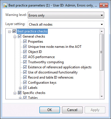
The Best Practices tool includes about 400 rules, a small subset of the best practices mentioned in the SDK. You can define the best practice rules that you want to run in the Best Practice Parameters dialog box: on the Tools menu, click Options > Development, and then click Best Practices.
![]() Note
Note
You must set the compiler error level to 4 if you want best practice rule violations to be reported. To turn off best practice violation reporting, in the Compiler Output window, click Setup > Compiler, and then set the compiler error level to less than 4.
The best practice rules are divided into categories. By default, all categories are turned on, as shown in Figure 2-16.
The best practice rules are divided into three levels of severity:
![]() Errors The majority of the rules focus on errors. Any check-in attempt with a best practice error is rejected. You must take all errors seriously and fix them as soon as possible.
Errors The majority of the rules focus on errors. Any check-in attempt with a best practice error is rejected. You must take all errors seriously and fix them as soon as possible.
![]() Warnings Following a 95/5 rule for warnings is recommended. This means that you should treat 95 percent of all warnings as errors; the remaining 5 percent constitute exceptions to the rule. You should provide valid explanations in the design document for all warnings you choose to ignore.
Warnings Following a 95/5 rule for warnings is recommended. This means that you should treat 95 percent of all warnings as errors; the remaining 5 percent constitute exceptions to the rule. You should provide valid explanations in the design document for all warnings you choose to ignore.
![]() Information In some situations, your implementation might have a side effect that isn’t obvious to you or the user (for example, if you assign a value to a variable but you never use the variable again). These are typically reported as information messages.
Information In some situations, your implementation might have a side effect that isn’t obvious to you or the user (for example, if you assign a value to a variable but you never use the variable again). These are typically reported as information messages.
Suppressing errors and warnings
The Best Practices tool allows you to suppress errors and warnings. A suppressed best practice deviation is reported as information. This gives you a way to identify the deviation as reviewed and accepted. To stop a piece of code from generating a best practice error or warning, place a line containing the following text just before the deviation:
//BP Deviation Documented
Only a small subset of the best practice rules can be suppressed. Use the following guidelines for selecting which rules to suppress:
![]() Dangerous API exceptions When exceptions exist that are impossible to detect automatically, examine each error to ensure the correct implementation. Dangerous application programming interfaces (APIs) are often responsible for such exceptions. A dangerous API is an API that can compromise a system’s security when used incorrectly. If a dangerous API is used, a suppressible error is reported. You can use some so-called dangerous APIs when you take certain precautions, such as using code access security (CAS). You can suppress the error after you apply the appropriate mitigations.
Dangerous API exceptions When exceptions exist that are impossible to detect automatically, examine each error to ensure the correct implementation. Dangerous application programming interfaces (APIs) are often responsible for such exceptions. A dangerous API is an API that can compromise a system’s security when used incorrectly. If a dangerous API is used, a suppressible error is reported. You can use some so-called dangerous APIs when you take certain precautions, such as using code access security (CAS). You can suppress the error after you apply the appropriate mitigations.
![]() False positives About 5 percent of all warnings are false positives and can be suppressed. Note that only warnings caused by actual code can be suppressed this way, not warnings caused by metadata.
False positives About 5 percent of all warnings are false positives and can be suppressed. Note that only warnings caused by actual code can be suppressed this way, not warnings caused by metadata.
After you set up the best practices, the compiler automatically runs the best practices check whenever an element is compiled. The results are displayed in the Best Practices list in the Compiler Output dialog box.
Some of the metadata best practice violations can also be suppressed, but the process of suppressing them is different. Instead of adding a comment to the source code, you add the violation to a global list of ignored violations. This list is maintained in the macro named SysBPCheckIgnore. This allows for central review of the number of suppressions, which should be kept to a minimum. For more information, see “Best Practice Checks” at http://msdn.microsoft.com/en-us/library/aa874347.aspx.
Adding custom rules
You can use the Best Practices tool to create your own set of rules. The classes used to check for rules are named SysBPCheck<Element type>. You call the init, check, and dispose methods once for each node in the AOT for the element being compiled.
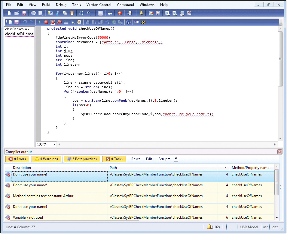
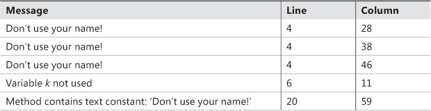
One of the most interesting classes is SysBPCheckMemberFunction, which is called for each piece of X++ code whether it is a class method, form method, macro, or other method. For example, if developers don’t want to include their names in the source code, you can implement a best practice check by creating the following method on the SysBPCheckMemberFunction class:
protected void checkUseOfNames()
{
#Define.MyErrorCode(50000)
container devNames = ['Arthur', 'Lars', 'Michael'];
int i;
int j,k;
int pos;
str line;
int lineLen;
for (i=scanner.lines(); i>0; i--)
{
line = scanner.sourceLine(i);
lineLen = strLen(line);
for (j=conLen(devNames); j>0; j--)
{
pos = strScan(line, conPeek(devNames, j), 1, lineLen);
if (pos)
{
sysBPCheck.addError(#MyErrorCode, i, pos,
"Don't use your name!");
}
}
}
}
To enlist the rule, make sure to call the preceding method from the check method. Compiling this sample code results in the best practice errors shown in Table 2-5.
In an actual implementation, names of developers would probably be read from a file. Ensure that you cache the names to prevent the compiler from going to the disk to read the names for each method being compiled.
![]() Note
Note
The best practice check just shown also identified that the code contained a variable named k that was declared, but never referenced. This is one of the valuable checks that ensures that the code can easily be kept up to date, which helps avoid mistakes. In this case, k was not intended for a specific purpose and can be removed.
Debugger
Like most development environments, MorphX features a debugger. The debugger is a stand-alone application, not part of the AX 2012 shell like the rest of the tools mentioned in this chapter. As a stand-alone application, the debugger allows you to debug X++ in any of the following AX 2012 components:
![]() AX 2012 client
AX 2012 client
![]() AOS
AOS
![]() Business Connector (BC.NET)
Business Connector (BC.NET)
For other debugging scenarios, such as web services, Microsoft SQL Server Reporting Services (SSRS) reports, and Enterprise Portal web client, see Chapter 3, “AX 2012 and .NET.”
Enabling debugging
For the debugger to start, a breakpoint must be hit when X++ code is executed. You set breakpoints by using the X++ code editor in the Development Workspace. The debugger starts automatically when any component hits a breakpoint.
You must enable debugging for each component as follows:
![]() In the Development Workspace, on the Tools menu, click Options > Development > Debug, and then select When Breakpoint in the Debug Mode list.
In the Development Workspace, on the Tools menu, click Options > Development > Debug, and then select When Breakpoint in the Debug Mode list.
![]() From the AOS, open the Microsoft Dynamics AX Server Configuration Utility under Start > Administrative Tools > Microsoft Dynamics AX 2012 Server Configuration. Create a new configuration, if necessary, and then select the check box Enable Breakpoints to debug X++ code running on this server.
From the AOS, open the Microsoft Dynamics AX Server Configuration Utility under Start > Administrative Tools > Microsoft Dynamics AX 2012 Server Configuration. Create a new configuration, if necessary, and then select the check box Enable Breakpoints to debug X++ code running on this server.
![]() For Enterprise Portal code that uses the BCPROXY context to run interpreted X++ code, in the Microsoft Dynamics AX Server Configuration Utility, create a new configuration, if necessary, and select the check box Enable Global Breakpoints.
For Enterprise Portal code that uses the BCPROXY context to run interpreted X++ code, in the Microsoft Dynamics AX Server Configuration Utility, create a new configuration, if necessary, and select the check box Enable Global Breakpoints.
Ensure that you are a member of the local Windows security group named Microsoft Dynamics AX Debugging Users. This is normally ensured by using setup, but if you did not set up AX 2012 by using your current account, you need to do this manually through Edit Local Users And Groups in Windows Control Panel. This is necessary to prohibit unauthorized debugging, which could expose sensitive data, provide a security risk, or impose unplanned service disruptions.
![]() Caution
Caution
It is recommended that you do not enable any of the debugging capabilities in a live environment. If you do, execution will stop when it hits a breakpoint, and the client will stop responding to users. Running the application with debug support enabled also noticeably affects performance.
To set or remove breakpoints, press F9. You can set a breakpoint on any line you want. If you set a breakpoint on a line without an X++ statement, however, the breakpoint will be triggered on the next X++ statement in the method. A breakpoint on the last brace will never be hit.
To enable or disable a breakpoint, press Ctrl+F9. For a list of all breakpoints, press Shift+F9.
Breakpoints are persisted in the SysBreakpoints and SysBreakpointLists database tables. Each developer has his or her own set of breakpoints. This means that your breakpoints are not cleared when you close AX 2012 and that other AX 2012 components can access them and break where you want them to.
Debugger user interface
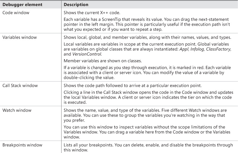
The main window in the debugger initially shows the point in the code where a breakpoint was hit. You can control execution one step at a time while inspecting variables and other aspects of the code. Figure 2-17 shows the debugger opened to a breakpoint with all the windows enabled.
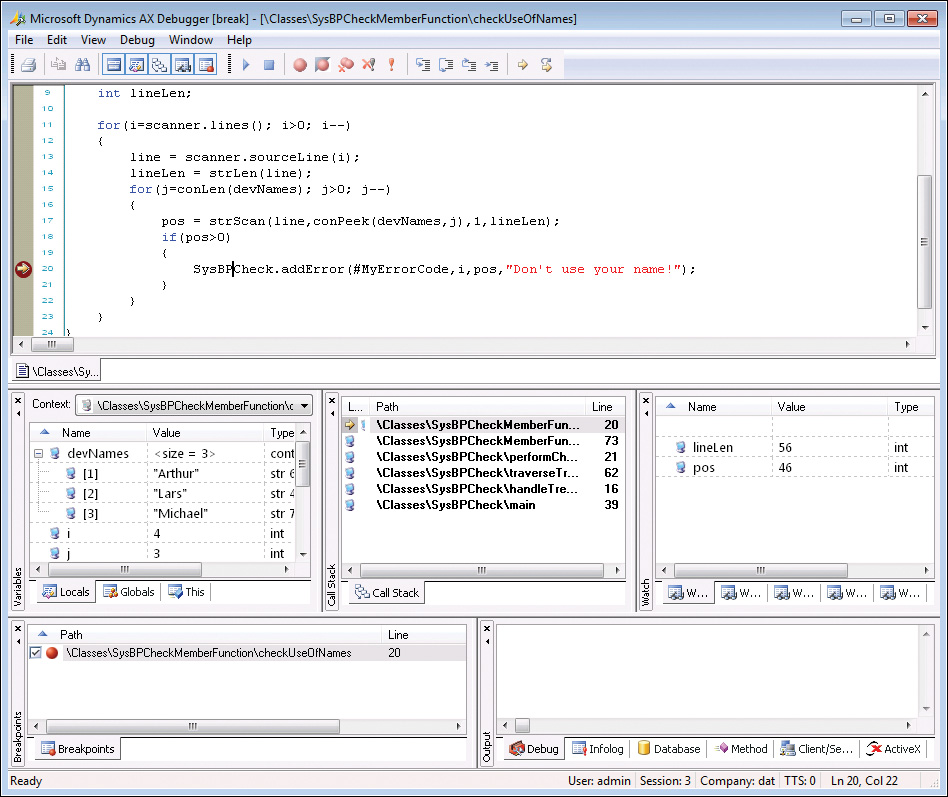
Table 2-6 describes the debugger’s various windows and some of its other features.
![]() Tip
Tip
As a developer, you can provide more information in the value field for your classes than what is provided by default. The defaults for classes are New and Null. You can change the defaults by overriding the toString method. If your class doesn’t explicitly extend the object (the base class of all classes), you must add a new method named toString, returning and taking no parameters, to implement this functionality.
Debugger shortcut keys
Table 2-7 lists the most important shortcut keys available in the debugger.
Reverse Engineering tool
You can generate Visio models from existing metadata. Considering the amount of metadata available in AX 2012 (more than 50,000 elements and more than 18 million lines of text when exported), it’s practically impossible to get a clear view of how the elements relate to each other just by using the AOT. The Reverse Engineering tool is a great aid when you need to visualize metadata.
![]() Note
Note
You must have Visio 2007 or later installed to use the Reverse Engineering tool.
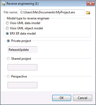
The Reverse Engineering tool can generate a Unified Modeling Language (UML) data model, a UML object model, or an entity relationship data model, including all elements from a private or shared project. To open the tool, in the Projects window, right-click a project or a perspective, and point to Add-Ins > Reverse Engineer. You can also open the tool by selecting Reverse Engineer from the Tools menu. In the dialog box shown in Figure 2-18, you must specify a file name and model type.
When you click OK, the tool uses the metadata for all elements in the project to generate a Visio document that opens automatically. You can drag elements from the Visio Model Explorer onto the drawing surface, which is initially blank. Any relationship between two elements is automatically shown.
UML data model
When generating a UML data model, the Reverse Engineering tool looks for tables in the project. The UML data model contains a class for each table and view in the project and the class’s attributes and associations.
The UML data model also contains referenced tables and all extended data types, base enumerations, and X++ data types. You can include these items in your diagrams without having to run the Reverse Engineering tool again.
Fields in AX 2012 are generated as UML attributes. All attributes are marked as public to reflect the nature of fields in AX 2012. Each attribute also shows the type. The primary key field is underlined. If a field is a part of one or more indexes, the field name is prefixed with the names of the indexes; if the index is unique, the index name is noted in braces.
Relationships in AX 2012 are generated as UML associations. The Aggregation property of the association is set based on two conditions in metadata:
![]() If the relationship is validating (the Validate property is set to Yes), the Aggregation property is set to Shared. This is also known as a UML aggregation, represented by a white diamond.
If the relationship is validating (the Validate property is set to Yes), the Aggregation property is set to Shared. This is also known as a UML aggregation, represented by a white diamond.
![]() If a cascading delete action exists between the two tables, a composite association is added to the model. A cascading delete action ties the lifespan of two or more tables and is represented by a black diamond.
If a cascading delete action exists between the two tables, a composite association is added to the model. A cascading delete action ties the lifespan of two or more tables and is represented by a black diamond.
Figure 2-19 shows a class diagram with the CustTable (customers), InventTable (inventory items), SalesTable (sales order header), and SalesLine (sales order line) tables. To simplify the diagram, some attributes have been removed.
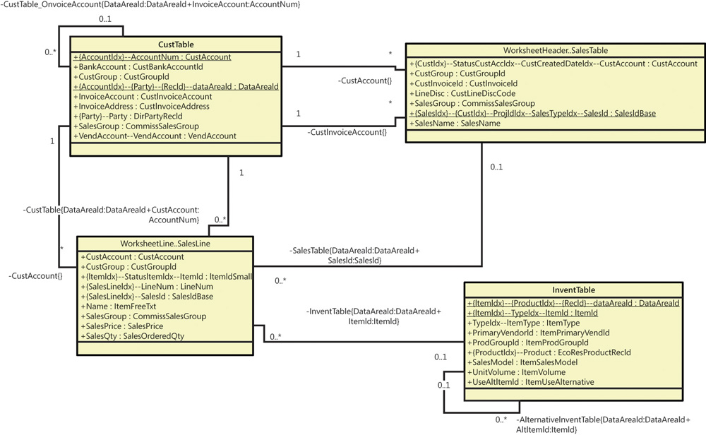
The name of an association endpoint is the name of the relationship. The names and types of all fields in the relationship appear in braces.
UML object model
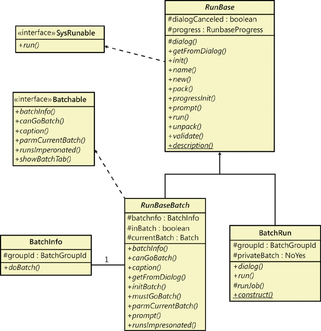
When generating an object model, the Reverse Engineering tool looks for Microsoft Dynamics AX classes, tables, and interfaces in the project. The UML model contains a class for each Microsoft Dynamics AX table and class in the project and an interface for each Microsoft Dynamics AX interface in the project. The UML model also contains attributes and operations, including return types, parameters, and the types of the parameters. Figure 2-20 shows an object model of the most important RunBase and Batch classes and interfaces in Microsoft Dynamics AX. To simplify the view, some attributes and operations have been removed and operation parameters are suppressed.
The UML object model also contains referenced classes, tables, and all extended data types, base enumerations, and X++ data types. You can include these elements in your diagrams without having to run the Reverse Engineering tool again.
Fields and member variables in AX 2012 are generated as UML attributes. All fields are generated as public attributes, whereas member variables are generated as protected attributes. Each attribute also shows the type. Methods are generated as UML operations, including return type, parameters, and the types of the parameters.
The Reverse Engineering tool also picks up any generalizations (classes extending other classes), realizations (classes implementing interfaces), and associations (classes using each other). The associations are limited to references in member variables.
![]() Note
Note
To get the names of operation parameters, you must reverse engineer in debug mode. The names are read from metadata only and are placed into the stack when in debug mode. To enable debug mode, on the Development tab of the Options form, select When Breakpoint in the Debug Mode list.
For more information about the elements in a UML diagram, see “UML Class Diagrams: Reference” at http://msdn.microsoft.com/en-us/library/dd409437.aspx.
Entity relationship data model
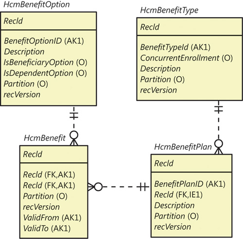
When generating an entity relationship data model, the Reverse Engineering tool looks for tables and views in the project. The entity relationship model contains an entity type for each AOT table in the project and attributes for the fields in each table. Figure 2-21 shows an entity relationship diagram (ERD) for the tables HcmBenefit (Benefit), HcmBenefitOption (Benefit option), HcmBenefitType (Benefit type), and HcmBenefitPlan (Benefit plan).
![]() Note
Note
For AX 2012 R2, Microsoft has introduced a website that hosts ERDs for the core tables in AX 2012 R2 application modules. You can use the site to quickly get detailed information about a large number of tables. To access the site, go to http://www.microsoft.com/dynamics/ax/erd/ax2012r2/Default.htm.
Fields in AX 2012 are generated as entity relationship columns. Columns can be foreign key (FK), alternate key (AK), inversion entry (IE), and optional (O). A foreign key column is used to identify a record in another table, an alternate key uniquely identifies a record in the current table, an inversion entry identifies zero or more records in the current table (these are typical of the fields in nonunique indexes), and optional columns don’t require a value.
Relationships in AX 2012 are generated as entity relationships. The EntityRelationshipRole property of the relationship is used as the foreign key role name of the relation in the entity relationship data model.
![]() Note
Note
The Reverse Engineering tool produces an ERX file. To work with the generated file in Visio, do the following: In Visio, create a new database model diagram, and then on the Database tab, point to Import > Import ERwin ERX File. Afterward, you can drag relevant tables from the Tables And Views pane (available from the Database tab) to the diagram canvas.
Table Browser tool
The Table Browser tool is a small, helpful tool that can be used in numerous scenarios. You can browse and maintain the records in a table without having to build a user interface. This tool is useful when you’re debugging, validating data models, and modifying or cleaning up data, to name just a few uses.
To access the Table Browser tool, right-click any of the following types of items in the AOT, and then point to Add-Ins > Table Browser:
![]() Tables
Tables
![]() Tables listed as data sources in forms, queries, and data sets
Tables listed as data sources in forms, queries, and data sets
![]() System tables listed in the AOT under System DocumentationTables
System tables listed in the AOT under System DocumentationTables
![]() Note
Note
The Table Browser tool is implemented in X++. You can find it in the AOT under the name SysTableBrowser. It is a good example of how to bind the data source to a table at run time.
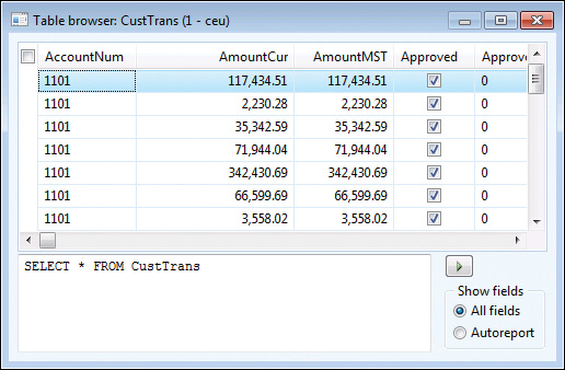
Figure 2-22 shows the Table Browser tool when it is started from the CustTrans table. In addition to the querying, sorting, and filtering capabilities provided by the grid control, you can type an SQ SELECT statement directly into the form by using X++ SELECT statement syntax and see a visual display of the result set. This tool is a great way to test complex SELECT statements. It fully supports grouping, sorting, aggregation, and field lists.
You can also choose to see only the fields from the auto-report field group. These fields are printed in a report when the user clicks Print in a form with this table as a data source. Typically, these fields hold the most interesting information. This option can make it easier to find the values you’re looking for in tables with many fields.
![]() Note
Note
The Table Browser tool is just a standard form that uses IntelliMorph. It can’t display fields for which the visible property is set to No or fields that the current user doesn’t have access to.
Find tool
Search is everything, and the size of AX 2012 applications calls for a powerful and effective search tool.
![]() Tip
Tip
You can use the Find tool to search for an example of how to use an API. Real examples can complement the examples found in the documentation.
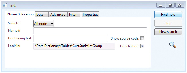
You can start the Find tool, shown in Figure 2-23, from any node in the AOT by pressing Ctrl+F or by clicking Find on the context menu. The Find tool supports multiple selections in the AOT.
On the Name & Location tab, you define what you’re searching for and where to look:
![]() In the Search list, the options are Methods and All Nodes. If you choose All Nodes, the Properties tab appears.
In the Search list, the options are Methods and All Nodes. If you choose All Nodes, the Properties tab appears.
![]() The Named box limits the search to nodes with the name you specify.
The Named box limits the search to nodes with the name you specify.
![]() The Containing Text box specifies the text to look for in the method, expressed as a regular expression.
The Containing Text box specifies the text to look for in the method, expressed as a regular expression.
![]() If you select the Show Source Code check box, results include a snippet of source code containing the match, making it easier to browse the results.
If you select the Show Source Code check box, results include a snippet of source code containing the match, making it easier to browse the results.
By default, the Find tool searches the node (and its subnodes) selected in the AOT. If you change focus in the AOT while the Find tool is open, the Look In value is updated. This is quite useful if you want to search several nodes by using the same criterion. You can disable this behavior by clearing the Use Selection check box.
On the Date tab, you specify additional ranges for your search, such as Modified Date and Modified By.
On the Advanced tab, you can specify more advanced settings for your search, such as the layer to search, the size range of elements, the type of element, and the tier on which the element is set to run.
On the Filter tab, shown in Figure 2-24, you can write a more complex query by using X++ and type libraries. The code in the Source text box is the body of a method with the following profile:
boolean FilterMethod(str _treeNodeName,
str _treeNodeSource,
XRefPath _path,
ClassRunMode _runMode)
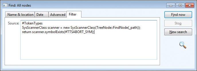
The example in Figure 2-24 uses the class SysScannerClass to find any occurrence of the ttsAbort X++ keyword. The scanner is primarily used to pass tokens into the parser during compilation. Here, however, it detects the use of a particular keyword. This tool is more accurate (though slower) than using a regular expression because X++ comments don’t produce tokens.
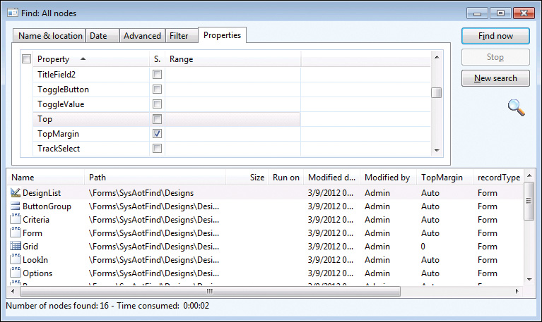
The Properties tab appears when All Nodes is selected in the Search list. You can specify a search range for any property. Leaving the range blank for a property is a powerful setting when you want to inspect properties: it matches all nodes, and the property value is added as a column in the results, as shown in Figure 2-25. The search begins when you click Find Now. The results appear at the bottom of the dialog box as they are found.
Double-clicking any line in the result set opens the X++ code editor and sets the focus on the code example that matches. When you right-click the lines in the result set, a context menu containing the Add-Ins menu opens.
Compare tool
Several versions of the same element typically exist. These versions might emanate from various layers or revisions in version control, or they could be modified versions that exist in memory. AX 2012 has a built-in Compare tool that highlights any differences between two versions of an element.
The comparison shows changes to elements, which can be modified in three ways:
![]() A metadata property can be changed.
A metadata property can be changed.
![]() X++ code can be changed.
X++ code can be changed.
![]() The order of subnodes can be changed, such as the order of tabs on a form.
The order of subnodes can be changed, such as the order of tabs on a form.
Starting the Compare tool
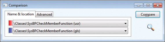
To open the Compare tool, right-click an element, and then click Compare. A dialog box opens where you can select the versions of the element you want to compare, as shown in Figure 2-26.
The versions to choose from come from many sources. The following is a list of all possible types of versions:
![]() Standard layered version types These include SYS, SYP, GLS, GLP, FPK, FPP, SLN, SLP, ISV, ISP, VAR, VAP, CUS, CUP, USR, and USP.
Standard layered version types These include SYS, SYP, GLS, GLP, FPK, FPP, SLN, SLP, ISV, ISP, VAR, VAP, CUS, CUP, USR, and USP.
![]() Old layered version types (old SYS, old SYP, and so on) If a baseline model store is present, elements from the files are available here. This allows you to compare an older version of an element with its latest version. For more information about layers and the baseline model store, see Chapter 21, “Application models.”
Old layered version types (old SYS, old SYP, and so on) If a baseline model store is present, elements from the files are available here. This allows you to compare an older version of an element with its latest version. For more information about layers and the baseline model store, see Chapter 21, “Application models.”
![]() Version control revisions (Version 1, Version 2, and so on) You can retrieve any revision of an element from the version control system individually and use it for comparison. The version control system is explained later in this chapter.
Version control revisions (Version 1, Version 2, and so on) You can retrieve any revision of an element from the version control system individually and use it for comparison. The version control system is explained later in this chapter.
![]() Best practice washed version (Washed) A few simple best practice issues can be resolved automatically by a best practice “wash.” Selecting the washed version shows you how your implementation differs from best practices. To get the full benefit of this, select the Case Sensitive check box on the Advanced tab.
Best practice washed version (Washed) A few simple best practice issues can be resolved automatically by a best practice “wash.” Selecting the washed version shows you how your implementation differs from best practices. To get the full benefit of this, select the Case Sensitive check box on the Advanced tab.
![]() Export/import file (XPO) Before you import elements, you can compare them with existing elements (which will be overwritten during import). You can use the Compare tool during the import process (Command > Import) by selecting the Show Details check box in the Import dialog box and right-clicking any elements that appear in bold. Objects in bold already exist in the application.
Export/import file (XPO) Before you import elements, you can compare them with existing elements (which will be overwritten during import). You can use the Compare tool during the import process (Command > Import) by selecting the Show Details check box in the Import dialog box and right-clicking any elements that appear in bold. Objects in bold already exist in the application.
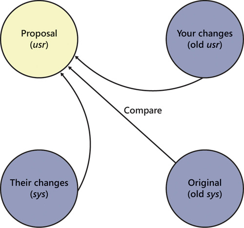
![]() Upgraded version (Upgraded) MorphX can automatically create a proposal for how a class should be upgraded. The requirement for upgrading a class arises during a version upgrade. The Create Upgrade Project step in the Upgrade Checklist automatically detects customized classes that conflict with new versions of the classes. A class is conflicting if you’ve changed the original version of the class, and the publisher of the class has also changed the original version. MorphX constructs the proposal by merging your changes with the publisher’s changes to the class. MorphX requires access to all three versions of the class—the original version in the baseline model store, a version with your changes in the current layer in the baseline model store, and a version with the publisher’s changes in the same layer as the original. The installation program ensures that the right versions are available in the right places during an upgrade. Conflict resolution is shown in Figure 2-27.
Upgraded version (Upgraded) MorphX can automatically create a proposal for how a class should be upgraded. The requirement for upgrading a class arises during a version upgrade. The Create Upgrade Project step in the Upgrade Checklist automatically detects customized classes that conflict with new versions of the classes. A class is conflicting if you’ve changed the original version of the class, and the publisher of the class has also changed the original version. MorphX constructs the proposal by merging your changes with the publisher’s changes to the class. MorphX requires access to all three versions of the class—the original version in the baseline model store, a version with your changes in the current layer in the baseline model store, and a version with the publisher’s changes in the same layer as the original. The installation program ensures that the right versions are available in the right places during an upgrade. Conflict resolution is shown in Figure 2-27.
![]() Note
Note
You can also compare two different elements. To do this, select two elements in the AOT, right-click, point to Add-Ins, and then click Compare.
Figure 2-28 shows the Advanced tab, on which you can specify comparison options.
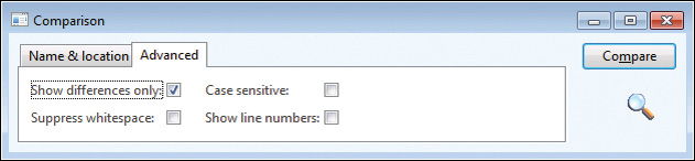
The following list describes the comparison options shown in Figure 2-28:
![]() Show Differences Only All equal nodes are suppressed from the view, making it easier to find the changed nodes. This option is selected by default.
Show Differences Only All equal nodes are suppressed from the view, making it easier to find the changed nodes. This option is selected by default.
![]() Suppress Whitespace White space, such as spaces and tabs, is suppressed into a single space during the comparison. The Compare tool can ignore the amount of white space, just as the compiler does. This option is selected by default.
Suppress Whitespace White space, such as spaces and tabs, is suppressed into a single space during the comparison. The Compare tool can ignore the amount of white space, just as the compiler does. This option is selected by default.
![]() Case Sensitive Because X++ is not case sensitive, the Compare tool is also not case sensitive by default. In certain scenarios, case sensitivity is required and must be enabled, such as when you’re using the best practice wash feature mentioned earlier in this section. This option is cleared by default.
Case Sensitive Because X++ is not case sensitive, the Compare tool is also not case sensitive by default. In certain scenarios, case sensitivity is required and must be enabled, such as when you’re using the best practice wash feature mentioned earlier in this section. This option is cleared by default.
![]() Show Line Numbers The Compare tool can add line numbers to all X++ code that is displayed. This option is cleared by default but can be useful during an upgrade of large chunks of code.
Show Line Numbers The Compare tool can add line numbers to all X++ code that is displayed. This option is cleared by default but can be useful during an upgrade of large chunks of code.
Using the Compare tool
After you choose elements and set parameters, start the comparison by clicking Compare. Results are displayed in a three-pane dialog box, as shown in Figure 2-29. The top pane contains the elements and options that you selected, the left pane displays a tree structure resembling the AOT, and the right pane shows details that correspond to the item selected in the tree.
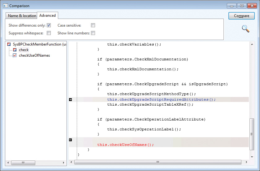
Color-coded icons in the tree structure indicate how each node has changed. A red or blue check mark indicates that the node exists only in a particular version. Red corresponds to the SYS layer, and blue corresponds to the old SYS layer. A gray check mark indicates that the nodes are identical but one or more subnodes are different. A not-equal-to sign (≠) on a red and blue background indicates that the nodes are different in the two versions.
Each node in the tree view has a context menu that provides access to the Add-Ins submenu and the Open New Window option. The Open New Window option provides an AOT view of any element, including elements in old layers.
Details about the differences are shown in the right pane. Color coding is also used in this pane to highlight differences the same way that it is in the tree structure. If an element is editable, small action icons appear. These icons allow you to make changes to code, metadata, and nodes, which can save you time when performing an upgrade. A right or left arrow removes or adds the difference, and a bent arrow moves the difference to another position. These arrows always come in pairs, so you can see where the difference is moved to and from. If a version control system is in use, an element is editable if it is from the current layer and is checked out.
Compare APIs
Although AX 2012 provides comparison functionality for development purposes only, you can reuse the comparison functionality for other tasks. You can use the available APIs to compare and present differences in the tree structure or text representation of any type of entity.
The Tutorial_CompareContextProvider class shows how simple it is to compare business data by using these APIs and present it by using the Compare tool. The tutorial consists of two parts:
![]() Tutorial_Comparable This class implements the SysComparable interface. Basically, it creates a text representation of a customer.
Tutorial_Comparable This class implements the SysComparable interface. Basically, it creates a text representation of a customer.
![]() Tutorial_CompareContextProvider This class implements the SysCompareContextProvider interface. It provides the context for comparison. For example, it creates a Tutorial_Comparable object for each customer, sets the default comparison options, and handles context menus.
Tutorial_CompareContextProvider This class implements the SysCompareContextProvider interface. It provides the context for comparison. For example, it creates a Tutorial_Comparable object for each customer, sets the default comparison options, and handles context menus.
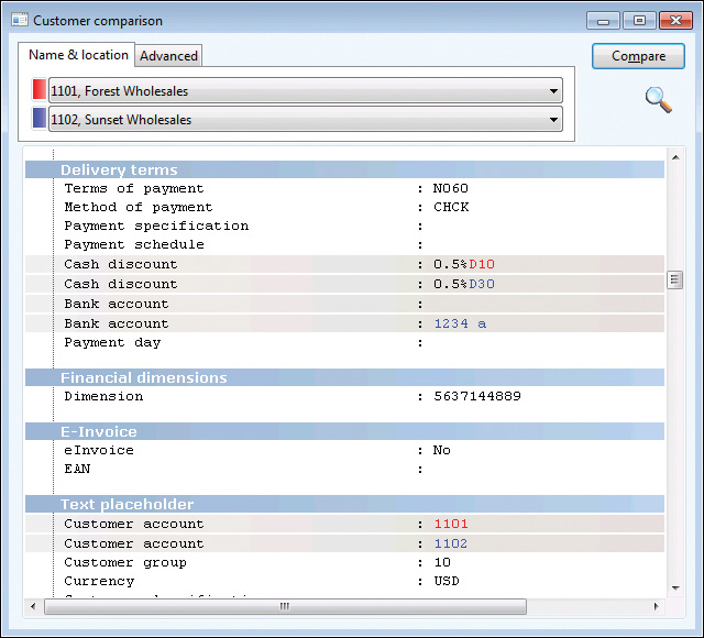
Figure 2-30 shows a comparison of two customers, the result of running the tutorial.
You can also use the line-by-line comparison functionality directly in X++. The static run method on the SysCompareText class, shown in the following code, takes two strings as parameters and returns a container that highlights differences in the two strings. You can also use a set of optional parameters to control the comparison.
public static container run(str _t1,
str _t2,
boolean _caseSensitive = false,
boolean _suppressWhiteSpace = true,
boolean _lineNumbers = false,
boolean _singleLine = false,
boolean _alternateLines = false)
Cross-Reference tool
The concept of cross-references in AX 2012 is simple. If an element uses another element, the reference is recorded. With cross-references, you can determine which elements a particular element uses and which elements other elements are using. AX 2012 provides the Cross-Reference tool for accessing and managing cross-reference information.
Here are a couple of typical scenarios for using the Cross-Reference tool:
![]() You want to find usage examples. If the product documentation doesn’t help, you can use the Cross-Reference tool to find real implementation examples.
You want to find usage examples. If the product documentation doesn’t help, you can use the Cross-Reference tool to find real implementation examples.
![]() You need to perform an impact analysis. If you’re changing an element, you need to know which other elements are affected by your change.
You need to perform an impact analysis. If you’re changing an element, you need to know which other elements are affected by your change.
You must update the Cross-Reference tool regularly to ensure accuracy. The update typically takes several hours. The footprint in a database is about 1.5 gigabytes (GB) for a standard application.
To update the Cross-Reference tool, on the Tools menu, point to > Cross-Reference > Periodic > Update. Updating the Cross-Reference tool also compiles the entire AOT because the compiler emits cross-reference information.
![]() Tip
Tip
Keeping the Cross-Reference tool up to date is important if you want its information to be reliable. If you work in a shared development environment, you share cross-reference information with your team members. Updating the Cross-Reference tool nightly is a good approach for a shared environment. If you work in a local development environment, you can keep the Cross-Reference tool up to date by enabling cross-referencing when compiling. This option slows down compilation, however. Another option is to update cross-references manually for the elements in a project. To do so, right-click the project and point to Add-Ins > Cross-Reference > Update.
In addition to the main cross-reference information, two smaller cross-reference subsystems exist:
![]() Data model Stores information about relationships between tables. It is primarily used by the query form and the Reverse Engineering tool.
Data model Stores information about relationships between tables. It is primarily used by the query form and the Reverse Engineering tool.
![]() Type hierarchy Stores information about class and data type inheritance.
Type hierarchy Stores information about class and data type inheritance.
For more information about these subsystems and the tools that rely on them, see the AX 2012 SDK (http://msdn.microsoft.com/en-us/library/aa496079.aspx).
The information that the Cross-Reference tool collects is quite comprehensive. You can find a complete list of cross-referenced elements by opening the AOT, expanding the System Documentation node, and clicking Enums and then xRefKind. When the Cross-Reference tool is updating, it scans all metadata and X++ code for references to elements of the kinds listed in the xRefKind subnode.
![]() Tip
Tip
It’s a good idea to use intrinsic functions when referring to elements in X++ code. An intrinsic function can evaluate to either an element name or an ID. The intrinsic functions are named <Element type>Str or <Element type>Num, respectively. Using intrinsic functions provides two benefits: you have compile-time verification that the element you reference actually exists, and the reference is picked up by the Cross-Reference tool. Also, there is no run-time overhead. Here is an example:
// Prints ID of MyClass, such as 50001
print classNum(myClass);
// Prints "MyClass"
print classStr(myClass);
// No compile check or cross-reference
print "MyClass";
For more information about intrinsic functions, see Chapter 20, “Reflection.”
To access usage information, right-click any element in the AOT and point to Add-Ins > Cross-Reference > Used By. If the option isn’t available, either the element isn’t used or the cross-reference hasn’t been updated.
Figure 2-31 shows where the prompt method is used on the RunBaseBatch class.
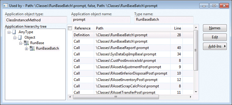
When you view cross-references for a class method, the Application hierarchy tree is visible, so that you can see whether the same method is used on a parent or subclass. For types that don’t support inheritance, the Application hierarchy tree is hidden.
Version control
The Version Control tool in MorphX makes it possible to use a version control system, such as Microsoft Visual SourceSafe or Visual Studio Team Foundation Server (TFS), to keep track of changes to elements in the AOT. The tool is accessible from several places: from the Version Control menu in the Development Workspace, from toolbars in the AOT and the X++ code editor, and from the context menu on elements in the AOT.
Using a version control system offers several benefits:
![]() Revision history of all elements All changes are captured, along with a description of the change, making it possible to consult the change history and retrieve old versions of an element.
Revision history of all elements All changes are captured, along with a description of the change, making it possible to consult the change history and retrieve old versions of an element.
![]() Code quality enforcement The implementation of version control in AX 2012 enables a fully configurable quality standard for all check-ins. With the quality standard, all changes are verified according to coding practices. If a change doesn’t meet the criteria, it is rejected.
Code quality enforcement The implementation of version control in AX 2012 enables a fully configurable quality standard for all check-ins. With the quality standard, all changes are verified according to coding practices. If a change doesn’t meet the criteria, it is rejected.
![]() Isolated development Each developer can have a local installation and make all modifications locally. When modifications are ready, they can be checked in and made available to consumers of the build. A developer can rewrite fundamental areas of the system without causing instability issues for others. Developers are also unaffected by any downtime of a centralized development server.
Isolated development Each developer can have a local installation and make all modifications locally. When modifications are ready, they can be checked in and made available to consumers of the build. A developer can rewrite fundamental areas of the system without causing instability issues for others. Developers are also unaffected by any downtime of a centralized development server.
Even though using a version control system is optional, it is strongly recommended that you consider one for any development project. AX 2012 supports three version control systems: Visual SourceSafe 6.0 and TFS, which are designed for large development projects, and MorphX VCS. MorphX Version Control System (VCS) is designed for smaller development projects that previously couldn’t justify the additional overhead that using a version control system server adds to the process. Table 2-8 shows a side-by-side comparison of the version control system options.
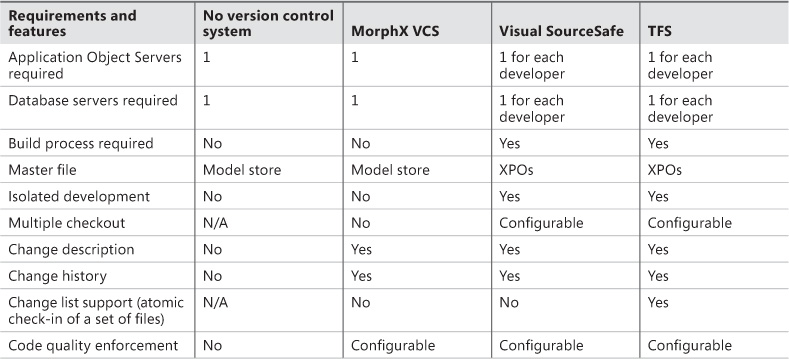
The elements persisted on the version control server are file representations of the elements in the AOT. The file format used is the standard Microsoft Dynamics AX export format (.xpo). Each .xpo file contains only one root element.
There are no additional infrastructure requirements when you use MorphX VCS, which makes it a perfect fit for partners running many parallel projects. In such setups, each developer often works simultaneously on several projects, toggling between projects and returning to past projects. In these situations, the benefits of having a change history are enormous. With just a few clicks, you can enable MorphX VCS to persist the changes in the business database. Although MorphX VCS provides many of the same capabilities as a version control server, it has some limitations. For example, MorphX VCS does not provide any tools for maintenance, such as making backups, archiving, or labeling.
In contrast, Visual SourceSafe and TFS are designed for large projects in which many developers work together on the same project for an extended period of time (for example, an independent software vendor building a vertical solution).
Figure 2-32 shows a typical deployment using Visual SourceSafe or TFS, in which each developer locally hosts the AOS and the database. Each developer also needs a copy of all .xpo files. When a developer communicates with the version control server, the .xpo files are transmitted.
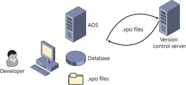
In earlier versions of Microsoft Dynamics AX, a Team Server was required to assign unique IDs as elements were created. AX 2012 uses a new ID allocation scheme, which eliminates the need for the Team Server. For more information about element IDs, see Chapter 21.
Element life cycle
Figure 2-33 shows the element life cycle in a version control system. When an element is in a state marked with a lighter shade, it can be edited; otherwise, it is read-only.
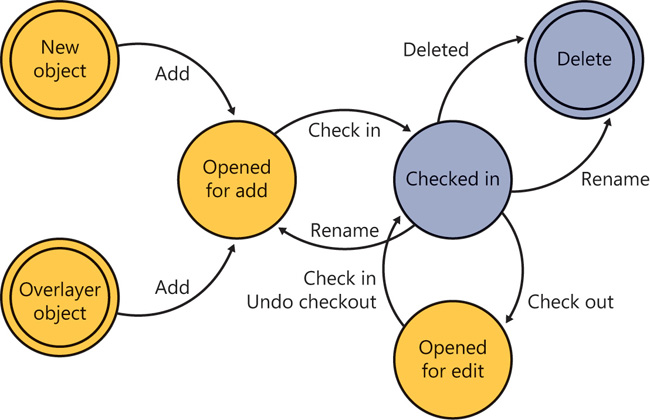
You can create an element in two ways:
![]() Create a new element.
Create a new element.
![]() Customize an existing element, resulting in an overlayered version of the element. Because elements are stored for each layer in the version control system, customizing an element effectively creates a new element.
Customize an existing element, resulting in an overlayered version of the element. Because elements are stored for each layer in the version control system, customizing an element effectively creates a new element.
After you create an element, you must add it to the version control system. First, give it a proper name in accordance with naming conventions, and then click Add To Version Control on the context menu. After you create the element, you must check it in.
An element that is checked in can be renamed. Renaming an element deletes the element with the old name and adds an element with the new name.
Quality checks
Before the version control system accepts a check-in, it might subject the elements to quality checks. You define what is accepted in a check-in when you set up the version control system. The following checks are supported:
![]() Compiler errors
Compiler errors
![]() Compiler warnings
Compiler warnings
![]() Compiler tasks
Compiler tasks
![]() Best practice errors
Best practice errors
When a check is enabled, it is carried out when you do a check-in. If the check fails, the check-in stops. You must address the issue and restart the check-in.
Source code casing
You can set the Source Code Titlecase Update tool, available on the Add-Ins submenu, to execute automatically before elements are checked in to ensure uniform casing in variable and parameter declarations and references. You can specify this parameter when setting up the version control system by selecting the Run Title Case Update check box.
Common version control tasks
Table 2-9 describes some of the tasks that are typically performed with a version control system. Later sections describe additional tasks that you can perform when using version control with AX 2012.
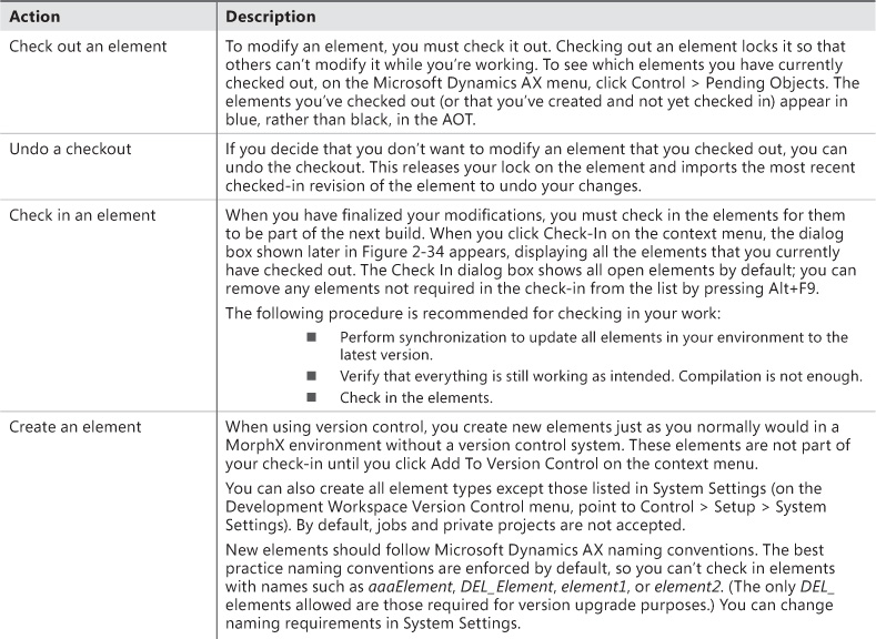
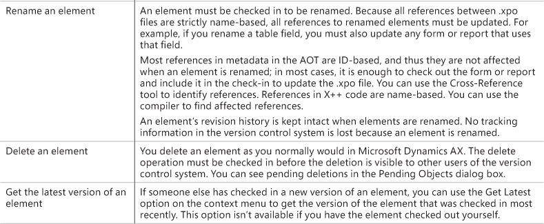
Working with labels
Working with labels is similar to working with elements. To change, delete, or add a label, you must check out the label file containing the label. You can check out the label file from the Label editor dialog box.
The main difference between checking out elements and checking out label files is that simultaneous checkouts are allowed for label files. This means that others can change labels while you have a label file checked out.
Figure 2-34 shows the Check In dialog box.
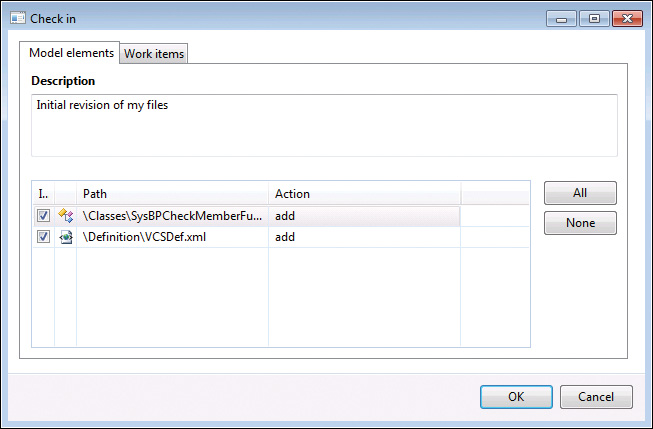
If you create a new label when using version control, a temporary label ID is assigned (for example, @$AA0007 as opposed to @USR1921). When you check in a label file, your changes are automatically merged into the latest version of the file and the temporary label IDs are updated. All references in the code are automatically updated to the newly assigned label IDs. Temporary IDs eliminate the need for a central Team Server, which was required for AX 2009, because IDs no longer have to be assigned when the labels are created. If you modify or delete a label that another person has also modified or deleted, your conflicting changes are abandoned. Such lost changes are shown in the Infolog after the check-in completes.
Synchronizing elements
Synchronization makes it possible for you to get the latest version of all elements. This step is required before you can check in any elements. You can initiate synchronization from the Development Workspace. On the Version Control menu, point to Periodic > Synchronize.
Synchronization is divided into three operations that happen automatically in the following sequence:
1. The latest files are copied from the version control server to the local disk.
2. The files are imported into the AOT.
3. The imported files are compiled.
Use synchronization to make sure your system is up to date. Synchronization won’t affect any new elements that you have created or any elements that you have checked out.
Figure 2-35 shows the Synchronization dialog box.
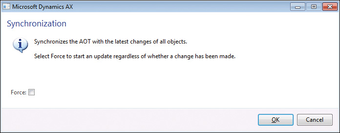
Selecting the Force check box gets the latest version of all files, even if they haven’t changed, and then imports every file.
When using Visual SourceSafe, you can also synchronize to a label defined in Visual SourceSafe. This way, you can easily synchronize to a specific build or version number.
Synchronization is not available with MorphX VCS.
Viewing the synchronization log
The way that you keep track of versions on the client depends on your version control system. Visual SourceSafe requires that AX 2012 keep track of itself. When you synchronize the latest version, it is copied to the local repository folder from the version control system. Each file must be imported into AX 2012 to be reflected in the AOT. To minimize the risk of partial synchronization, a log entry is created for each file. When all files are copied locally, the log is processed, and the files are automatically imported into AX 2012.
When synchronization fails, the import operation is usually the cause of the problem. Synchronization failure leaves your system in a partially synchronized state. To complete the synchronization, restart AX 2012 and restart the import. You use the synchronization log to restart the import, and you access it from the Development Workspace menu at Version Control > Inquiries > Synchronization log.
The Synchronization Log dialog box, shown in Figure 2-36, displays each batch of files, and you can restart the import operation by clicking Process. If the Completed check box is not selected, the import has failed and should be restarted.
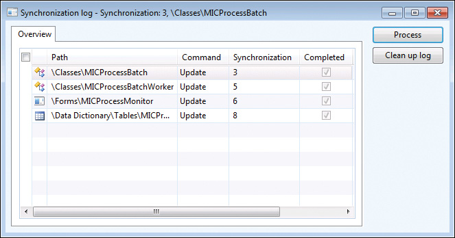
The Synchronization log is not available with MorphX VCS.
Showing the history of an element
One of the biggest advantages of version control is the ability to track changes to elements. Selecting History on an element’s context menu displays a list of all changes to an element, as shown in Figure 2-37.
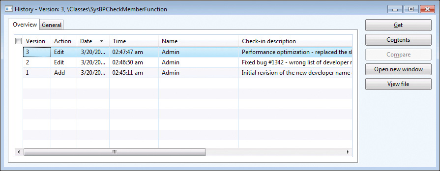
For each revision, this dialog box shows the version number, the action performed, the time the action was performed, and who performed the action. You can also see the change number and the change description.
A set of buttons in the History dialog box allows further investigation of each version. Clicking Contents opens a form that shows other elements included in the same change. Clicking Compare opens the Compare dialog box, where you can do a line-by-line comparison of two versions of the element. The Open New Window button opens an AOT window that shows the selected version of the element, which is useful for investigating properties because you can use the standard MorphX toolbox. Clicking View File opens the .xpo file for the selected version in Notepad.
Comparing revisions
Comparison is the key to harvesting the benefits of a version control system. You can start a comparison from several places, including from the context menu of an element, by pointing to Compare. Figure 2-38 shows the Comparison dialog box, where two revisions of the form CustTable are selected.
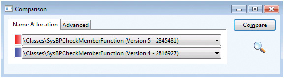
The Compare dialog box contains a list of all checked-in versions, in addition to the element versions available in other layers that are installed.
Viewing pending elements
When you’re working on a project, it’s easy to lose track of which elements you’ve opened for editing. The Pending Objects dialog box, shown in Figure 2-39, lists the elements that are currently checked out in the version control system. Notice the column containing the action performed on the element. Deleted elements are available only in this dialog box; they are no longer shown in the AOT.
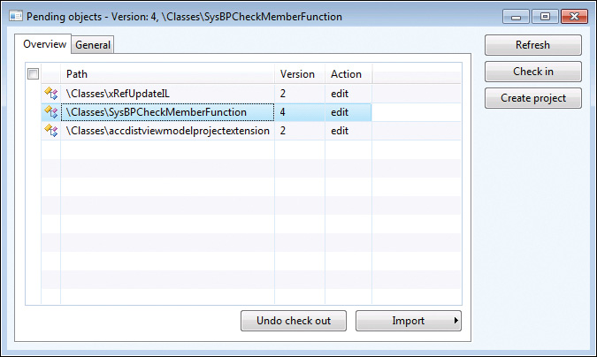
You can access the Pending Objects dialog box from the Development Workspace menu: Version Control > Pending Objects.
Creating a build
Because the version control system contains .xpo files and not a model file, a build process is required to generate the model file from the .xpo files. The following procedure provides a high-level overview of the build process:
1. Use the CombineXPOs command-line utility to combine all .xpo files into one. This step makes the .xpo file consumable by AX 2012. AX 2012 requires all referenced elements to be present in the .xpo file or to already exist in the AOT to maintain the references during import.
2. Import the new .xpo file by using the command-line parameter -AOTIMPORTFILE=<FileName.xpo>-MODEL=<Model Name> to Ax32.exe. This step imports the .xpo file and compiles everything. After this step is complete, the new model is ready in the model store.
3. Export the model to a file by using the axutil command-line utility: axutil export/model:<model name> /file:<model file name>.
4. Follow these steps for each layer and each model that you build.
The build process doesn’t apply to MorphX VCS.
Integrating AX 2012 with other version control systems
The implementation of the version control system in AX 2012 is fully pluggable. This means that any version control system can be integrated with AX 2012.
Integrating with another version control system requires a new class implementing the SysVersionControlFileBasedBackEnd interface. It is the implementation’s responsibility to provide the communication with the version control system server being used.