
In this section, we will simulate the usage of a relay device with an LED. Once we understand the basics of interfacing a relay device, we will move on to using an actual AC bulb with a relay.
For building the simulated prototype the following parts will be required:
- Arduino Uno R3
- USB connector
- Two pieces 1.5V AA batteries + holder case
- One sound detector sensor module
- One 5V 10A AC power relay
- One red LED
- One 100 Ohms resistor
- Jumper wires as required
Before moving on, since we will also use a sound detector module with our prototype, let us quickly take a look at the basic pin out of a typical sound detector device:

As we can see in the preceding figure, a typical sound detector module has the following main parts:
- Microphone: The microphone is used to receive ambient sound waves.
- Potentiometer: The potentiometer allows us to manually adjust the sound level threshold at which the sound detector module will detect ambient sound. Depending upon the sound detector module, you will have to perform some trial and error for finding out the right position at which the potentiometer must be kept at, for meeting your project requirements. For the sketch in this chapter, there is no need to manually modify the position of the potentiometer.
Once all the components are available, follow the breadboard diagram shown to build the circuit:
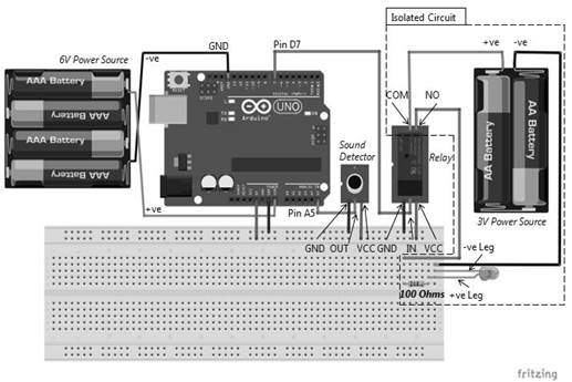
As shown in the preceding figure, the sound detector to Arduino Uno connections are tabulated as follows:
|
Arduino Uno pin |
Sound sensor pin |
|
Analog I/O pin A5 |
OUT |
|
5V |
VCC |
|
GND |
GND |
As shown in the preceding figure, the relay to Arduino Uno connections are tabulated as follows:
|
Arduino Uno pin |
Relay Port/Jack/Pin |
|
Digital I/O pin 7 |
IN |
|
5V |
VCC |
|
GND |
GND |
The relay to DC power and LED connections are tabulated as follows:
|
Relay port |
DC Power/Device |
|
COM |
Positive terminal |
|
NO |
To LED (via bread board) |
The positive terminal of the power supply should be connected to the COM terminal of the relay device. The negative terminal of the power supply should be connected to the other end of the LED. Once everything is in place, load the sketch mentioned in a later part of this chapter and see how the sound detector triggers the switching of the LED light. All you need to do is to snap your fingers in front of the sound detector.