
The datasheet is a fundamental piece of documentation that describes an electronic component in great detail. These documents are usually created and published by the device manufacturers and are freely available online. You may search for a specific device datasheet online and download the document.
Typically, a sensor device datasheet includes detailed descriptions, including a circuit diagram describing how to interface the sensor with a microcontroller. The datasheet is also very useful in finding out the operating conditions of a device.
Taking the example of the DHT11 sensor datasheet, it can be found by simply searching the phrase DHT11 datasheet in a search engine of your choice and then downloading the PDF file.
It is common to find this datasheet on several websites. The datasheet demonstrated in this book is from Micropik.com. At the time of writing this book the datasheet was available at the following link:
http://www.micropik.com/PDF/dht11.pdf.
Determining how to connect the sensor
The next step is to study the datasheet carefully and locate the page in the datasheet PDF file, where there is either a circuit diagram or an explanation of how to connect the sensor chip to a microcontroller. Once the connection details are found, it becomes fairly easy to connect the sensor with the Arduino board.
In the case of DHT11's datasheet, the following connection diagram can be found. Let us look at this connection diagram and understand how to use the information for connecting the DHT11 temperature sensor to Arduino Uno (the MCU or microcontroller, in our case):
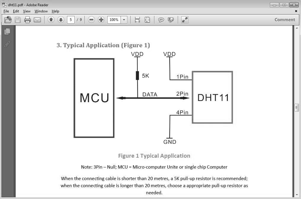
As shown in the preceding figure, the DHT11 sensor has four pins. It is important to notice that pin number 3 is missing in the preceding diagram and that there is a line that says - Note: 3Pin - Null. This means that the sensor module's pin number 3 is not required to be used for the connection.
After reading through the beginning of the datasheet, it will become clear that the DHT11 sensor module gives digital output. Hence, the output (pin 2) of the sensor should be connected to any digital pin of the Arduino board.
Based on the preceding diagram, the connection of each DHT11 pin to Arduino Uno is mapped in the following table:
|
DHT11 pin |
Arduino Uno pin |
Connection remarks |
|
Pin 1 |
5V (VDD indicates the 5V pin on Arduino) |
Connect directly to the 5V pin. |
|
Pin 2 |
Any digital pin use digital pin 2 in this example (DATA indicates signals between the sensor and microcontroller) |
Connect directly to digital pin 2. Also, place a 5K resistor between DHT11 pin 2 and Arduino's 5V pin. |
|
Pin 3 |
N/A |
This pin is marked as null which means that pin number 3 is unused and therefore it will not be connected to anything. |
|
Pin 4 |
GND |
Connect directly to any GND pin. |
Connecting the 5K resistor adds a slight twist to setting up the DHT11 sensor with Arduino. Note how the 5K resistor connects pin1 and pin 2. The practical implementation of the preceding circuit diagram with Arduino is shown in the following diagram.
At this point, you must try to look hard and close at the connection between the schematic diagram in the datasheet and the breadboard circuit setup shown next and try to internalize how the indicative circuit diagram in the datasheet was translated into a practical setup shown using the breadboard:

Notice how the 5K Ohms resistor is connected between pin 1 and pin 2. Now, look back at the datasheet diagram and try to understand why this was done.
After you have understood the circuit, the next step would be to look at the sensor-specific Arduino library. We will use the Arduino library for the sensor to read the temperature data from the sensor.