
It is very common to find buttons on every device all around us, be it a simple kitchen timer or a complicated microwave oven. Buttons provide users the ability to push them in order to instruct the device to do certain operations.
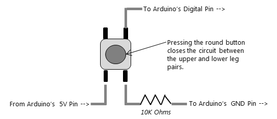
There are many types of buttons available on the market depending upon the usage scenarios. We will use a simple push button for the purpose of learning the fundamentals of wiring a button to a micro-controller and then receiving its input and thereafter triggering a piece of code to make a physical device do something. A typical push button is shown in the following figure for reference.
As shown in the next figure, a simple push button can be easily connected to the Arduino board by following the markings shown in the previous diagram. The important thing to note here is that, the upper leg is connected to a digital pin on the Arduino board. This digital pin will be used to read the signal level (high or low) available from the button leg. So, the digital pin will receive a HIGH signal as soon as the round button is pushed. Until the button is pressed, the signal will be LOW on the digital pin:
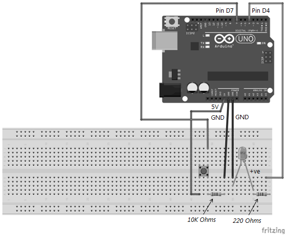
Utilizing the preceding information, let us quickly assemble a prototype to blink an LED as soon as a push button is pressed. You can refer to the breadboard setup shown in the following for reference.
The LED connection details have already been explained previously in this chapter, you may reuse it from the previous sections. The connection details of the push button to the Arduino board are provided in the following table for reference:
|
Push button legs |
Arduino Uno pins |
Comments |
|
Top right leg |
Digital pin D7 |
Connect directly |
|
Top left leg |
N/A |
Not Used |
|
Bottom left leg |
5V |
Connect directly |
|
Bottom right leg |
GND |
Connect via 10K ohms resistor |
Now let us look at the sketch that will read the input signal from the button and send a signal to the LED to glow for a second:
//**********************************************************/
// Step-1: CONFIGURE VARIABLES
//**********************************************************/
int buttonPin = 7;          // D7 used to read input from button
int ledPin = 4;             // D4 used to control LED
int buttonState = LOW;      // Initialize state to LOW to start with

//**********************************************************/
// Step-2: INITIALIZE I/O PARAMETERS
//**********************************************************/
void setup()
{
  Serial.begin(9600);
  pinMode(buttonPin, INPUT);  // D7 will receive input from button
  pinMode(ledPin, OUTPUT);    // D4 will send output to LED
}

//**********************************************************/
// Step-3: MAIN PROGRAM
//**********************************************************/
void loop()
{
  buttonState = digitalRead(buttonPin);  // Read button state

  // If user presses the push button
  // Then state will be HIGH
  if(buttonState == HIGH)
  {
    digitalWrite(ledPin, HIGH);   // glow the LED
    delay(250);                  // wait for 1 second
    digitalWrite(ledPin, LOW);    // switch OFF the glowing LED
  }
  delay(1000);
}
The first step in the preceding sketch is to define the two pins that have been used in the setup. Therefore, two local variables have been defined for storing the pin numbers to which the button and the LED have been connected.
The next step in the sketch is to configure the pins used in the correct mode. Since D7 will be used to read the input from the button, this pin has been configured in the input mode. Pin D4 will be used to send signals to the positive terminal of the LED, therefore it has been configured in the output mode.
Thereafter in the loop() function, the program keeps looping until it finds the button to be pressed using the following line of code:
buttonState = digitalRead(buttonPin); // Read button state
Once a HIGH signal is detected, it means that the button has been pressed. Hence the next part of the sketch is to blink the LED in the portion of the sketch using the following if statement:
if(buttonState == HIGH)
{
  digitalWrite(ledPin, HIGH);   // glow the LED
  delay(1000);                  // wait for 1 second
  digitalWrite(ledPin, LOW);    // switch OFF the glowing LED
}
Thus, we have a simple working prototype whereby pressing a button, we can make LEDs glow. With this example, we come to the end of this chapter. Going forward you may apply the same method to sound a Buzzer or pretty much activate any device on the press of a button!