
Programming the motion of a robotic arm is no small feat. It requires knowledge of trigonometry and kinematics, the study of motion. Moving a robotic arm is complex because you must calculate the angles of each joint required to place the mechanical hand of the robot at its destination. This is typically called forward kinematics because the motion goes forward through the structure. The angle of the shoulder positions the upper arm and elbow, the angle of the elbow positions the forearm and wrist, the angle of the wrist positions the hand, and so on.
Unless you’re a math wiz, this won’t help you much when animating jointed structures in Flash. Fortunately, Flash CS4 Professional introduces an easier approach to the problem; an animation technique called inverse kinematics (IK). Common in higher-end 3D and animation packages, IK is the opposite, or inverse, of forward kinematics. Using IK, you start from the end and work backward. You specify a pose of a jointed structure by positioning its end segment, and let the animation software determine all the joint positions and angles required to create that pose. In Flash, for example, you can drag the hand of an articulated character into position, and Flash then calculates the location and angles of the wrist, forearm, elbow, and shoulder joints.
In the art world, these jointed skeletal structures are called armatures. Armatures are very much like your own skeleton in that they provide the structural foundation for surrounding objects. In sculpture and stop-frame animation, for example, figures in the physical world are often built over armatures to give them support. Jointed armatures are especially important for posable figures, as you can adjust the armatures many, many times without breaking them. Computer animation tools also use armatures. Rather than containing the armatures inside physical models, they are typically superimposed on the figures they control.
In this chapter, you will learn how to create and animate armatures using Flash’s Bone tool. Found in the Tools panel, the Bone tool lets you connect multiple movie clips to form a single posable framework. The tool is very easy to use, requiring little more than a process akin to connecting the dots. To create an armature, you click on one movie clip of the figure to be animated and drag to the next movie clip in the chain. As you’ll see later, the Bone tool connects them together as part of a new skeletal structure.
You can also create armatures that serve as skeletons inside a single shape. For example, you can draw multiple bones with the Bone tool, connecting one point to another, inside a snake-like shape. The armature can then be animated and the shape will deform according to influence exerted by the bones. When working with shapes, you can even control to which bone each anchor point of the shape is connected. When a shape deformation is incorrect, you can use the Bone tool’s close companion, the Bind tool, to change the bone to which a shape anchor point is bound.
Once you’ve completed your armature, you can animate it with the Timeline, control it with ActionScript, or even enable it for runtime manipulation by end users. First, however, it will help to understand how skeletons are made.
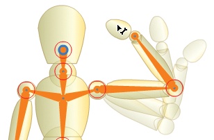
Inverse kinematic structures begin with a root joint—the point around which the entire armature may rotate. For an arm, the shoulder is the logical root joint, however, any skeletal starting point can serve in this capacity. The head, for example, is the root joint of the basic full-body skeleton in Figure 10-1.
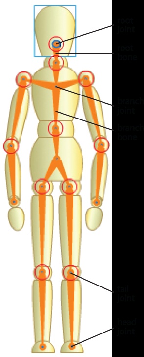
A root bone then spans from the root joint and terminates at the first child joint, such as an elbow. A child bone then spans from that joint to another, and so on, until the armature is complete. Each bone in the armature can have two joints. The tail joint is closest in line to the armature root and the head joint is closer to the end of the armature. Just like your skeleton, the last bone in an armature progression has no head joint. For example, following your arm from shoulder to fingertip, the knuckle of your last finger segment has a tail joint but no head joint.
When a skeletal structure requires more than one linear segment as part of the armature, you can introduce additional joints and bones, called branches. Although the arms and legs in Figure 10-1 contain linear progressions of bones, the skeleton is not complete without branch bones at the sternum and pelvis. These branches help unite the left and right sets of bones into one skeleton.
Because the purpose of inverse kinematics is to move the bones and joints of the armature together to create poses, you can’t drag around pieces of the armature the way you can drag normal display objects. In simple terms, if bones link display objects, you can move them only in directions constrained by the armature. For example, by default, you can’t pull off the head of the sketch mannequin depicted in Figure 10-1 simply by dragging its head away from its body. Similarly, a joint can rotate in 360 degrees unless you take steps to limit its movement to a more natural range. You’ll learn later how to transform bones and constrain joint rotation, but the default limits imposed on display objects by an IK armature already make it easier to pose your objects.
Now that you know a little about armatures, it’s time to create one and apply some basic manipulations. Your first couple of armatures will be for practice, so there’s no need for extensive detail, and the book template is not required.
Create a new FLA (File→New). If you prefer to start with existing assets, open beads_01.fla from the companion source files and skip to step 4.
Using the Oval tool, create a small circle on the Stage and then make it a movie clip. Do not give it an instance name.
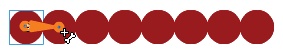
Duplicate this movie clip by selecting it with the Selection Tool and holding down Alt (Windows) or Option (Mac) when dragging it on the Stage. Place the copies adjacent to one another in a horizontal line like a string of beads, shown in Figure 10-2.
Using the Bone tool from the Tools panel, click the center of the leftmost circle and drag it to the next in line, then let go to connect the two circles with a bone, shown in Figure 10-2.
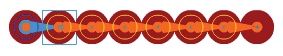
Repeat this process, connecting the second circle to the third circle, then connecting the third circle to the fourth circle, and so on, until all the circles are connected with bones (Figure 10-3).
Save your work as beads.fla. If you wish, compare your file to beads_02.fla from the companion source files.
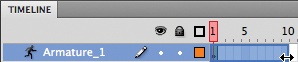
You’ve now completed an IK armature connecting all the circles. If you look at your Timeline (Figure 10-4), you will see that a new layer type, an armature layer, has been created and all the movie clips that became a part of the armature have been moved to this layer.
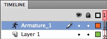
Although you needn’t bother to try this now, you will eventually find that you can’t add anything else to this layer unless it becomes a part of the layer’s associated IK form. Just like a tween layer, the content of an armature layer is restricted to one armature and no unrelated assets.
Now that you have a working armature, it’s time to put it to work. There are two basic modes for using inverse kinematics: Authortime, in which you can pose armatures during authoring mode for animation purposes, and Runtime, which allows the user to manipulation the armature freely while the SWF is running.
To set an armature for authortime manipulation, first select the armature by clicking on its layer in the Timeline panel. Open the Properties panel (Figure 10-5) and set the Type property of the Options section to Authortime.
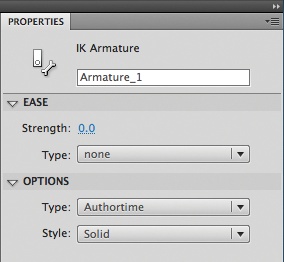
Using the Style setting in the same section, you can switch between solid, wire, and line. Solid displays normal solid bones, as shown in Figure 10-1. Wire displays the same bone shapes, but in outline form. Finally, line displays each bone as a single thin line. Switching between these settings is a matter of preference, but can be useful if the superimposed armature obscures small details in the object you’re trying to animate.
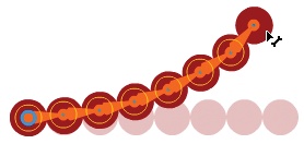
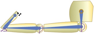
Once you have set the armature Authortime mode, you can drag it around freely on the stage. Figure 10-6 shows the string of beads you created earlier being dragged upward from its original position. You can use Authortime mode to position armatures in static poses, but you can also animate armatures.
To animate IK armatures, you just need to follow the same simple process described in Chapter 5 for tweening symbol instances.
Continue with the beads.fla file you created earlier.
Extend the frame span of the armature layer in the Timeline panel. To do this, grab the end of the armature layer (the end of frame one, in this case) with your mouse and drag it out to frame 100 (Figure 10-7).
Every 20 or 30 frames or so, move the armature on the Stage until you are satisfied with a pose. You will end up with four or five poses, approximately 20 to 30 frames apart.
Save your movie and test it (Control→Test Movie). You should see the beads come to life and move around a little bit like a worm. Compare your file with beads_03.fla.
Using Onion Skinning
To get help with poses, or to preview multiple frames of the animation as you scrub through the Timeline, enable onion skinning in the Timeline panel. This feature can display semitransparent images of the content in the frames before and after the current frame currently in view. The images will appear on the stage while the feature is enabled, making it appear as if you were looking at the content through layers of onion skin. The farther away a frame is from the current frame, the more layers of metaphorical onion skin you’re looking through, and the fainter the art becomes.
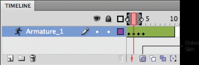
To enable onion skinning, look for the Onion Skin button in the row of icons beneath the frames in the Timeline (Figure 10-8). The playhead will change to show a gray span of frames before and after the playhead. You can change these gray spans to reveal more or fewer frames in either direction. For example, by dragging the right gray span leftward until it stops at the playhead, and the left gray span leftward until five frames are covered, you will be seeing five frames before the current frame wherever you drag the playhead.
Figure 10-9 shows onion skinning applied for an example animation of the sketch mannequin waving. Two prior frames are visible as the current pose is being manipulated.
While previewing your animation, you might notice that it seems a bit expressionless, and perhaps even a bit rigid when the armature changes direction. You may recall from Chapter 5 that you can improve this by applying easing to the tween. Easing is so named because the motion eases into or away from keyframes.
IK animations do not use the Motion Editor, however, so you must apply easing using the Properties panel. The benefit of this approach is that you can apply unique easing between keyframes very easily. Adding easing to IK animations mirrors your experience in Chapter 5 when applying easing to the wheel rotation in the project interface. In that case, easing was also applied in the Timeline panel on a keyframe-by-keyframe basis because you used a classic tween.
To add easing, select a pose keyframe in your armature tween. Any easing applied will affect the frames between the selected pose and the next pose. With the pose keyframe selected, open the Properties panel and look at the Ease section of the armature properties (Figure 10-10).

The Strength setting, which ranges from −100 to 100, determines if you will ease into or out of a pose keyframe. Negative values slow the acceleration of motion as you leave a keyframe. Positive values slow the acceleration as you approach a keyframe. That is, −100 slows the motion closest to the current keyframe, 0 causes no easing, and 100 slows the motion closest to the next keyframe.
The Type setting includes Simple, as well as Stop and Start. Simple slows the motion relative to one pose (either leaving the current pose keyframe or approaching the next pose keyframe, depending on the Strength setting).
The Stop and Start setting slows the motion relative to two poses—both current and next keyframes. When using the Stop and Start easing type, negative Strength values slow the motion at both keyframes, while positive values slow the motion between the two keyframes.
Both easing types have variations called Slow, Medium, Fast, and Fastest. Slow applies the subtlest effect, while Fastest applies a more pronounced affect.
Practice applying easing with your own files, as well as by replicating a sample source file. Using this precreated file, in addition to any of your own experiments, will allow you to compare your results to a matching final version. Try to imagine what will happen from the text descriptions and then consider how well the results matched your expectations.
Open the beads_03.fla file included in the companion source code. This file contains the beads animation you worked with earlier, to which you will now apply easing.
Select the pose keyframe in frame 1. Skew the easing 50% toward the starting keyframe and make the effect relatively pronounced by setting Strength to
−50and set Type toSimple (Fast).Select the pose keyframe in frame 35 and apply the same settings (set Strength to
−50and set Type toSimple (Fast)).Select the pose keyframe in frame 50 and use the same type of tween as in the prior two frames, but this time affect all of the easing at the very start of the animation segment by setting Strength to
−100and Type toSimple (Fast).Select the pose keyframe in frame 70 and apply an ease that slows motion to the greatest extent at the first keyframe, and uses a subtle overall effect. Set the Strength to
50and set Type toStop and Start (Fast).Test your file and compare it to beads_04.fla. The movement of the beads should seem more expressive, particularly as the movement changes direction.
While Authortime mode allows you to pose armatures for tweening, any resulting animation is permanent once you compile your file to SWF. Runtime mode, on the other hand, allows users to manipulate armatures at runtime, without any ActionScript. For example, an animation created in Authortime mode could show a marionette performing a short dance. However, enabling Runtime mode for the marionette could allow a user to control any of its movements.
To enable Runtime mode, simply select the armature layer and, in the Properties panel, choose Runtime from the Options→Type menu. You can try Runtime mode with your own files or use beads_02.fla to experiment.
There are some significant limitations to Runtime mode. First, you can only enable armatures with a single pose keyframe (in other words, no IK tweening animation) for Runtime mode, so preplanning is required. You must either animate your armature using tweening or enable the armature for user manipulation. Second, without ActionScript, only armatures in a FLA’s first frame will work with Runtime mode enabled. Later in this chapter, you will learn the minimum ActionScript required to enable armatures in other frames to function.
By default, armature joints can rotate freely in 360 degrees. Figure 10-11 shows a sketch mannequin in a standard leg pose, as if sitting on a chair. Notice that a complete circle surrounds each joint: hip, knee, and ankle. This visual cue indicates at a glance that the joint can rotate a full 360 degrees.
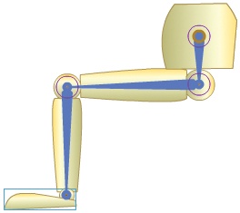
360-degree freedom of rotation provides for nearly limitless posing, but can also be a little too much of a good thing at times. Think about using armatures for humanoid character animations, for example. Restricting joint movement to mimic human skeletal capabilities will make your animation more realistic and easier to create.
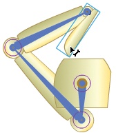
You’ll also end up with fewer awkward poses like the one shown in Figure 10-12. Dragging the foot in a clockwise motion around the pelvis created the pose depicted in this figure. The leg has consequently angled up in front of the body, the knee has bent backward, and the foot is where the spine of a complete skeleton might be. Clearly, this pose is not possible for the average human.
To prevent the ambulatory disaster shown in Figure 10-12, you can constrain the minimum and maximum rotation of each joint in the armature to simulate the range of motion afforded by a human hip, knee, and ankle. To accomplish this, you’ll first add another bone to the foot and then enable the rotation constraint feature for all the joints in the armature. You’ll then set the degree of allowable rotation for each joint and see how these changes more closely mimic natural motion.
The first step in being able to fully constrain the movement of the sketch mannequin’s leg is to create a foot bone. This is a very important concept because it falls outside the default behavior of Flash IK armatures, and is not intuitive. Knowing how and when to take this step will help smooth your use of IK as an animation or interactivity tool.
As you may remember from the Anatomy of an Armature section earlier in this chapter, a bone only has a head joint if it is connected to another bone. In Figure 10-11, the armature ends at the ankle because the foot does not connect to an additional bone segment. Trying to draw a bone within the foot, from ankle to toe, for example, will fail because there is nothing to which the bone can connect.
The lack of a foot bone does not limit manual posing, because the point of rotation for the foot is the ankle. As Figure 10-12 demonstrates, you can manipulate the foot by hand just like any other bone. The trouble begins when you attempt to constrain the movement of the foot or, as you will learn later, try to pose the foot using ActionScript. Because there is no tail joint at the ankle, you cannot restrict the rotation at the ankle or set it with code.
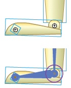
The solution to this problem is to create a placeholder display object at the end of the final shape, to which a bone can connect. The top of Figure 10-13 shows a small movie clip placed at the end of the foot. The alpha value of the placeholder is set to 0 so it doesn’t add a visual distraction to the animated object. The bottom of Figure 10-13 shows a bone connected from the ankle to the “toe placeholder,” which then creates a joint at the ankle that you can constrain. The source file leg_01.fla shows a typical leg armature without a foot bone, while leg_02.fla makes use of this technique to add a foot bone ready for constraint.
To constrain the rotation of a tail joint, you must select a bone, expand the Joint:Rotation section of the Properties panel, and enable Constrain (Figure 10-14). By default, you will be presented with a Minimum rotation value of −45 degrees and a Maximum rotation value of 45 degrees. The desired movement of your bone and joint, however, determines the final values of these settings.
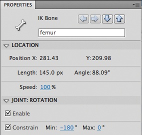
Think of the constraint values of the sketch mannequin’s thigh bone (femur), for example. To mimic the profile view of a human leg, the bone must be capable of rotating approximately 180 degrees at the hip—from parallel to the floor in front of the body to parallel to the floor behind the body.
Note
In addition to constraining rotation, you can alter the speed at which the bone can rotate to simulate weight. A Speed setting of 100% is the baseline speed of movement, so a speed setting of only 25% will make the bone seem much heavier.
Selecting the actual numeric values for the Minimum and Maximum constraint depends on the orientation of the bone. The best way to determine the angles is to look at a close-up of the joint when the Constrain setting is enabled and adjust the values based on visual feedback.
Figure 10-15 shows detailed views of each joint in the leg. Shown from top to bottom are hip, knee, and ankle. In each case, the circle that indicated unconstrained rotation has been replaced with wedges of different shapes, within which a protruding, handle-clad stem sits. The stem represents the current angle of the bone, and the wedge is the span of allowable rotation. In other words, the ends of the wedge stop the stem from moving any further, and the joint rotation is constrained.
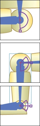
The average human operates under similar constraints. The hip can rotate about 180 degrees, so its wedge is a semicircle. The knee can rotate a bit less than 180 degrees (between full leg extension and contraction when calf meets thigh). The ankle can move about 45 degrees forward (pointing up toward the knee) and 45 degrees backward (pointing away from the knee).
As previously mentioned, the visual feedback at the armature joints is fairly clear, but the numeric values of the constraint angles depend on the orientation of the bone and can take some getting used to.
To begin with, Flash angles of rotation start at 0, which is due east, and move clockwise until reaching 180 degrees, or due west. At that point, the angles change to negative values. Continuing clockwise, the angles span from −180 degrees to 0 degrees. This approach was adopted because it is easier for the computer to rotate to −90 degrees than to rotate to 270 degrees—both of which are due north. You saw this in practice in Chapter 5 when rotating the viewing wheel of the portfolio project interface.
Furthermore, the original location of the stem shown in each joint in Figure 10-15 is determined by the original orientation of the bone. Based on the initial bone position, the stem is created at angle 0, or due east. If you repose the armature, this position changes. Looking at Figure 10-15, for example, the numeric values of the ankle’s Minimum and Maximum constraints are −45 degrees and 45 degrees, respectively. Similarly, the knee constraints are −45 degrees and 90 degrees.
The hip constraints, however, are somewhat unexpected (−180 degrees and 0 degrees). Upon further consideration, this makes sense because the angle values reflected in the wedge overlay are relative to the stem protruding from the wedge. In Figure 10-15, the Maximum rotation has been reached, so the joint can rotate 0 degrees further. The leg can be folded under the hip, however, and it can rotate halfway around the circle to its minimum angle of −180 degrees.
The values of −180 degrees and 0 degrees appear in the Properties panel because the armature was originally created while the sketch mannequin was standing up. If you open the source file leg_03.fla (used for Figure 10-12 and Figure 10-13) and rotate the leg joints so the mannequin is standing, you will see that the hip joint shows an angle of 0 and logical constraint values of −90 degrees and 90 degrees.
Once you have applied the rotation constraints, no armature joint will rotate further than allowed, and the poses will be much more natural. Figure 10-16, for example, shows the result of rotating the leg in the same manner as for Figure 10-12: grabbing the foot and rotating clockwise around the hip. Notice that the result is very different from when the joints were unconstrained; now the constraint angles limit the leg to a natural stopping point at full extension.
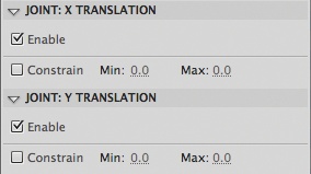
By default, every bone in an armature has a fixed length at the time of creation. Although bones can be rotated around joints, changes to their locations cannot alter the length of a parent bone. However, by enabling joint translation, you can move a bone along the x- or y-axis, changing the length of a parent bone in the process.
Figure 10-17 shows both x and y translation enabled for the right shoulder of the sketch mannequin. The arrows that run parallel to the bone (currently facing up and down due to the orientation of the bone) indicate that y translation is enabled. The arrows perpendicular to the bone (currently facing left and right) indicate that x translation is enabled.
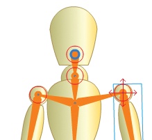
Enabling joint translation is a simple matter of turning on the Enable feature in the Properties panel (Figure 10-18), just as you did for joint rotation. You can also constrain the distance of translation allowed in either direction. If constrained, the arrows shown in Figure 10-17 will change to lines indicating the distance of allowable movement in either each direction.
Note
If you enable both the x and y translation properties of a bone, it is easier to position the bone by temporarily disabling its rotation.
You can transform movie clips, even when they are part of an armature. For example, you can use the Free Transform tool to rotate a movie clip used in an armature without altering the properties of the armature itself. Transforming movie clips associated with an armature is no different than transforming any other display object. The only caveat is that you need to be sure you’re selecting one or more movie clips rather than bones. This may affect the armature, too. For example, if you enlarge a movie clip, the attached bone will lengthen.
Note
If you transform movie clips that are part of an armature animation, these changes will be affected by keyframes like any other tweened property. So, be sure to apply such transformations to any and all relevant keyframes.
You can use this technique to add expression or humor to an animation. For instance, you might subtly rotate and scale arm and leg parts of a robot to make it seem in ill repair as it moves.
If you only want to move a bone or movie clip, while still maintaining its relationship to an armature, you can hold down the Alt (Windows) or Option (Mac) key when dragging the object. This is a quick and easy way to change the length of a bone. It’s also a convenient way to move an entire armature. To do so, just select all pieces of the armature before dragging.
Finally, you can change the visual stacking order of movie clips after they have become a part of the armature. By default, each movie clip that is added to an armature will move to the top of the stack. If you want to change this stacking order, just use Modify→Arrange to reorder like you would with any other display objects overlapping in the same layer.
You can also use the Bone tool to add armatures to shapes. Rather than altering the location or rotation of separate objects joined by bones, as was the case when working with movie clips, manipulating a shape armature will deform the shape itself.
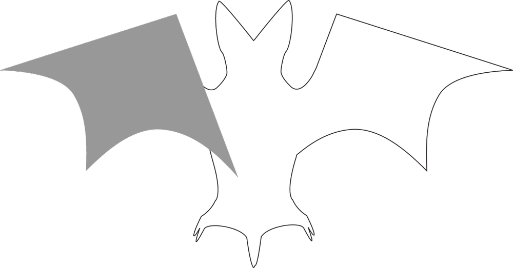
To demonstrate adding an armature to a shape, this discussion focuses on a single simplified bat wing. Figure 10-19 depicts the wing in dark gray, atop an outline of a bat to provide visual context. A three-bone armature will originate in the lower-right corner of the wing, where it joins the body of the bat. To follow along with the discussion, open bat_wing_01.fla.
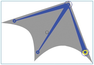
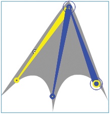
Creating an armature in a shape is no different than linking movie clips with an armature. Using the Bone tool, start where you want your root joint to be and draw bones end to end. Figure 10-20 shows the root joint in yellow, in the lower-right corner of the wing, and the first bone spans up to the top corner of the wing. From that top corner, two additional bones are drawn down to left and mid corners of the web-like shape.
If you are following along, your file should now resemble bat_wing_02.fla.
Dragging the bones outward will deform the shape to an extent that will make it appear like the wing span is elongating and its webbing is becoming taught. Dragging the bones inward will fold up the wing the way a real bat wing might fold in to its body.
However, Figure 10-21 shows that the default deformation of the wing begins to appear uncharacteristic as the left and center bones are moved inward to fold up the wing. This is because anchor points in the wing shape are associated with specific bones by default and their movement of the points doesn’t reflect all of the adjustments made to the armature.
For example, the webbing in the left half of the wing looks OK, but it is being pushed too far to the right because it is not considering the position of the center bone. The webbing in the right half of the wing is deforming in an unnatural-looking way because there are too many points in the shape being affected by the bones.
To correct these problems, you will use another IK tool, called the Bind tool, to associate points in the shape with relevant bones. You’ll also use the Pen tool to remove extraneous points to simplify the morph as a whole.
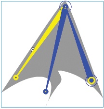
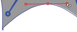
Focusing on the left half of the wing to start, notice that a single point sits at the top of the webbing’s arc. Clicking on this point with the Bind tool changes the point to a larger red rectangle and highlights the left bone with a yellow line (Figure 10-22). These two visual cues indicate that the point is bound to the bone highlighted in yellow. Because the point is only bound to one bone, it is being pushed beyond the center bone during the shape’s deformation. To fix this, you must bind the point to both bones so it can update its position intelligently.
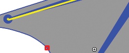
Figure 10-22. Anchor point in wing’s left web is originally bound only to the leftmost bone, indicated by square marker
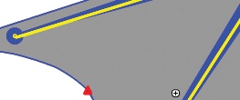
If you click on the point with the Bind tool and drag it to a bone, it will unbind the point from its previous bone and bind the point to the new bone. If you hold down the Shift key when dragging, it will bind the point to the new bone in addition to any existing bindings. Figure 10-23 shows this process in action, binding the point to the center bone as well as to the left bone. After a point is bound to more than one bone, it will display a red triangle when you select it with the Bind tool (Figure 10-24).
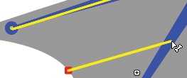
Figure 10-23. Using the Bind tool to bind the anchor point to the center bone in addition to the left bone
If you test the file again and move both left and center bones inward, the deformation of the left half of the wing will be more realistic. You can compare your work to bat_wing_03.fla to check your progress.
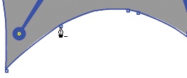
The right half of the wing must be bound in this way, too, but there is a more pressing problem. The arc in the right webbing has three points instead of one, and they are moving independently. To remove the extraneous points, switch to a Pen tool variant, the Delete Anchor Point pen tool, and click to remove the left and right points (Figure 10-25). Only the center point, at the top of the arc, should remain.
After removing the extraneous points, switch to the Subselection tool, click on the remaining point, and adjust its position and control handles to reshape the bottom of the wing into a nice arc (Figure 10-26).
Once you are satisfied with the wing’s shape, you can bind the center point to the center and right bones so it will take the position of both bones into consideration when morphing the shape. Figure 10-27 shows the folded wing after removing the extraneous points and binding the remaining points to the appropriate bones.
The ActionScript required to exert any substantial control over IK armatures is more suited to experienced ActionScript coders. However, you can accomplish two important tasks with minimal code: supporting an armature’s Runtime mode in frames other than frame 1, and posing an armature.
One of the biggest weaknesses of codeless Runtime manipulation of IK armatures is that, by default, they only work in frame 1 of a FLA. Any armatures that you place in other frames will work in Authortime mode, and thus can be used to pose for IK tweens, but they will not work with Runtime mode enabled.
Although ActionScript is still not required to control these armatures at runtime, a small script is needed to register them with the player so it knows the armatures are available for user tinkering.
To try this script, open beads_second_frame_01.fla. This file has been set up with an armature and
stop()action in frame 2, and the armature has already been set to Runtime mode.Test your movie and see that you can’t manipulate the armature at runtime.
Add the following script to the actions layer of frame 2, below the existing
stop()method.1 import fl.ik.*; 2 3 var armtr:IKArmature = IKManager.getArmatureByName("Armature_1"); 4 armtr.registerElements(this.stage); 5 IKManager.trackIKArmature(armtr, true);Save your file as beads_second_frame.fla and test again. The armature will now work in frame 2.
Line 1 of this script imports all the IK classes using a wildcard (*) so the Flash compiler knows where they are when compiling your SWF.
Line 3 creates a reference to an armature by name. Armature_1 is the default name for the first armature created. If your armature is not named the same way, you can either change the script to match the name you are using or rename the armature. You can rename the armature by changing the armature layer name or by clicking on the armature layer in the Properties panel.
Line 4 registers the armature within the scope of the Stage of your FLA so ActionScript can control it, and Line 5 tracks the armature so you can update it as needed.
Flash will automatically register the armature for you when it is in frame 1, but anytime you need to place an armature in another frame, the preceding script is required. You will need to place this code into your portfolio project, too, as you will have an armature on the Help screen.
It’s also possible to control armatures exclusively with code. This is preferable when you want to display animations that must vary from the permanence of the Timeline, without relying on user intervention.
To display motion over time requires ActionScript that is a bit beyond the scope of this text. However, striking individual poses is a relatively straightforward process. To learn the process initially, you’ll control the movement of a simple single-segment armature. Later, in the Project Progress section, you will apply what you’ve learned to pose a three-segment armature.
Note
For an example of using ActionScript to move an armature over time, visit the book’s companion website.
To try this script, open single_bone_armature_01.fla. For simplicity, an armature with one bone has been created in this file, and the armature has already been set to Runtime mode.
Test your movie. Notice that the bone’s initial position (pointing north in the original source file) reflects the last pose you created in the authoring environment. Also notice that you can manipulate the armature at runtime.
Add the following script to the actions layer:
1 import fl.ik.*;
2
3 var armtr:IKArmature = IKManager.getArmatureByName("Armature_1");
4
5 var bone:IKBone = armtr.getBoneByName("ikNode_0");
6 var boneTJ:IKJoint = bone.tailJoint;
7
8 var ikMvr:IKMover = new IKMover(boneTJ, boneTJ.position);
9 ikMvr.moveTo(new Point(0,0));
Save your file as single_bone_armature.fla and test again. The armature will now initially point to the upper-left corner of the Stage. It also remains available to runtime control.
Lines 1 and 3 are the same as in the previous script. Line 1 imports all the required IK classes for the compiler, and Line 3 stores a reference to the armature with an instance name of Armature_1.
Lines 5 and 6 store a reference to the bone and joint you want to manipulate. Line 5 identifies a bone named ikNode_0 in the previously referenced armature. You can change the names of a bone by selecting it and editing its instance name at the top of the Properties panel. Line 6 stores a reference to the tail joint of that bone.
Lines 8 and 9 create an instance of the IKMover class, designed to move bones, and attempt to move the bone to point (0, 0), or the upper-left corner of the Stage. Because the armature is anchored, it can’t be moved to point (0, 0), and strains to get there. The result is that it ends up pointing in that direction.
Warning
The point used in the bone-moving script must be an instance of the Point class. You can’t pass in separate x and y values.
You will initialize an armature in your portfolio project this way, but the armature will be in a movie clip. As such, the coordinates used will be easier to understand if they are translated from values relative to the movie clip to values relative to the Stage. To prepare for this adjustment, see the Local and Global Coordinates sidebar, next.
Local and Global Coordinates
When working with display objects, many properties and methods are dependant upon the scope, or relative location, to which the code applies. For example, consider a movie clip with an instance name of mc, an upper-left-corner registration point placed on the stage at an x coordinate of 20 and a y coordinate of 60 (Figure 10-28).
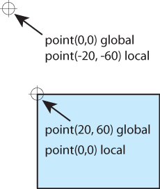
From the Stage’s perspective, that movie clip is at point (20, 60) and the upper-left corner of the stage is point (0, 0)—exactly as you’d expect.
However, from the movie clip’s perspective, those points have different locations. The upper-left corner of the movie clip is no longer point (20, 60), but rather point (0, 0), because that position is now relative to the movie clip.
Similarly, the upper-left corner of the Stage isn’t point (0, 0), but is point (−20, −60) instead. That is, the movie clip remains at the origin of its perspective and the upper-left corner of the stage is 20 pixels to the left and 60 pixels up.
On occasion, you may need to refer to x and y coordinates in another scope. To do so, you can use the globalToLocal() and localToGlobal() methods. These methods translate Points from one scope to another so you don’t have to.
For example, if you wanted to reference the upper-left corner of the Stage from within the movie clip described previously, you would have to use point (−20, −60). However, that location isn’t very intuitive. So, you can translate that information on the fly. You can use point (0, 0), which makes the most sense as the upper-left corner of the Stage, but the location will still be correct if you translate it first.
Using globalToLocal(), you are asking for a global coordinate (relative to the Stage) to be converted to a coordinate at the same location but relative to the movie clip:
trace(mc.globalToLocal(new Point(0, 0)));
//(x=-20, y=-60)
Using localToGlobal(), you are asking for a local coordinate (relative to the movie clip) to be converted to a coordinate at the same location but relative to the Stage:
trace(mc.localToGlobal(new Point(0, 0)));
//(x=20, y=60)
The companion source file, local_global_coordinates.fla, shows a simple example of how this works, and you will also use the technique in this chapter’s Project Progress section, next.

In this chapter, you’ll add an armature to the Help screen so users can point to interface controls with Scaly’s arm. In the next chapter, you’ll populate a dynamic text element with help text based on which on-screen control Scaly’s arm touches.
For this exercise, you’ll need to open the accompanying source file help_01.fla. This file is very much like the default template you usually start with, but with two small exceptions. In the content movie clip, which has been renamed HelpPage for consistency with prior chapters, Scaly’s torso has already been imported from Illustrator. More importantly, a new layer has been added in which Scaly’s arm resides inside a movie clip.
Scaly’s arm has been moved to a higher layer so that it can appear above the portfolio’s viewing wheel when the Help screen loads. You want Scaly’s torso to be cropped by the viewing wheel frame, just as the content from other frames has been cropped. However, his arm must be free to move outside the frame so it can interact with the navigation buttons and sound control at runtime.
You will modify the HelpPage movie clip in the next chapter when you add text. For now, you will focus on turning the arm movie clip into an IK armature.
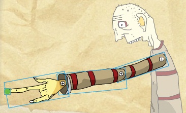
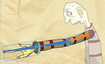
Double-click the arm movie clip to edit its contents. You will see that the arm is composed of four pieces: upper arm, forearm, hand, and a small green dot at the end of the finger (Figure 10-29).
Select the Bone tool in the Tools panel. Enable the Snap to Objects feature by clicking the context-sensitive magnet icon at the bottom of the Tools panel.
Connect your first bone from the upper arm to the forearm. Click in the upperarm movie clip, at the shoulder, and drag to the forearm movie clip, at the elbow. Because you enabled Snap to Objects, the Bone tool will snap to the registration points of the movie clips if you are close enough.
Connect your second bone from the forearm to the hand. Click on the head joint of the previous bone, at the elbow, and drag to the hand movie clip, at the wrist. Don’t worry if the hand movie clip is partially obscured; it will appear at the top of the armature when it is connected to the bone.
Connect your third bone from the wrist to the placeholder graphic. Click on the head joint of the previous bone, at the wrist, and drag to the armature_placeholder movie clip, at the finger. Don’t worry if the armature_placeholder movie clip is partially obscured. It will appear at the top of the armature when it is connected to the bone.
Your armature is now complete. Click on the armature layer so the armature’s properties are visible in the Properties panel. Change the Options Type to Runtime and test your movie. You should be able to drag the arm around the shoulder, unconstrained.
Close your SWF and return to the arm movie clip in the FLA. Now that you have moved the four movie clips that make up the armature to a dedicated armature layer, you can delete the remaining empty layer if desired.
Save your work as help.fla, and compare your file to help_02.fla. Continue with the exercise or, if you’ve had any problems thus far, continue with help_02.fla.
Now that your armature is working, it’s time to constrain its joints to move more like a human arm:
Double-click the arm movie clip to edit its contents.
Using the Selection tool, select the upper arm bone. At the top of the Properties panel, name the bone
humerus. Under Joint Rotation, enable Constrain. Enter values of−130for Minimum and110for Maximum.Repeat the process outlined in step 10 for the forearm and hand bones, using the following values:
Name:
radiusUlna, Minimum:0, Maximum:140Name:
metacarpal, Minimum:−60, Maximum:90
The joints of your armature are now constrained. The final step in preparing your armature for inclusion in the project file is to hide the placeholder at the end of the finger. Open the Library panel and double-click the armature_placeholder movie clip. Select the movie clip inside and set its alpha value to 0.
Test your movie again. When you drag the arm around, it should now be constrained at all three joints to more closely mimic human joint movement, and the placeholder at the end of the finger should now be invisible.
Close your SWF and return to the arm movie clip. If your arm doesn’t behave as expected, look at the visible constraint wedges in Figure 10-30 and compare them with your own. If necessary, adjust the constraint values until the constraint wedge overlays look more like the ones in Figure 10-30.
Save your work and compare your file to help_03.fla. Continue with the exercise or, if you’ve had any problems thus far, continue with help_03.fla.
Your armature is now complete, and it’s time to add it to the project file. You will copy the main content movie clip, HelpPage, from your help.fla file and paste it into the content layer of your main project file, as usual. However, this time you will also create a new layer in the project file, above all other interface layers, for the arm. This way, the arm can be dragged above the navigation buttons and sound control. When the layer drags over these elements, text feedback will display, based on a script that you’ll add in the next chapter.
You’ll end this chapter by adding ActionScript to the main project file that registers the movie clip for runtime operation and presets the arm’s bone positions upon entering the frame:
In your help FLA, unlock the content layer, if necessary, and select the HelpPage movie clip by clicking on Scaly’s torso, then copy it to memory.
While your help.fla file remains open, open your main project file. Scroll to the help section at the end of the Timeline.
In the content layer, at frame 224, add the HelpPage movie clip by using Edit→Paste in Place.
Select the sound layer and add another layer to the Timeline using the New Layer button at the bottom of the Timeline, or by using the Insert→Timeline→Layer menu command. Name the layer helpArmature.
Add empty keyframes (F7) to the helpArmature layer at frames 224 and 231 to match the keyframe locations in the content layer.
Switch back to the help.fla file, select the arm movie clip, and copy it to memory.
Switch to the main project file again and paste the arm movie clip into the helpArmature layer using Edit→Paste in Place.
Double-click the arm movie clip to edit its contents.
Click the armature layer in the Timeline and, in the Properties panel, be sure Runtime is selected in the Options Type setting.
Save and test your movie. After the opening animation is complete, click the Help button and test your armature.
Theoretically, you should be able to use your armature, but it won’t work. This is because runtime armatures will only work in frame 1, by default. You will need to add ActionScript to register the armature. You will also add ActionScript to pose the armature when entering the screen.
In frame 227, add lines 2 through 7 of the following script after the
stop()action already in place in the actions layer. This script will register the armature for runtime operation. If explanation is required, reread the Supporting Runtime Armature Use Beyond Frame 1 segment of the Basic ActionScript section, earlier in this chapter:1 stop(); 2 3 import fl.ik.*; 4 5 var armtr:IKArmature = IKManager.getArmatureByName("Armature_1"); 6 armtr.registerElements(this.stage); 7 IKManager.trackIKArmature(armtr, true);Test your movie again, and navigate to the Help screen. Test the armature by dragging it around. It should rotate in a constrained manner and be capable of dragging over the navigation buttons, sound control, and logo.
All that remains now is to initialize the armature every time you visit the Help screen. Add the following code to frame 227 at the end of the same script you edited in step 26:
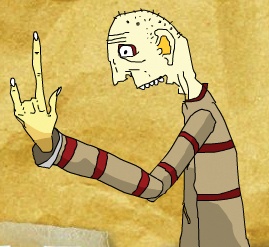
8 presetBone("humerus", arm.globalToLocal(new Point(380,
350)));
9 presetBone("radiusUlna", arm.globalToLocal(new Point(270, 300)));
10 presetBone("metacarpal", arm.globalToLocal(new Point(270, 200)));
11
12 function presetBone(whichBone:String, pt:Point):void {
13     var bone:IKBone = armtr.getBoneByName(whichBone);
14     var boneTJ:IKJoint = bone.tailJoint;
15     var ikMvr:IKMover = new IKMover(boneTJ, boneTJ.position);
16     ikMvr.moveTo(pt);
17 }
To better learn about the script from the previous step, test your file to see its results. Everything will be as it was before, including the ability to drag Scaly’s arm around the screen. However, each time you enter the Help screen anew, Scaly will be pointing up (Figure 10-31).
As for the script described in step 28, it’s very much like the script discussed in the Posing an Armature with Code segment of the Basic ActionScript section, earlier in this chapter. However, there are a few important differences.
First, the code is wrapped in a function in lines 12 through 17, and called in lines 8 through 10. This allows you to pose three bones efficiently, rather than repeating code three times. You’re passing information into the function, including the name of the bone, and the location to which the bone should be set. The bones are given custom names (roughly corresponding to the names of human bones) for clarity only. In your own projects, you can stick with the default assigned names if you prefer.
Second, the armature is already stored in the armtr reference variable determined in the prior script.
Most importantly, however, the points passed into the function are translated from values relative to the arm movie clip to values relative to the Stage. During development, you can look at the Stage and estimate the location of the bones you want to use. However, these coordinates are relative to the upper-left corner of the stage, or point (0, 0). If you do not translate these points into values relative to the movie clip, they will all be offset from the movie clip’s location and the armature will point southeast.
Conversely, if you have to use points relative to the movie clip, they will be difficult to determine when writing your script, and probably confusing later on. To avoid this issue, you can use points that are familiar and easy to determine based on the upper-left corner of the Stage, and then let Flash translate them on the fly to values relative to the movie clip. For more information about translating point values among scopes, see the Local and Global Coordinates sidebar, earlier in this chapter.