Disinfection Systems
Abstract
UV disinfection of potable water for humanitarian assistance/disaster relief (HA/DR) use is a viable technique to reduce or eliminate microbes present in the source water. Chemical oxidants such as chlorine often do not effectively kill spore-forming pathogens such as Giardia and Cryptosporidia. Waters that do not go through filtration can contain large numbers of Giardia and Cryptosporidia; UV disinfection may be the best method to kill/inactivate them. Many commercial UV units that purify water can be used for HA/DR applications. In Europe, as of 2001, there are more than 6000 UV systems that treat municipal drinking water (Bolton and Cotton, 2008). In the United States, there are probably more than 100 utilities using UV disinfection (Wright et al., 2009). This implies that UV systems are reliable and have already been accepted as part of municipal water systems.
4.1 UV Light Systems
UV disinfection of potable water for humanitarian assistance/disaster relief (HA/DR) use is a viable technique to reduce or eliminate microbes present in the source water. Chemical oxidants such as chlorine often do not effectively kill spore-forming pathogens like Giardia and Cryptosporidia. Waters that do not go through filtration can contain large numbers of Giardia and Cryptosporidia; UV disinfection may be the best method to kill/inactivate them. Many commercial UV units that purify water can be used for HA/DR applications. In Europe, as of 2001, there are more than 6000 UV systems that treat municipal drinking water (Bolton and Cotton, 2008). In the United States, there are probably more than 100 utilities using UV disinfection (Wright et al., 2009). This implies that UV systems are reliable and have already been accepted as part of municipal water systems.
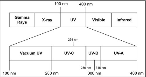
In the electromagnetic spectrum (Figure 4.1), UV light occupies the wavelength range from 100 to 300 nm (USEPA, 2006). Within this wavelength range, UV light is classified into four sub-spectrums: vacuum UV (from 100 to 200 nm), UV-C (from 200 to 280 nm), UV-B (from 280 to 315 nm), and UV-A (from 315 to 400 nm). UV light between 200 and 300 nm, which covers the UV-B and UV-C bands, is the most efficient at killing germs.
When electric current is applied to a gas mixture, the voltage gradient produces a discharge of photons. The wavelength of the emitted light depends on the gas mixture as well as the power level of the lamp used. Mercury is the most common element used in UV lamps. The electric current created by switching on the lamp excites the Hg atoms to a higher energy state. UV light is emitted when these excited Hg atoms return to their ground state. Xenon gas can also emit light in the germicidal range. Mercury vapor lamps are typically classified as low-pressure (LP) (or low-pressure high-output [LPHO]) and medium-pressure (MP). LP lamps produce monochromatic light at the 254-nm wavelength, whereas MP lamps produce polychromatic light between 200 and 300 nm is produced in MP lamps (Table 4.1). As shown in this table, MP lamps operate at very high temperatures, use a more electrical energy, and also produce significantly more light compared to LP lamps. However, an LP lamp has a longer operating life. Bolton and Cotton (2008) report longer operating lives for LP lamps as well as smaller power draws. According to them, the life of a LP lamp is between 8000 and 12,000 h (7000-10,000 h for LPHO lamps), and the life of a MP lamp varies between 3000 and 6000 h. The power draws for the LP, LPHO, and MP lamps, according to Bolton and Cotton, are 0.2-0.4, 0.6-1.2, and 125-250 W/cm, respectively.
Table 4.1
Typical Characteristics of Mercury Vapor UV Lamps
| Parameter | Low-Pressure | Low-Pressure High-Output | Medium-Pressure |
| Germicidal UV light | Monochromatic at 254 nm | Monochromatic at 254 nm | Polychromatic, including germicidal range (200-300 nm) |
| Mercury vapor pressure (Pa) | Approximately 0.93 (1.35 × 10− 4 psi) | 0.18-1.6 (2.6 × 10− 5 to 2.3 × 10− 4 psi) | 40,000-4,000,000 (5.80-580 psi) |
| Operating temperature (°C) | Approximately 40 | 60-100 | 600-900 |
| Electrical input (watts per centimeter [W/cm]) | 0.5 | 1.5-10 | 50-250 |
| Germicidal UV output (W/cm) | 0.2 | 0.5-3.5 | 5-30 |
| Electrical to germicidal UV conversion efficiency (%) | 35-38 | 30-35 | 10-20 |
| Arc length (cm) | 10-150 | 10-150 | 5-120 |
| Relative number of lamps needed for a given dose | High | Intermediate | Low |
| Lifetime (hours [h]) | 8000-10,000 | 8000-12,000 | 4000-8000 |
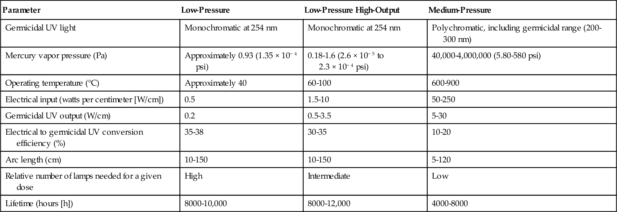
Note: Information in this table was compiled from UV manufacturer data.
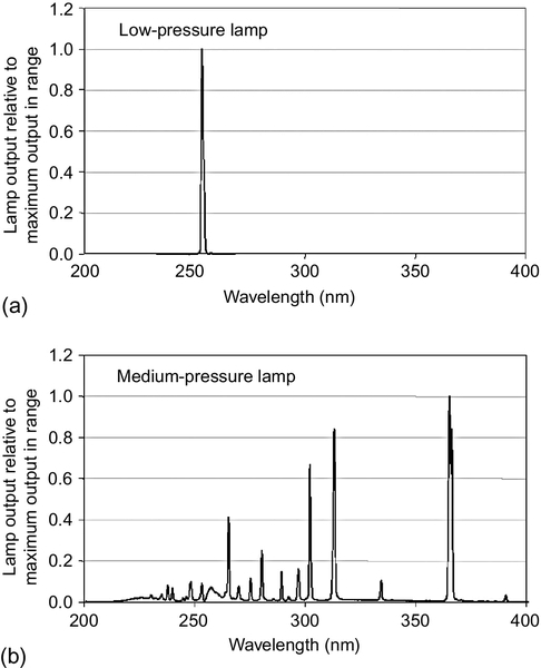
Sharpless and Linden (2001) show that the output from LP lamps is mostly concentrated around 254 nm, and that the output at this wavelength is the maximum output. These lamps do not emit UV light at other wavelengths. However, for MP lamps, the lamp output ranges from 200 to 400 nm, with most wavelengths between 240 and 370 nm. The maximum output of a MP lamp is at 270 nm (Figure 4.2).
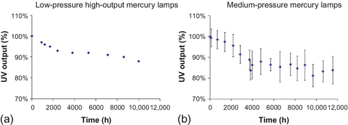
The UV outputs from these two different lamp types also vary over time (Figure 4.3). As the lamps age, the outputs from the lamps decrease. Solarization is a process in which electricity reacts with the mercury in a UV lamp, causing small amounts of mercury and tungsten to be deposited on the inside surface of the lamp’s glass envelope. This process changes the transmittance of quartz because of photo-thermal damage (USEPA, 2006). Manufacturers often provide guidelines for replacing the lamps; most of these guidelines are based on the number of hours of use. As shown in Figure 4.3, the percent reduction in output from MP lamps is much higher than that of LP lamps for same amount of time. However, remember that the output from MP lamps is much higher than that of LP lamps. The output from MP lamps seems to decrease with time in all wavelength ranges.
UV lamps typically have sleeves and ballasts. Ballasts are devices on lamps to limit the amount of current in the electrical circuit (similar to those used in fluorescent lamps to limit the amount of current through the tube). Sleeves protect the lamp from contact with water and allow the lamp to work at proper temperatures. High quality quartz is the material of choice for the sleeves. Quartz allows the transmission of UV light in the 200- to 300-nm wavelength range. The distance between the exterior of the lamp and the inside of the lamp is typically 1 cm.
When a lamp is placed in water, the emitted UV light is absorbed by the water and scattered. UV absorbance in water is a measure of UV light at 254 nm that is absorbed by water over a length of 1.0 cm. Thus, UV absorbance at 254 nm (A254) is a measure of the efficiency of the UV light absorbed by water. As the wavelength of UV light increases, absorbance is decreased.
In addition to UV absorbance, UV transmittance (UVT) is another measure of UV light absorbed by water. UVT is defined as the percentage of UV light at 254 nm passing through a water sample over a distance of 1 cm.
Please note that UVT and A254 are design parameters for UV reactors, and, in each case, the path length of light that expresses A254 or UVT is 1 cm. A spectrophotometer is used to measure UV absorbance as well as transmittance.
If the substance (e.g., water) has light-absorbing capacity, light gets attenuated as it travels through the medium. According to the Beer-Lambert law:
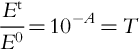
where Et and E0 are transmitted and incident light radiances, A is the absorbance, T is the transmittance, a is absorption coefficient, and l is path length.
Scattering UV light can reduce its germicidal effectiveness. If the water is turbid and contains particles, the light may be backscattered toward the source (USEPA, 2006). UVT will be low in turbid waters.
UV dose is a measure of the UV intensity exposure time. The intensity is reported as mW/cm2, and time is in seconds. Thus, a UV dose is measured in mW-s/cm2, which is same as mJ/cm2. While UV inactivation of bacteria, Cryptosporidia, and Giardia is quite effective, it is ineffective for viruses. UV inactivation efficiency is in the following order: bacteria ≈ protozoa > most viruses > bacteria spores > adenovirus > algae (Bolton and Cotton, 2008).
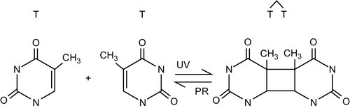
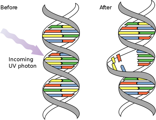
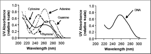
UV light generally inactivates microbes by damaging material in their DNA and RNA. Nucleotides such as cytosine, guanine, thymine, and adenine absorb UV light in the wavelength range 220-300 nm. After UV exposure, dimers (covalent bonds) form between two complementary nucleotides on the same DNA strand, causing damage (Figures 4.4 and 4.5).
Most damage to the DNA of infectious organisms occurs after exposure to UV light in the range of the electromagnetic spectrum. Jagger (1967; cited in USEPA, 2006) has shown that peak absorbance of UV light by DNA material occurs around 254 nm (Figure 4.6).
Bolton and Cotton (2008) state that the relative inactivation response of microbes to UV light is a measure of dimerization of the adjacent thiamine parts of the DNA strand. They define this relative response as the “inactivation action spectrum.” Figure 4.7, which is redrawn using the data of Bolton and Cotton, shows that the maximum inactivation of E. coli, MS-2 phage, and Cryptosporidia occurs in the wavelength range 250–280 where the relative response is the highest in the action spectra.

USEPA (2006) also summarized similar findings that demonstrated a correlation between UV action and DNA absorbance relative to 254 nm across wavelengths from 215 to 300 nm. As can be seen, most absorbance occurs between 250 and 280 nm (Figure 4.8). In MP lamps, these are the wavelengths that produce most of the UV light (see Figure 4.2).

For HA/DR applications, the sizes of UV installations can vary. For short-term use serving large population centers, the systems can be large but portable. For long-term applications, the systems should be small or medium size. Small units can be purchased directly from the vendors and can be used to purify water for one or a few households.
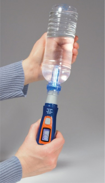
SteriPEN is one of the companies that makes portable water treatment devices, including UV light systems. These units are ideal for emergency preparedness and military, travel, and outdoor recreation uses. The SteriPEN system is used for batch treatment: the UV light is inserted directly into a 0.5- or 1.0-L bottle. The unit is inserted into the neck of the bottle, and the rubberized tapered end of the unit seals the bottle neck. Then the bottle is turned upside down and shaken gently (Figure 4.9). The water-sensing pin on the unit turns on the UV lamp. The timer of the unit is calibrated to the size of the bottle, and the user may be required to press it once or twice. The light will automatically go out after a fixed period (typically 60 s for 0.5 L and 90 s for 1.0 L). The SteriPEN can also be used to disinfect water in a cup or glass. The Ultra model is sold for $99.95, and other models are cheaper. The power used to charge the unit can come from a power outlet, a computer USB port, or from a solar panel. The unit uses two 3.0 V lithium ion rechargeable batteries. The company’s web site (http://www.steripen.com/ultra/) states that use of this product results in a 3-log reduction in bacteria, viruses, and protozoa in the treated water.
Small flowthrough UV systems can be employed for household use. The U.S. National Sanitation Foundation (NSF) certifies UV systems for water treatment, and these systems are slightly more expensive than the standard UV systems. The NSF guideline requires that point-of-use (POU) and point-of-entry (POE) devices for nonpublic water systems use two optional classifications:
(a) Class A systems: These systems use higher amounts of power (40 mJ/cm2) and are capable of disinfecting/removing microbes such as bacteria and viruses to safe levels from contaminated waters, and
(b) Class B systems: These systems use lower amounts of power (16 mJ/cm2) and are designed to provide additional bactericidal treatment of public drinking water or other drinking water (in this case, the input water to units has been already processed by a local health or regulatory agency).
The cost of NSF-certified POU/POE systems range from about $300 to $3700 (http://www.freshwatersystems.com/c-829-nsf-certified-uv-systems.aspx). For example, the Sterilight SV5Q-PA Silver series models are designed for a maximum flow rate of 3.6 gallons/min and use a 110-V power source. These units cost around $329. The lamp life is estimated to be about 9000 h, and the power consumption is 30 W. The disinfection chamber is made of stainless steel, and the unit is 22 in. long and 2.4 in. in diameter with ¾-in. MPT inlets and outlets. The system is rated as Class B (primarily for bactericidal treatment). Trojan Technology’s UVMAX B4-V is a Class B unit that can handle a flow rate of 4.3 gallons/min; it costs about $350. The chamber is 14 in. long and 4 in. in diameter. Power consumption is 36 W from a 120-V source. Trojan’s UVMAX Pro50 light commercial system is a Class A system for light commercial or multifamily use and can handle a flow rate of 50 gallons/min. It costs around $3675. The inlets and outlets use 2-in. MPT, and the chamber is 41 in. long and 4 in. in diameter. The power supply is from a 120-V AC source, and power consumption is 230 W.
Prices for standard UV systems (that are not certified by the NSF) are generally less than $50 for flow rates less than 1 gallon/min. This amount does not include the price of ballasts, which cost between $30 and $50. The lamp power is about 4 W, and the power is from a 120-V AC source. These units are typically small (10 in. long and 2 in. in diameter). Companies such as Pentek, Microfilter, Ultra-Sun Tech, Everpure, PURA, Trojan, Sterilight, and Atlantic UV Corporation make such systems. Most units cost between $100 and $200, with flow rates ranging from less than 1 to 3 gallons/min. These companies also offer larger units that can be used to treat water for small communities or towns.
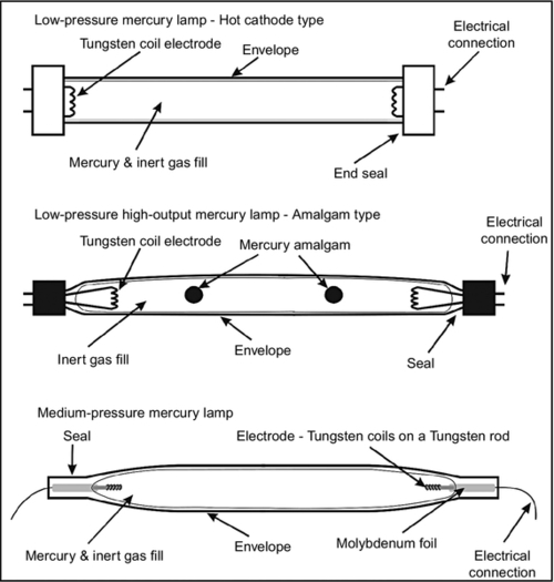
For villages or small towns, medium-size units can be designed using local materials. Locals only need to purchase the UV lamp, the ballast, and other essential parts from the vendors. Figure 4.10 shows the construction of LP and MP UV lamps. However, many commercial vendors also sell such lamps.
Microbes are sensitive to UV light at a given wavelength or narrow band of wavelengths, which determines the response curve of these organisms. For this purpose, the collimated beam apparatus is used to define the relationship between the UV dose and microbial inactivation. The collimated beam reduces the loss of UV light due to internal reflection of the glass surface holding the microbe samples. A suspension of microbes is left in an open petri dish, and the sample is exposed to a UV light source through a long tube so that the light beam is almost parallel and falls perpendicular to the petri dish’s surface. The samples in the petri dish should remain suspended during the exposure time. Commercial vendors sell collimated beam apparatuses. It is also possible to build one without much difficulty. Thus, a homemade unit can be used as a substitute for a commercial collimated beam apparatus (see fig. 3.6, Bolton and Cotton, 2008). Figure 4.11 is a diagram of a benchtop collimated beam apparatus (USEPA, 2006).

One key step in validating the effectiveness of a UV reactor is checking biodosimetry. A challenge microorganism1 (such as bacteriophage MS2 and Bacillus subtilis spores) is selected, and the log inactivation of the organism is measured as a function of UVT, UV intensity, and flow rate of a full-scale reactor. The dose-response curve of the challenge microorganism is developed from bench-scale testing that uses a collimated beam apparatus to plot log inactivation versus UV dose. USEPA (2006) recommends three steps for validating UV effectiveness. Log-inactivation values from full-scale testing are input into the laboratory-derived dose-response data to estimate the reduction equivalent dose (RED), and adjustments to the RED values are made due to uncertainty and bias, which produces the validated UV dose of the reactor for the specific operating conditions. Figure 4.12 from USEPA (2006) provides the details of the validation protocol.

As shown in Figure 4.12, the first step is to figure out the log-inactivation values versus dose-response curve from the bench-scale testing. Then, the log-inactivation data developed from full-scale testing (step 1b) can be inserted into the dose-response curve developed in step 1a to determine the RED. The validation dose is equivalent to the RED divided by the validation factor (VF), which is > 1 as it accounts for biases and experimental uncertainties. USEPA (2006) shows detailed procedures used to calculate VF and validation dose through two examples (see Appendix B of USEPA, 2006).
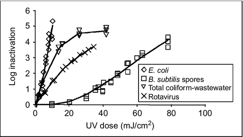
The hydraulics of the reactor affect the delivery of the UV dose. For plug-flow conditions (an ideal reactor), the UV dose is delivered in a narrow band but at a higher occurrence probability than a reactor with poor hydraulic conditions in which a lot of mixing occurs (Figure 4.13). Reactors with narrow dose-distribution characteristics are more efficient than reactors with wider dose-distribution characteristics. Figure 4.14 shows the dose requirements for various organisms, B. subtilis spores being most resistant and requiring higher UV doses. From this figure, we can also see that Rotavirus needs a higher UV dose for the same log inactivation than E. coli and B. subtilis needs even higher dose than Rotavirus for the same log inactivation.

Recent literature suggests that microbes can also repair UV-damaged genetic materials; this is often called photorepair or dark repair (USEPA, 2006). Most bacteria can repair damaged DNA to some extent in the dark. Some of the repair mechanisms include (a) replacing UV-damaged nucleotides by removing thiamine dimers and (b) combining undamaged regions in replicated DNA molecules. Photoreactivation is another repair mechanism in which the light-activated enzyme photolase splits the thiamine dimers, thus restoring the original structure of the DNA (Dulbecco, 1949, 1950; cited in Bolton and Cotton; Kelner, 1949). The absorption of UVA light triggers this reactivation process. Photoreactivation issues are often ignored in the validation of UV reactors. However, Bolton and Cotton (2008) show details of the UV dose requirements at 254 nm for 4-log inactivation of various bacteria. E. coli ATCC 11229 needs only 10 mJ/cm2 without photoreactivation compared to 28 with photoreactivation. For E. coli O157:H7, the required doses of UV light with and without photoreactivation are 6 and 25 mJ/cm2, respectively. For Cryptosporidium and Giardia cysts, the doses without photoreactivation are < 10 mJ/cm2. However, for viruses, the needed doses are much higher without photoreactivation. For example, the adenoviruses require > 100 mJ/cm2 of UV. Even bacteriophages such as PRD1 or MS-2 require 30 and 62 mJ/cm2, respectively. Typically, these doses will be higher with photoreactivation.
A substantial amount of the damage caused by LP lamps can be repaired, while most of the damage caused by MP lamps cannot be repaired. Up to 80% of pyrimidine dimers induced by LP lamps in E. coli can be repaired by photoreactivation (Oguma et al., 2001), while almost no photorepair of pyrimidine dimers is observed after use of MP mercury lamps, indicating that the broader range of wavelengths reduces subsequent photoreactivation (Oguma et al., 2002; Zimmer and Slawson, 2002). Therefore, it is suggested that the wavelengths produced by MP mercury lamps are critical in inactivating enzymes that catalyze photoreactivation (Kalisvaart, 2004; Zimmer and Slawson, 2002), but the precise effective UV spectrum is not known (MP mercury emission spectrum gives hints, though). This issue has not been addressed by UV-light emitting diode (LED) technology.
LED-based UV lamps are slowly becoming available for water and wastewater disinfection. Semiconductor-based Deep UV(DUV)-LED technology is becoming increasingly popular in the field of water purification because of its design freedom, low power needs, wavelength tunability, extended lifetime, and environmental friendliness (Bilenko et al., 2010; Bowsker et al., 2011). Compact DUV lamps based on Ill-Nitride semiconductors (GaN, A1N, InN, and their alloys) are now available, although they are low power (100 mW or less; see Sensor Electronic Technology of Columbia, SC). These lamps offer power distribution over a narrow wavelength (< 12 nm) between 227 and 340 nm (see Bilenko et al., 2010).
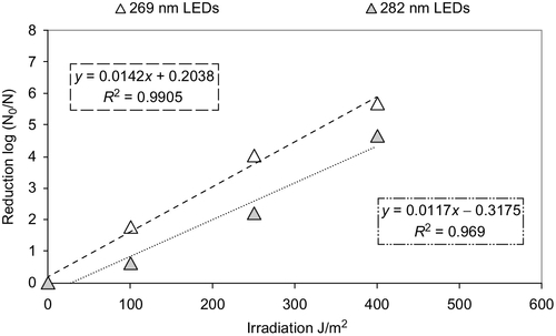
Deep UV semiconductor light emitting diodes (LEDs) are mercury free and can be powered by solar panels or batteries because of the low voltage requirement (6 V). These DUV LED lamps emit between 245 and 365 nm. The best wavelength for water disinfection using DUV lamps is between 270 and 280 nm in a 3-in. diameter by 6-in. long chamber with four DUV LED lamps at each end of the cylindrical chamber. A prototype reactor created by Bilenko et al. (2010) was effective for inactivating both E. coli and MS2 1.6 logs. Kenissl et al. (2010) also tested the efficacy of UV-LED units operating at 269 and 282 nm wavelengths for flowthrough dynamics. The challenge organism was B. subtilis, and the solutions were DI water, tap water (TW), surface water (SW), and secondary effluent (SE). At 269 nm, the researchers observed that most log reduction occurred at irradiations of about 150 J/m2 for all except DI water. With DI water, log reduction continued linearly to 400 J/m2 and then at a slower rate to 600 J/m2. However, at 282 nm, log reductions increased (especially in DI water) all the way to 600 J/m2. Figure 4.15 shows the UV dose versus log inactivation for B. subtilis spores at 269 and 282 nm. It seems the log inactivation was about one log better at 269 nm.
Kenissl et al. (2010) also tested the inactivation of B. subtilis in a flowthrough reactor using DI water. Between 350 and 850 J/m2, log reductions varied from < 2 to 5. The researchers stated that one of the drawbacks of the system is the long exposure time required to treat water. Instead of a few seconds, an exposure time of 3-4 min was necessary. For flowthrough devices, obtaining 3-4 min of exposure time is difficult, especially in household operations.
4.1.1 Advantages and Disadvantages
Disadvantages of UV light systems are that they depend on a constant energy source, little residual disinfecting power is left after treatment, and it is difficult to accurately measure and apply the correct dose of UV. If UV-treated water is to be stored, then chemicals should be added as a disinfectant in order to prevent regrowth of microbes. Another disadvantage is that mercury lamps must be disposed of properly because of the toxicity of Hg; therefore, further investment in UV-LED lamps is recommended, although these lamps are not yet as affordable and effective as mercury lamps. There are also potential risks in UV water treatment, such as exposure to mercury if using a mercury lamp and exposure to UV light from the device, all of which are considered to be minimal. However, for HA/DR applications using small units, there is no standardized mechanism that measures or calibrates how well the equipment is working before and after being installed or throughout treatment.
The advantages of a UV light system are that it is a physical method rather than a chemical one (and thus does not leave any byproducts), it is extremely effective against protozoa, it is inexpensive, and it can treat drinking water relatively quickly. A UV light system also is easy to install and requires little maintenance, which helps keep costs low. UV treatment does not produce any kind of chemical taste or smell and is not sensitive to pH or temperature. It does not take any minerals out of the water, improves taste because it destroys some organics, requires little contact time, has no smell, has no volatile organic compound emissions, and was recently acknowledged to control Cryptosporidium.
UV light can be used as a primary treatment system, and this method has been used in North America and Europe for some time (Palaez, 2011). UV systems can be used alone or with other types of treatments. For example, it is common to use both UV light and ozone/hydrogen-peroxide for groundwater treatment. UV water treatment systems are sometimes produced by companies that also manufacture ozone treatment systems. Chemicals such as chlorine destroy cell structures, interfere with metabolism, and hinder biosynthesis and growth. In contrast, UV light damages a microorganism’s nucleic acid, which hinders its replication, and a microorganism can’t infect a host if it can’t reproduce.
4.1.2 Design Considerations
UV light with an intensity of 90-120 mW/cm2 reduces Giardia lamblia by 1-log, and UV light with an intensity of 90-140 mW/cm2 reduces viruses by 4-log. Because there is no standardized measure to check the effectiveness of UV light systems, water is frequently tested to ensure effluent has low counts of total coliform and HPC (heterotrophic plate count) bacteria. The UV spectrum for disinfection that is most successful and most practical is the UV-B range of 280-315 nm. This range has the highest germicidal action, although UV-C of 200-280 nm can also be used with longer exposure times.
The dose of the UV light must be high enough that the organism’s DNA and RNA will be disrupted. This depends on the lamp intensity (the rate that the photons are delivered to the target), selected wavelength, radiation concentration, water quality, flow rate, exposure time, type of microorganism, and distance to the lamp. Contact time is difficult to measure and is influenced by the flow rate and the reactor hydraulics. However, UV light system manufacturers conduct biodosimetry tests under controlled laboratory conditions and supply the resulting contact time recommendations to purchasers.
Depending on the type of system, UV lamps can run on batteries, solar panels, and electricity. The power supply is important and must be reliable; in situations where power is not reliable, a generator is recommended. As stated earlier, most UV drinking water treatment uses LPHO or MP lamps, which have a lifetime of about 8000-12,000 and 4000-8000 h, respectively. LPHO lamps are more power efficient and run at a lower cost than MP lamps.
Each system should have a flow rate control that allows for a maximum flow that relates to the size of the reactor. A minimum velocity of water is needed to prevent fouling, as mentioned above. This velocity depends on the size of the reactor. Flow rates should be between the minimum and maximum, which should be clearly identified. A minimum flow rate also prevents overheating of the lamps.
To ensure that the challenge protozoa are not a concern, it is best to use a functional system that was previously built and tested instead of building a system locally. This allows users to have confidence in the system. Users can also install two units so that one unit can treat water while the other is being cleaned or maintained; this will also be helpful in low-flow situations. Most preassembled systems come with automatic cleaners and alarm systems, which are easy to replace.
In order to prevent biofouling, the UV light reactor should remain on, and the system should never be left full of stagnant water for an extended period, or a biolayer may form. If users follow the recommended cleaning protocols and wipe the lamp surface 1-12 × an hour, fouling can be significantly decreased. Mineral or inorganic fouling is difficult to predict and stop; this process is rather complicated, and it is recommended that users properly clean and maintain the reactor for the best results and to increase the life expectancy of the system. Another way to reduce biofouling is to maintain a constant flow rate that is appropriate for the system. If the flow rate is too low, a biolayer can begin growing, and, if too fast, the light does not have enough contact time with the water to disinfect it.
Knowing the pH, alkalinity, hardness, iron (Fe) content, and magnesium (Mg) content of the water before it reaches the UV reactor will help determine what kind of fouling will occur and how best to resolve the effects. These factors do not affect the disinfection process itself, only the obstruction of the UV light when a crust forms. For example, one wiper sweep every 15 min for a total calcium and hardness of less than 140 mg/L and with an iron of less than 0.1 mg/L.
4.1.2.1 Maintenance
UV units are simple to maintain. The lamps should be replaced yearly or when efficiency decreases to 70%. Users should inspect the lamps often, clean them every 6 months, and replace the O-rings, valves, switches, and ballasts as needed. An operator should monitor these systems and carefully watch the water’s turbidity and color because these characteristics relate to the system’s efficiency. Users should also carefully monitor the water’s calcium content because it also has a negative effect on the system’s performance.
4.1.2.2 Cost Per Unit Water Treatment
Costs for operating and maintaining UV light water treatment systems vary from $0.02 to $2.35 per m3 (Palaez, 2011). These systems are affordable for low-income households and communities, and these systems can be used in environments with minimal electrical and water infrastructure.
Initial investments vary, depending on the size of the units and the addition of monitoring units. The estimated cost of a household system can be as low as $50; for use in a small community, a high volume unit that incorporates the most up-to-date technology can cost as much as $86,419. The average cost for a community-size UV water treatment system is between $300 and $900 (Palaez, 2011).
4.2 Silver-Impregnated Activated Carbon
Silver in various forms has been used as an antibacterial agent for centuries. Silver is used as a biocide in water treatment as well as in other applications such as dyes and paints, varnishes, textiles, cosmetics, cleaning agents, baby bottles, washers, and more. For example, the “Barbicide” used in barber shops contains silver nitrate along with alkyl dimethyl benzyl ammonium chloride. Use of silver nitrate as a germicidal agent dates back to the late 1800s (Kim et al., 2009). Silver in various forms is used in cartridge filtration systems that employ activated carbon to absorb contaminants. Silver is primarily used to inhibit bacterial growth on the carbon’s surface.
Cartridge filtration systems are the most common point-of-use water treatment devices that use various types of filters in designated housings to produce potable water. Although home-use granular activated carbon (GAC) filters became very popular in the 1970s, these systems did not address bacterial growth (Taylor et al., 1979). Geldreich et al. (1985) showed the colonization of bacteria in POU devices based on daily use or nonuse. None of the filters used in their 3-year study contained silver impregnated activated carbon. They found daily variability in the release of bacteria from the devices and colonization of the microbes during nonuse periods. Brewer and Carmichael (1979) showed that microbial populations adhere to and accumulate on a GAC surface during water filtration and bacterial endotoxins can be transmitted to the filtered water.
Research on the use of silver-impregnated carbon filters for water treatment dates back to the 1970s in the United States. Regunathan and Beauman (1987) reported that adding silver to GAC filters reduced bacterial counts compared to filters without silver. However, in their study, the control counts were low for coliforms. They also tested filters containing copper but reported that the antimicrobial effects of copper were much less than those of silver. The GAC in these filters has a large surface area and can serve as a broad-spectrum adsorption bed. Such systems are often used in HA/DR scenarios as well as in developing countries. In HA/DR applications, the source waters are typically surface waters. For household use in developing countries, the source water is typically city water fed to the homeowner’s tanks or shallow ground water obtained from a well located on the homeowner’s property. There is concern about whether the silver is effective over a prolonged period as well as whether it can leak out of the filters and into the treated water.
Bell (1991) shows that contact time was crucial in reducing E. coli in water treated with filters containing silver nitrate or silver ions. The killing action of typical filters is not effective because the contact is limited to minutes for household filters. Bell also points out that several studies have raised questions about the efficacy of silver-impregnated activated carbon filters and that most published data have been negative about the use of silver to control bacteria. At 50 μg/L silver concentration and at 1 h contact time, Salmonella was reduced by 5 logs, Pseudomonas aeruginosa was reduced by 50%, and there was no reduction of polio viruses. Reasoner et al. (1987) described a USEPA study of three filters with silver and four without silver that were used for 11 months. The heterotrophic plate count (HPC) for the influent during this period was about 6000 per mL. However, the effluent HPC ranged from 800-62,000 for filters with silver to 32,000-107,000 for filters without silver. All these units showed an increase in the bacterial population.
Currently, many vendors provide silver-impregnated activated carbon filters for home use. These filters typically cost less for home use, and volume discounts are available. Pentek manufactures silver-impregnated GAC filters with nominal pore sizes of about 0.5 μm. These filters have a diameter of about 73 mm and a height of 248 mm, and the design flow rate is 1 gallon/min (Figure 4.16). The life of the filter is about 1000 gallons. This filter fits into a 10-in. filter housing.

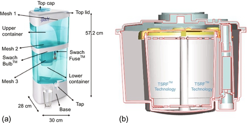
Often, high-quality coconut GAC filters impregnated with silver are used in large filter casings. However, the end user must be aware that silver leaks out of the carbon during the water filtration process. Contact times and the amount of carbon are the two factors that determine the antimicrobial action of these filters. Figure 4.17a shows a filtration unit that uses nano-silver for bacterial reduction. The filter is made for household use by the Tata Company in India (http://www.tataswach.com/). This filter has a bulb in the center through which the source water passes under gravity (Figure 4.17b); the lower unit is a container to hold the filtered water. Two such units were tested in the authors’ laboratory to filter settled stream water.
The silver on the top and bottom of the filter bulb after a few weeks of use is shown in Figures 4.18 and 4.19. Only a few silver nanoparticles are present on the husk in Figure 4.18 compared the number in Figure 4.19. As the water is filtered through the bulb, the nanoparticles of silver present in the top section of the filter are washed away. Silver release from silver-containing antimicrobial textiles has been documented by Lorenz et al. (2012). They investigated eight commercially available silver-containing textiles with total silver contents ranging from 1.5 to 2925 mg/kg. Four of the eight textiles released silver, and the majority of the released silver (34-80%) was in the form of particles > 450 nm.


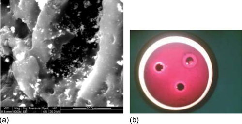
Bandopadhyaya et al. (2008) provide some details of how silver-impregnated GAC filters are prepared for water purification. They prepared AgNO3 solutions (0.001-1.5 M) and added 1 g of GAC to 20 mL of AgNO3. The solution was kept in the dark to reduce photodecomposition of the AgNO3. After 24 h of carbon impregnation, the samples were washed with water to remove any loosely adsorbed AgNO3 from the GAC. The GAC was dried on a filter paper in a vacuum desiccator. By adding 0.2 M NaBH4 to the GAC, the AgNO3 was chemically reduced to Ag particles. Excess NaBH4 was washed away, and the GAC was dried. Figure 4.20 shows (a) scanning electron microscope (SEM) image of silver on GAC as depicted as white spots and (b) inhibitory zones formed by this Ag-GAC against E. coli.
As mentioned earlier, the drawback of silver-impregnated GAC is the loss of silver as water passes through the filter. Manufacturers of antibacterial carbon fibers (Oya et al., 1993; Park and Jane, 2003) have created procedures to prepare silver-containing activated carbon fibers (ACF) for antibacterial use. Zhang et al. (2004) suggest that Ag/ACF systems do not work well because the silver is normally much larger (20 nm to 1.5 μm) than the pores on an ACF (about 2 nm). Because the silver is not trapped in the pores, it is easily washed off. Zhang and colleagues recommend using carbon aerogels (CA) as alternatives to ACF because the CAs have low bulk densities and high surface areas and are highly porous. The bulk density of a CA is typically between 0.2 and 0.4 g/cm3, and the silver content can be adjusted as desired. Zhang and colleagues used silver nanoparticles on the CA bed, which was dried in ambient pressure. They tested the antibacterial properties of CA and found that at 1.4% Ag, 5 mg of Ag-doped CA can kill nearly all E. coli in a 10-mL solution at 1.92 × 10⁵ CFU/mL in 2 h.
Srinivasan et al. (2013) synthesized Ag nanoparticles under UV light by reducing AgNO3 with sodium citrate. The Ag particles had a mean diameter of 28 nm with a standard deviation of 5 nm. The activated carbon was treated with oxygen plasma to increase polar functional groups. This treatment increased the number of Ag nanoparticles on the external surface of activated carbon compared to inside the pores. FTIR spectra showed an increase in the amount of oxygen-containing functional groups such as C![]() O or C
O or C![]() O from about 22% to 31%. In their plate assay and shake flash tests, these researchers found a one-order increase in the death rate of E. coli.
O from about 22% to 31%. In their plate assay and shake flash tests, these researchers found a one-order increase in the death rate of E. coli.
4.2.1 Cost Considerations
A comparison of the cost of producing a gallon of water using various filters for under the sink, on the counter, or elsewhere can be found at WaterFilterComparisons.com. For nonbacteriostatic filters, the cost per gallon of water varies between 9 and 26 cents. The cost for operating countertop units varies between 12 and 16 cents per gallon. Initial investments vary depending on the brand.
The Pentek® brand 10-in. silver-impregnated GAC filter costs about $25. The housing, tubing, prefilters, and other equipment can cost another $100. The flow rate is 1 gallon/min, and the filter is designed to produce 1000 gallons of water. If the prefilters are replaced at the same time as the GAC filter, then the cost for 1000 gallons of water is around $50, which translates to about 5 cents per gallon. If the filters perform at 50-75% of the projected efficiency, the cost per gallon is about 8-10 cents.
4.3 Electrochlorination Systems
Electrochlorination is a technique used to produce sodium hypochlorite (NaOCl) from salt water or sea water by running electric current through it. NaOCl is bleach, which is used in household applications and is also widely used in water treatment processes. The product has a pH between 6 and 7.5 and is stable. Typically, the energy source is electricity or a battery. The chemical reaction is:
At anode, free chlorine is generated using the following reaction:
At cathode, H2 is produced in the aqueous media as follows:
In the anode reaction, Na+ ions and Cl2 gas are present in excess quantities. OH− ions migrate from the cathode region to the anode region and react to form:
The balanced chemical reaction can be written as:
The Cl2 gas produced at the anode is primarily used to form NaOCl; however, H2 produced at the cathode is lost to the atmosphere.
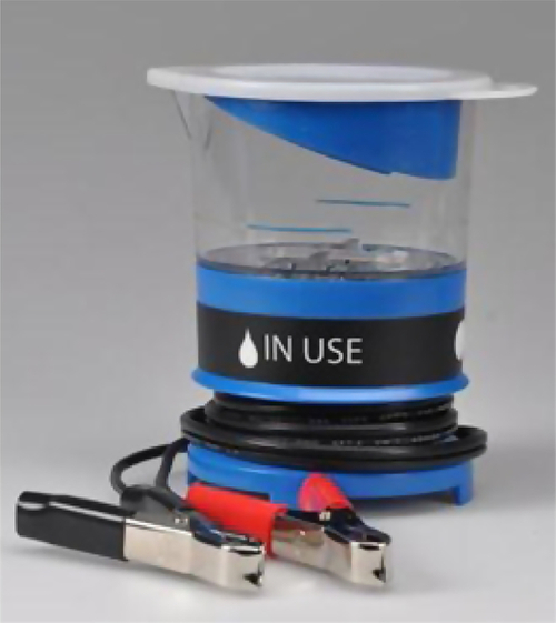
Either pure NaCl is added to deionized water, or seawater is used to make bleach. Several commercial companies make electrochlorination units to treat drinking water. Cascade Designs and Miox Corporation make small units that have been used for HA/DR applications (Figure 4.21).
4.3.1 Byproduct Formation
If seawater is used for electrochlorination, bromate may be created:
More recently, electrode materials have been investigated for their ability to produce different types of oxidants for disinfection. Jeong et al. (2009) examined boron-doped diamond (BDD), Ti/RuO2, Ti/Pt-IrO2, and Pt as electrodes. The efficiency of −OH production, as determined by para-chlorobenzoic acid (pCBA) degradation, was, in order: BDD ![]() Ti/RuO2 ≈ Pt. No significant production of ∙OH was observed at Ti/IrO2 and Ti/Pt-IrO2. The ∙OH was found to play a key role in O3 generation at BDD, but not at the other electrodes. The production of active chlorine was, in order: Ti/IrO2 > Ti/RuO2 > Ti/Pt-IrO2 > BDD > Pt. Li et al. (2011) compared electrochemical disinfection with ozone treatment, chlorination, and monochloramination of treating drinking water. They found that, under optimal conditions, CT (concentration of disinfectant × contact time) values of a 4-log E. coli inactivation were 33.5, 1440, 1575, and 1674 mg min/L for the electrochemical process, ozonation, chlorination, and monochloramination, respectively. Dalaedt et al. (2009) evaluated the disinfection of E. coli and L. pneumophila in tap water (which was seeded with these organisms) using an electrochemical cell (Ecodis®) with an internal volume of 1 L. Disinfected tap water was used in the electrolysis cell to generate the oxidant. The small Ecodis cell was able to disinfect 150 L of water in an hour. The free oxidants in the water were measured using a Hach® test model DR/3 and Hach DPD free chlorine reagent powder pillow. The chloride in the tap water was sufficient to produce enough free chlorine for disinfection.
Ti/RuO2 ≈ Pt. No significant production of ∙OH was observed at Ti/IrO2 and Ti/Pt-IrO2. The ∙OH was found to play a key role in O3 generation at BDD, but not at the other electrodes. The production of active chlorine was, in order: Ti/IrO2 > Ti/RuO2 > Ti/Pt-IrO2 > BDD > Pt. Li et al. (2011) compared electrochemical disinfection with ozone treatment, chlorination, and monochloramination of treating drinking water. They found that, under optimal conditions, CT (concentration of disinfectant × contact time) values of a 4-log E. coli inactivation were 33.5, 1440, 1575, and 1674 mg min/L for the electrochemical process, ozonation, chlorination, and monochloramination, respectively. Dalaedt et al. (2009) evaluated the disinfection of E. coli and L. pneumophila in tap water (which was seeded with these organisms) using an electrochemical cell (Ecodis®) with an internal volume of 1 L. Disinfected tap water was used in the electrolysis cell to generate the oxidant. The small Ecodis cell was able to disinfect 150 L of water in an hour. The free oxidants in the water were measured using a Hach® test model DR/3 and Hach DPD free chlorine reagent powder pillow. The chloride in the tap water was sufficient to produce enough free chlorine for disinfection.
Jeong et al. (2007) report that there has been tremendous interest in recent years in the electrochemical disinfection of water. Most efforts have been geared toward generating free chlorine electrochemically, and research on oxidant production without chlorine is scarce. Jeong et al. mention that disinfection occurs in two stages: (a) electrosorption of negatively charged microbes to the anode surface, followed by (b) a direct electron transfer reaction. As electrolysis continues, the inactivation rate becomes slower than in the first phase but remains steady. Hydroxyl radical plays a significant role in disinfection. Although these oxidants do not leave significant residuals, they also do not form other byproducts such as bromate when seawater is used for electrolysis.
Studies show that perchlorate and bromate are produced by electrolysis of seawater (Oh et al., 2010). Perchlorate concentrations were low compared to bromate concentrations. Bromate is a regulated compound, and the current USEPA standard for bromate in drinking water is 0.01 mg/L annually. The molecular weight of bromine is 79.9 g/mol, and that of hypochlorite ion and bromate are 51.5 and 127.9 g/mol, respectively. A typical concentration of Br− in seawater is 67.3 mg/L (0.84 mM) at 3.5% salinity. Also, 3 mol of hypochlorite ions react with 1 mol of bromide to form a bromate ion. Thus, 0.84 mM (107.7 mg/L) bromide can theoretically produce 0.84 mM bromate if sufficient OCl− is present. This can far exceed the MCL.
Many large manufacturers produce units for electrochlorination/oxidation. Anodic oxidation (as it is often called) is frequently used in these devices. Hydrosystemtechnik GmbH of Bruckmuehl, Germany, produces such units, which have been deployed in various locations. Kraft et al. (1999a) compared the production of hypochlorite from dilute chloride solutions using platinum- and iridium oxide-coated titanium expanded metal electrodes used as anodes. They found that the titanium electrode coated with iridium oxide produces hypochlorite at a higher rate than the titanium electrode coated with platinum. Kraft et al. (1999b) also found that the production of hypochlorite dropped off with increased temperature, but an increased rate of production was associated with higher rates of flow through the electrode assembly. In addition, Kraft et al. (2002) stated that calcium coating on the cathode reduced the efficiency of disinfection. They suggested using the cathode as a sonotrode, which can be cleaned while it is connected to an ultrasonic unit (Figure 4.22).

4.3.2 Cost Considerations
The cascade unit costs about $100, and it needs a battery or some sort of DC voltage source (i.e., a solar panel with a battery) to function. The only chemicals needed to generate NaOCl are pure salt (operators should avoid using sea salt as it contains bromide ions, which can form bromate). In India (Mumtaz et al., 2012), the cost of electrolytical defluoridation is about $0.15 per 1000 L of water. Capital costs of units that use batteries can be around $1500. A solar panel set-up for this system would cost about $2000 more. Kalf Engineering Pte Ltd, in Singapore, makes “elysisPURE” electrochemical units that are used in water treatment operations for continuous flow systems. These devices, according to the manufacturer’s web page, can produce hypochlorite with chlorine at > 8000 mg/L. The electrodes last for 5 years or longer, and the unit’s life is about 7 years. The power needed to produce 1 kg of chlorine is about 4.2 kWh, and the salt needed is about 3.5 kg. The unit should be cleaned with acid once a year. The elysisPURE series NT-H-PTET-B960 units produce 40 kg of sodium hypochlorite per hour at a chlorine concentration of 8000 mg/L. Kalf Engineering also has other units with chlorine production rates ranging from 1 to 2000 kg/h.
4.4 Chlorinators
Chlorine is an inexpensive form of water treatment. It is available in several forms and can easily treat large as well as small volumes of water. Because of chlorine’s versatility, chlorine disinfection devices can be used for to treat water for both households and communities (Backer, 2008; Loo et al., 2012).
4.4.1 Liquid Chlorine as a Disinfectant
Household bleach can be used to disinfect drinking water. A specific number of drops should be added to the water, depending on the concentration of the chlorine in the bleach solution, the quantity of the water being treated, and the quality of the water being treated. Water quality factors that increase the necessary chlorine dose include increased turbidity, increased pH, and decreased temperature (Burch and Thomas, 1998). As turbidity impedes disinfection, water should be filtered using a cloth filter or a coffee filter before chlorination. Inactivation of microorganisms such as Vibrio, Salmonella, and Shigella generally requires a contact time of 30 min, depending on the dose used. Chlorine has been found to be fairly ineffective against protozoans because they can form spores, so a much longer contact time of 4 h is required. Even with the longer contact time, chlorine might still be ineffective against some microbes, such as Cryptosporidium (Table 4.2).
Table 4.2
EPA (2006) Recommendations for Disinfecting Contaminated Water Using Household Bleach
| Available Chlorine | Drops Per Quart-Gallon of Clear Water | Drops Per Liter of Clear Water |
| 1% | 10 per quart-40 per gallon | 10 per L |
| 4-6% | 2 per quart-8 per gallon | 2 per L |
| 7-10% | 1 per quart-4 per gallon | 1 per L |
Double the amount of drops if water is murky or turbid.
An advantage to using chlorine as a disinfectant is that it leaves chlorine residual in the water. This residual helps prevent recontamination of the water if it’s stored correctly. Chlorination using sodium hypochlorite (NaOCl) was found to improve stored water quality after the Indonesian tsunami (Gupta et al., 2007; Loo et al., 2012). NaOCl can also be used for cleaning storage vessels, but, in some cases, it did not prevent recontamination of storage vessels (Steele et al., 2008).
When water is treated as a batch solution with chlorine drops, little maintenance of the treatment device is required. Filtering the water and adding the chlorine drops does not require skilled operation. Chlorine degrades quickly, so the treated water needs to be stored in a closed container in a cool, dark place so the degradation process is slowed. Even then, the half-life of chlorine is 2 months. Because of this quick degradation, chlorine supplies need to be replenished often to ensure sufficient disinfection. The costs associated with chlorine use are mainly derived from the cost of replenishing the chlorine. Labor takes around 20 min to produce a batch of disinfected water and thus is not highly time sensitive (Burch and Thomas, 1998). However, if turbid water must be filtered, costs and labor will increase.
4.4.2 Chlorine Tablets
Loo et al. (2012) and Berg (2010) noted that chlorine in tablet form such as sodium dichloroisocyanurate (NaC3N3O3Cl2, abbreviated as NaDCC) has been widely used in emergencies, and studies have shown NaDCC to offer advantages over liquid chlorine, such as greater stability, safety, and convenience because of its single use packaging and light weight (Clasen and Edmondson, 2006; Lantagne et al., 2010). Tablets also have a longer shelf life and lower transportation costs than liquid chlorine. McLennan et al. (2009) compared four types of disinfection POUs for emergency water treatment and found that none of the disinfection technologies, NaDCC included, provided a large enough chlorine residual for safe water storage.
Similar to liquid chlorine, the dosage of chlorine tablets depends on factors such as temperature, turbidity, presence of NOM (natural organic matter), and the type of bacteria/viruses (Abbaszadegan et al., 1997; Feachem et al., 1983; LeChevallier et al., 1981). NaDCC tablets have been shown (Clasen et al., 2007; Jain et al., 2010) to reduce risk of diarrhea by 48% in Zambia. However, in a recent epidemiological study in Ghana, no significant reduction in diarrheal risk was associated with using NaDCC tablets (Jain et al., 2010). These conflicting findings regarding diarrhea reduction could be attributed to different levels of water contamination as well as the procedures used to store the water (Loo et al., 2012).
Loo et al. (2012) also noted another form of available chlorination technology: water-insoluble polymeric beads that release halogen when in contact with microbes (Chen et al., 2003; Mazumdar et al., 2010). The disinfection mechanism is probably a diffusion-induced release of halogen. These biocidal beads can be integrated into filtration processes for controlled flow rates and predictable performance. Nevertheless, NaDCC tablets are the preferred chlorination technology because these tablets are easy to handle and rapidly deployed during acute emergencies.
Aquatab manufactures NaDCC tablets for emergency disaster relief. The NaDCC dose and the corresponding amount of water that it will treat are shown in Table 4.3. Tablets are dropped in water, and the water is stirred and then allowed to sit for 30 min.
Table 4.3
Aquatab Concentrations for Emergency Response Applications (Medentech)
| Concentration | Quantity of Water to Be Treated |
| Aquatabs 8.5 mg | 1 L |
| Aquatabs USA | 0.8 quarts |
| Aquatabs 33 mg | 5 L |
| Aquatabs 67 mg | 10 L |
| Aquatabs 167 mg | 20 L |
| Aquatabs 1.67 g | 200 L |
| Aquatabs 8.68 g | 1000 L |
| Aquatabs Granules | All volumes greater than 1000 L |
4.4.3 Disadvantages of Chlorination
A disadvantage of using chlorination to disinfect drinking water is the potential formation of harmful byproducts if too much chlorine is used and there are organic compounds in the water. Chlorine byproducts can form carcinogens and trihalomethanes (THM), but a study by Lantagne (2010) found that THM levels created by NaDCC tablets and NaOCl were below acceptable levels specified by World Health Organization.
Another disadvantage of chlorination is that chlorine is ineffective against Cryptosporidium and Mycobacterium (Backer, 2008; Clasen et al., 2007), both microbes that can cause illnesses.
For all treatment technologies that include chlorination, the required dose depends on the amount of water being treated. Without knowing the size of water container, it’s difficult to know how much chlorine to add, resulting in the risk of overdosing or underdosing the water. A study by Clasen et al. (2007) found that a 67-mg tablet was an appropriate dose in a 20- to 25-L water container, but this size tablet was too much chlorine for a 12- to 14-L container. It’s interesting to note that the values Clasen thought were too high do not correspond with the values in Table 4.3, the dose values suggested by the manufacturer. The dose also depends on the water’s turbidity. The authors agreed that overdosing was less risky than underdosing, which would result in insufficient disinfection. However, overdosing could result in less acceptance of chlorine disinfection because of the strong chlorine taste and smell that result from the free chlorine residuals (Clasen et al., 2007).