
4
Power extraction and tritium self-sufficiency
Abstract
Major requirements for a future fusion power plant are to ensure the extraction of the fusion power for electricity production and to provide the whole T necessary to sustain the thermonuclear reaction during the plant lifetime.
Blanket first wall and divertor targets have to be designed to sustain high heat flux in small surface regions facing the plasma; thick structures have to surround the plasma to capture the neutron energy and protect vacuum vessel and magnets. All these components have to be efficiently cooled to respect strong additional requirements to ensure an efficient operational regime for the power conversion system.
The neutrons generated by the plasma have to be used for T generation; for this scope blankets are filled by Li compounds in solid or liquid form. To reach the tritium self-sufficiency the blanket needs an accurate and clever design of the breeder zone and an accurate material selection. Furthermore, recovery time of T that has to become available for the fuel cycle have to be minimised, avoiding large inventories in reactor and in the fuel processing plant.
The development of these technologies is the key issues for the development of a first generation of fusion devise after ITER.
Keywords
Breeder technology; Breeding Blanket; DEMO Programme; FPP; Future fusion power plant; ITER test blanket; Tritium self-sufficiency4.1. Introduction
A future fusion power plant (FPP) has to accomplish two fundamental functions: to ensure the extraction of the fusion power for electricity production (or industrial use of the heat, eg, H production) and to provide the whole tritium necessary to sustain the thermonuclear reaction during the plant lifetime. These two functions are accomplished almost entirely by the blanket system that becomes the key element for the development of an FPP. Blankets will cover more than 80% of the surface surrounding the burning plasma, and their coolant loops will collect 80–85% of the total thermal energy generated in the plant. The remaining thermal power will be collected mostly by loops associated with the divertors and a small percentage in systems associated with the Vacuum Vessel. The need of electricity production imposes very strong requirements to the coolant loops of the blanket; they have to operate at a high temperature (higher than 300°C) to ensure a sufficient thermodynamic efficiency of the generation system. In addition, the control of the outlet temperature becomes essential for the efficient use of the power conversion system. Considering this point, power extraction in this section will be considered mainly in connection with the utilisation of this power for energy production that is a main requirement for a future FPP, but will also be important for a DEMO that aims to deliver a relevant amount of electricity in the grid.
The neutrons generated by the plasma have to be used for tritium generation; for this scope, blankets are filled by lithium compounds (in solid or liquid form). Taking into account that for each installed GW of fusion power, about 153 g of tritium are consumed in a full power day, the future fusion power plant cannot depend on external tritium sources, but have to produce entirely the tritium necessary for the operation with an excess (several kilograms) to allow the start of new power plants.
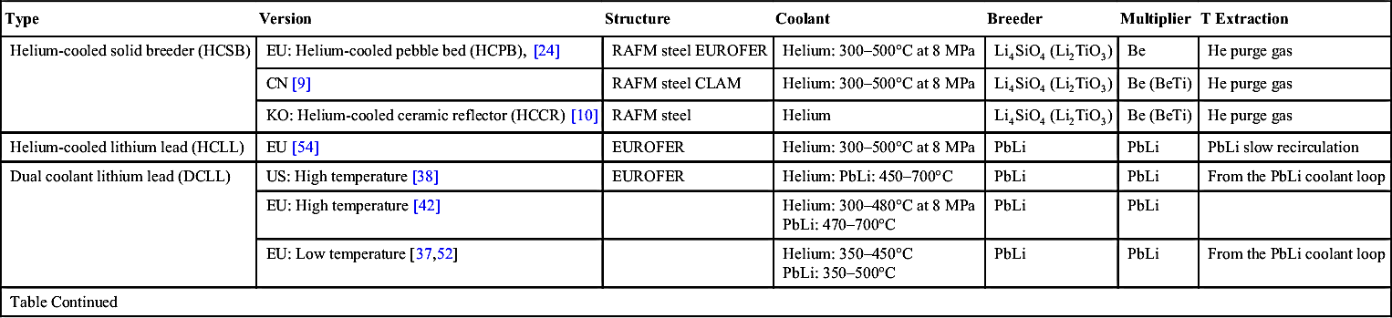
Several blanket concepts have been proposed worldwide to accomplish the described functions using different breeder materials, coolants, structural materials and cooling and tritium extraction scheme. Table 4.1 shows a not-exhaustive list of published concepts. Looking at the ITER Test Blanket Programme [21] and at recent reactor studies in Europe (EU) [17], China [57], Japan [44] and Korea [45], only a few of these concepts are presently considered as possible candidates for a DEMO and a first generation of fusion power reactors. In general, concepts for a DEMO consider the use of a Ferritic martensitic steel at reduced activation levels (RAFM); almost all the DEMO developers are considering in the design this class of materials that can be adopted in a temperature windows of about 300–550°C (maybe also extended to 600–650°C), has the potentiality to withstand irradiation damages of more than 70 dpa, can be recycled after irradiation after 100 years and can have a chance of licencing in 20–30 years for reactor application [26]. EUROFER is the RAFM steel under development in Europe, F82H in Japan, CLAM in China and similar materials are also under development in Korea and India.
Table 4.1
Major blanket concepts published
| Type | Version | Structure | Coolant | Breeder | Multiplier | T Extraction |
| Helium-cooled solid breeder (HCSB) | EU: Helium-cooled pebble bed (HCPB), [24] | RAFM steel EUROFER | Helium: 300–500°C at 8 MPa | Li4SiO4 (Li2TiO3) | Be | He purge gas |
| CN [9] | RAFM steel CLAM | Helium: 300–500°C at 8 MPa | Li4SiO4 (Li2TiO3) | Be (BeTi) | He purge gas | |
| KO: Helium-cooled ceramic reflector (HCCR) [10] | RAFM steel | Helium | Li4SiO4 (Li2TiO3) | Be (BeTi) | He purge gas | |
| Helium-cooled lithium lead (HCLL) | EU [54] | EUROFER | Helium: 300–500°C at 8 MPa | PbLi | PbLi | PbLi slow recirculation |
| Dual coolant lithium lead (DCLL) | US: High temperature [38] | EUROFER | Helium: PbLi: 450–700°C | PbLi | PbLi | From the PbLi coolant loop |
| EU: High temperature [42] | Helium: 300–480°C at 8 MPa PbLi: 470–700°C | PbLi | PbLi | |||
| EU: Low temperature [37,52] | Helium: 350–450°C PbLi: 350–500°C | PbLi | PbLi | From the PbLi coolant loop | ||
| Table Continued | ||||||
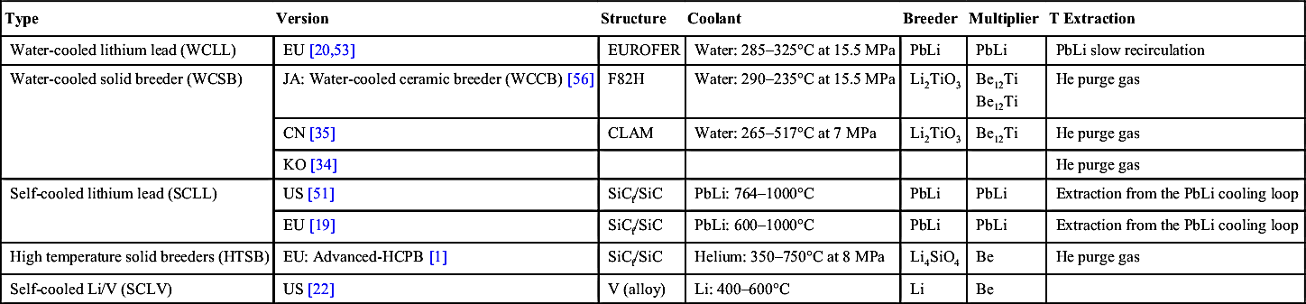
| Type | Version | Structure | Coolant | Breeder | Multiplier | T Extraction |
| Water-cooled lithium lead (WCLL) | EU [20,53] | EUROFER | Water: 285–325°C at 15.5 MPa | PbLi | PbLi | PbLi slow recirculation |
| Water-cooled solid breeder (WCSB) | JA: Water-cooled ceramic breeder (WCCB) [56] | F82H | Water: 290–235°C at 15.5 MPa | Li2TiO3 | Be12Ti Be12Ti | He purge gas |
| CN [35] | CLAM | Water: 265–517°C at 7 MPa | Li2TiO3 | Be12Ti | He purge gas | |
| KO [34] | He purge gas | |||||
| Self-cooled lithium lead (SCLL) | US [51] | SiCf/SiC | PbLi: 764–1000°C | PbLi | PbLi | Extraction from the PbLi cooling loop |
| EU [19] | SiCf/SiC | PbLi: 600–1000°C | PbLi | PbLi | Extraction from the PbLi cooling loop | |
| High temperature solid breeders (HTSB) | EU: Advanced-HCPB [1] | SiCf/SiC | Helium: 350–750°C at 8 MPa | Li4SiO4 | Be | He purge gas |
| Self-cooled Li/V (SCLV) | US [22] | V (alloy) | Li: 400–600°C | Li | Be |
A large number of these concepts is based on the solid breeder technology (Helium-Cooled or Water-Cooled Solid Breeder concepts, shortly HCSB and WCSB, as reported in the table). Typical solid breeders that are proposed for these blanket concepts include Li-oxide (Li2O) and ternary ceramics, like Li-orthosilicate (Li4SiO4), metatitanate (Li2TiO3), metazirconate (Li2ZrO3) or allumitate (LiAlO3). None of these is able to entirely fulfil a list of ideal requirements for breeder materials that encompasses very quick and easy tritium release, high mechanical resistance, compatibility with other materials (including water in the air moisture for out-of-reactor handling), high Li density, simple fabrication and recycling routes, etc. [30]. At present, the interest of the blanket designer has been focalised mainly around Li4SiO4 and Li2TiO3, accepting compromises, but giving priority to criteria of low activation, relatively high operational temperatures (up to ∼1000°C), sufficient tritium release capability to allow tritium inventory control (only 200–300 g tritium in the reactor breeder) and the feasibility of manufacturing and recycling routes. Li2TiO3 presents better characteristics compared with Li4SiO4, in terms of mechanical properties, chemical compatibility with water moisture and other breeding materials (like Be12Ti), and shows, however, a lower Li density that requires a higher 6Li enrichments for a comparable neutronic performance. To ensure sufficient tritium production, Be is added in the breeding zone due to its excellent neutron multiplication capability and the possibility of being used in solid form in a similar range of temperatures (at least up to 650–700°C).
Solid breeder blankets (with Be) present a simple way to produce and extract tritium; the solid material fills the blanket box that is formed by structures actively cooled for heat extraction; the breeder itself is not in contact with the coolant, but is purged by an independent low-pressure gas flow in order to extract the T produced. The boxes are typical double chambered components, where the high pressure coolant flows inside small channels (mainly realised in plate channels or tube bundles), while an independent low-pressure flow purge the breeder beds. The two chambers (see Fig. 4.1) are divided by thin walls for a very large surface. This results, however, in the permeation of tritium from the breeding beds to the coolant, which is a critical issue. Beryllium is required in a large amount (>3:1 volume ratio in comparison to the breeder) to ensure a sufficient tritium production due to an efficient neutron multiplication. Solid materials are sensitive to radiation and thermal damage, depleting in Li due to burn-up and cracking by radiation and thermal gradients. For these reasons, breeder and Be are used in these concepts mainly in form of a pebble bed with pebbles of diameters around 1 mm or less; pebble beds have relatively low thermal conductivity in the range of 1–5 W/m/K [47,61], but ensure a thermo-mechanical stability avoiding that properties can further deteriorate due to fragmentation. Usually the beds are arranged in thin layers of few cm. Fragmentation of pebbles also has to be minimised to avoid possible blockages of the purge flow with accumulation of tritium in parts of the blanket.

Figure 4.1 Schematic arrangements of breeder (ceramic with Be) and cooling in a solid breeder blanket represented in a vertical cross-section: ‘perpendicular’ (left) and ‘parallel’ (right) bed configuration.
The chemical element which are typically present in the ceramics and the beryllium materials (eg, Li, Si, Ti, Be, O) will be not strongly activated during the irradiation in the reactor (tritium as the goal of the breeding reaction is not considered here as activation product; tritium issues are considered in Section 4.3). However, the presence of typical impurities in the ore (eg, U in several original Be ore) or contamination in the production processes (eg, Al in ceramic pebbles) can jeopardise these excellent intrinsic properties. Control of impurities is the key to low-activation inventory levels in the reactor and so to allow a recycling of the breeders in reasonable time to reuse it in the reactor [29].
One of the most studied versions of this concept is the Helium-Cooled Pebble Bed (HCPB) developed since the 1990s by KIT [11] and recently under further development in the EU Power Plant Physics and Technology (PPPT) studies [5]. It uses helium at 300–500°C and a pressure of 8 MPa as coolant, EUROFER as structural material and Li4SiO4 and Be pebble beds in the breeding zone. The current design is shown in Fig. 4.2. The breeder zone is formed by a sandwich structure of horizontal alternating Be and ceramics beds separated by cooling plates. The ceramics beds are formed by pebbles of the diameter of 0.2–0.6 mm, a packing factor of about 63% and use Li enriched up to ∼50% in 6Li; the fabrication process for the pebbles is melting and spry. Beryllium is used in form of pebbles of 1 mm diameters and 63% of packing; reference fabrication process is the Rotating Electrode Method. Helium coolant is distributed by a manifold system arranged in a robust back plate; helium cools first the first wall and then the breeding zone. The beds are purged with a ∼0.1 MPa helium flow that transport the tritium to the extraction and removal system located outside the Vacuum Vessel; an addition of H2 (0.1%) helps per isotopic exchange the tritium release from the pebbles.
Water-cooled versions are also proposed in combination with solid breeders: in Japan, a WCSB concept is the reference concept for the ITER Test Blanket [16] and for the DEMO [56]. Water is used at pressure water reactor (PWR) conditions 290–335°C at 15.5 MPa. The purge mechanism of the breeder zone is similar to the other solid breeder concepts. Safety concerns in this case are for the possible accidental reaction between Be and steam with hydrogen production; for these concepts, alternatives to pure Be pebble are searched (in DEMO and FPP) in order to reduce the safety impact increasing the temperature margin to the exothermic reaction with steam (eg, use of beryllides; eg, Be12Ti compounds [59]). Hence, in the DEMO version, the beds are arranged in parallel as shown in Fig. 4.3; as ceramic breeder Li2TiO3 is proposed, fabricated with wet chemistry and sintering [25]. The beds are realised by mixing Li2TiO3 and Be12Ti that ensure better thermal (high thermal conductivities, high operational temperatures for Be) and mechanical properties of the beds. However, the presence of a larger amount of Ti (present now in the neutron multiplier) combined with the lower amount of Li density in Li2TiO3 aggravates the neutron performances that can be sufficient only with high 6Li enrichments and high packing factors (80% is considered in this study).

Liquid breeder concepts like the Helium-Cooled and the Water-Cooled Lithium Lead, shortly (HCLL and WCLL) concepts use the eutectic liquid metal PbLi (composition 15.8 at % Li with melting point at ∼235°C) as breeder; in these concepts, the cooling function is performed entirely (like in the solid breeder concepts) by an independent fluid, helium or water, respectively. PbLi circulates at low velocity (a few cm/s that corresponds to about 10 inventories of the blanket box moved in a day) so that no significant amount of heat is extracted by it. The PbLi recirculation aims only to transport the tritium outside the reactor for its extraction and for PbLi purification and chemical control. The recirculation of PbLi outside the reactor requires large loops that have to handle several thousands of tons of the liquid metals per hour; a recent assessment for the EU DEMO proposes eight loops located in the Tokamak Complex for a total of more than 5000-t inventory of PbLi and a recirculation capability between 0.6 and 1.6 t/s. A concern related to the use of such a liquid metal is the corrosion of the blanket steel structures, pipes and external components of the loop; a large amount of corrosion products could circulate with the risk of deposition in colder regions (or in magnetic fields acting as traps), causing blockage of flow or damage in moving components. Studies of compatibility with EUROFER and other RAFM steels [31] have identified possible critical corrosion rates in the temperature range above 470°C (depending also from the velocity). Hence, an effective control of corrosion products and a purification system of the PbLi have to be implemented in the design. Furthermore, this large amount of liquid metal will be strongly activated during the irradiation in the reactor. A particular concern is the production of volatile elements like Po, Hg or Ta as inherent components of the activation chain of Pb itself through the Bi formation [50]. Effective control of these end products or of the intermediate Bi formation has to be implemented. In addition, the corrosion products themselves can be a strong additional radiation source, increasing the necessity of purification loops, but aggravating operational safety concerns during maintenance.

Figure 4.3 WCCB Blanket concept as developed in the JA DEMO studies (courtesy JAEA) [56].
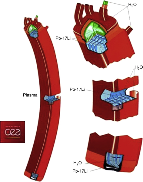
This technology was used for the WCLL that was developed in the European Union in the 1990s by CEA [20]; Fig. 4.4 shows the design proposed at that time. The blanket boxes are long RAFM steel structures containing a pool of PbLi (hydrostatic pressure around 1 MPa); the box also contains a bundle of vertical tubes submerged in the liquid metal in which the water coolant flows. Water conditions are compatible with the PWR fission technology as mentioned for the Japanese WCCB. Safety concerns are related to accidental conditions in which the coolant loops breaks inside the liquid metal pool, causing an immediate pressurisation of the box enhanced by chemical exothermic reaction between steam and PbLi [27]. The study of this reaction is one of the key R&D launched in the European DEMO Programme to assess the safety performance of this concept. A helium-cooled version of this concept (the HCLL) that avoids this issue was developed in CEA staring from 2004 [54]. Helium is used at the same conditions as described for the HCPB blanket concept.
Interesting among the concepts reported in Table 4.1 is also the Dual Coolant. Here the steel structure is cooled by helium, while the PbLi breeder is moved at higher velocity in order to extract a large part of the heat produced in it (50–60%). The version presently developed in the EU PPPT studies [52] is a low temperature version in which the PbLi temperatures are kept lower than 500°C to avoid compatibility issues with materials in the liquid metal loop and components. High temperature versions (PbLi up to 700°C) have been proposed in the US ARIES Programme [38] and in the EU PPCS [42] with the aim to increase the thermodynamic efficiency of the concepts as future solution for more advanced power plants. The concepts are based on flow-insert channels able to decouple electrically and thermally the PbLi flow in blanket from the RAFM walls. This allows to reach suitable velocities of the PbLi for heat extraction at reasonable magneto-hydrodynamic (MHD) pressure drops and to increase the bulk temperature of PbLi without endanger steel structures that are kept to lower temperatures (<550°C) by the complementary helium cooling.
The use of a liquid metal breeder, like Li or PbLi, or a molten salt, like FLiBe, that combines the function of breeder and coolant, opens the way to design more advanced blanket concepts, where unique loops provide both heat and tritium transport. This simplifies the layout of the blanket system, but complicates the technology of a loop that has to remove heat with large tritium inventories. Concepts of this kind are included in Table 4.1 but are not presently proposed as DEMO (short-term) solutions. They also require different structural materials; eg, silicon-carbide composite (SiCf/SiC) as ceramic material can be used to avoid MHD electrical coupling with liquid metals in the Self-Cooled Lithium Lead (SCLL) concept, or for very high temperature applications as in the High Temperature Solid Breeder (HTSB) blanket. Vanadium alloy is selected to contain fluid lithium in the Self-Cooled Lithium Vanadium (SCLV) concept.
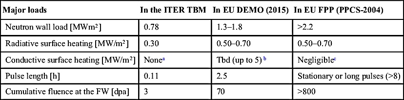
The key technologies for the breeding blanket have never been adopted in existing devices, and in ITER, the first burning fusion machine, they also will not be used. Instead, ITER will use a shielding blanket that is not suitable for tritium production and electricity generation. However, breeding blankets will be test in ITER in the form of relatively small objects (mock-ups of six different concepts of less than 1 m3 each located in three dedicated equatorial ports) in the framework of the Test Blanket Programme. This program constitutes an important milestone in the path of the development of a blanket system for a first generation of FPP. Here, mock-ups of leading blanket concepts like the HCSB, WCSB and HCLL (Ref. [4] presents an overview of the EU TBM systems) that are developed for testing in ITER conditions. Comparing (see Table 4.2) these conditions to what is expected in, eg, EU DEMO specifications [17], it is clear which major limitation this test will have; the most important is related to the cumulative neutron fluence that will allow only a few indications of the blanket behaviour under irradiation at the beginning of the life. In fact, irradiation levels at end of life as expected in DEMO will exceed of a factor of 20–50 the irradiation experienced by a TBM and even more for a future FPP. TBM FW will also be receded from the FW ideal line of the shielding blanket; this means that phenomena related to the plasma–wall interaction will be not investigated for the tested blanket component. There was (see also Refs. [2,48]) and is still present a big discussion about chances and limits of the blanket test in ITER. What is mostly agreed is that, taking into account the large differences in the key parameter as shown in Table 4.2, the success of the TBM mission will be dependent on the capability to develop modelling and calculation tools able to correctly design the TBM, to explain the results of the tests and then extrapolate them to the current DEMO design. Modelling and tools in the field of neutronics, MHD (in the case of liquid breeder blankets) or pebble bed thermo-mechanic (for solid breeder blankets), thermo-hydraulics, electromagnetic and T transport have to provide these capabilities combined with sophisticated measurement systems able to operate in an ITER fusion environment [8]. An important feature of the TBM test is the adoption of materials relevant for DEMO, eg, breeder and structural materials (EUROFER in case of the EU Programme). Finally, fabrication technologies validate for the TBMs can be used to build DEMO blanket components. In addition, the return of experience in fields like licencing and design guidelines and standard will produce important knowledge for the blanket development for DEMO (see Ref. [49]). The design itself of the TBM as a mock-up of a DEMO blanket is derived from blanket designs taken for the DEMO development in each country. In the European Union, the TBMs are based on a common blanket architecture of the HCPB and HCLL developed during a DEMO study in 2004 [3]. Presently, the design architecture is in rapidly change [5] to adapt the blanket concept to the specific DEMO 2015 requirements; however, these changes are not touching the major characteristic of both concepts in term of temperature, pressure and velocity of coolants and structural materials or breeders.
Table 4.2
Comparison of major loads in TBM and EU DEMO blanket
| Major loads | In the ITER TBM | In EU DEMO (2015) | In EU FPP (PPCS-2004) |
| Neutron wall load [MWm2] | 0.78 | 1.3–1.8 | >2.2 |
| Radiative surface heating [MW/m2] | 0.30 | 0.50–0.70 | 0.50–0.70 |
| Conductive surface heating [MW/m2] | Nonea | Tbd (up to 5)b | Negligiblec |
| Pulse length [h] | 0.11 | 2.5 | Stationary or long pulses (>8) |
| Cumulative fluence at the FW [dpa] | 3 | 70 | >800 |
As far as the second large in-vessel component, the divertor, is concerned, it is mostly excluded from the two main functions analysed in this section (at least in the more studied DEMO versions). The power deposited on the divertor, however, can be significant (up to 17% in some previous design [36]) and could be utilised as well for power generation, increasing the total efficiency of the fusion plant. The present difficulties in the design of solid targets suitable for exhaust particle fluxes of 10–20 MW/m2 make the thermo-hydraulic integration of such a circuit in a power generation system very challenging. The solution proposed for ITER and tentatively adopted as start configuration in many DEMO designs is based on the use of water at a low temperature (100–150°C in ITER). As this design is based on the use of a Cu-alloy (ie, CuZrCr) for the cooling tubes, the temperature range can be only slightly increased for DEMO (up to ∼200°C) without enter in operational temperatures not suitable for this material. Also, at this temperature there are many concerns about the lifetime of this component under neutron irradiation [58]. In comparison, the blankets are designed to work at a coolant temperature higher than 300°C to allow for efficient electrical energy production, so that separate coolant loops for the divertor systems have to be designed. As the heat removed by the divertor coolant loops cannot be integrated into the steam generators of the Rankine system, the only reasonable application is to preheat water coming from the condenser. Some present designs of DEMO are considering discharging almost entirely this heat in the plant heat rejection system avoiding the technical complications due to its integration.
Even if it can be technically possible to put breeding materials in the divertor (eg, in the cassette structure of an ITER-like divertor), this possibility has never been exploited in plant design. The reason is to avoid further complications and additional requirements (eg, T requirements) to a design of a component that has already so many critical issues to be solved. A possibility could be to attach target plates (and to realise exhaust pumping) directly on the blanket using then the cooling loop of it and the dedicated tritium extraction systems. This idea is partially followed in the PPPT DEMO design [17] where the dimensions of the divertor have been reduced drastically, and elements of this component (ie, buffers) are directly integrated in the blanket design.
4.2. Power extraction
4.2.1. Heating of plasma facing components
In-vessel systems are subjected to two main sources of heating, a volumetric source caused essentially by neutrons coming from the plasma core and a surface heating generated by the plasma edge and collected by the surfaces of the components facing the plasma. The first is due to the 80% of the fusion power that is associated to the kinetic energy of the neutrons (14 MeV) generated in the D-T reactions in the plasma which acts as 3D neutron source. The neutrons leave the plasma chamber without any interaction (the plasma density is too low for significant nuclear reaction rates). The 14-MeV neutrons have a spatial distribution which is almost axisymmetric and peaks at the equatorial plane; a reference toroidal surface enclosing the plasma core can be used to define the ‘neutron wall loading’ (nwl) which gives the energy flux of 14-MeV-neutron that passes this reference surface coming from the plasma neutron source. This quantity is expressed in terms of a power per area (MW/m2) and can be used to get a quantitative measure of the intensity of this energy flux in different parts of the plasma torus. Fig. 4.5 shows a typical poloidal profile for this calculated for a DEMO power reactor [46]. This quantity is calculated with respect to a reference surface that follows the FW contour; assuming a perfectly axial symmetric geometry of the plasma. The distribution can be represented in terms of an angle coordinate ψ defined in the vertical–radial plane z-r. This distribution is peaked at the equatorial plane of the plasma; in this example an average value of 1.3 MW/m2 is obtained with a maximum of 1.82 MW/m2 at the outboard equatorial plane (peak factor 1.4).
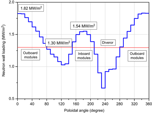
Figure 4.5 Poloidal Distribution of the Neutron First Wall Loading for a fusion power reactor of 2120 MW [46].
The neutrons leave the plasma chamber and interact with the matter of the in-vessel structures. Several different nuclear reactions take place which transfer in the end the kinetic energy of the neutrons to the nuclei of the interacting matter and thus heat the materials. The resulting power density profiles decrease with the depth depending on the composition of the involved materials. Typically, an exponential decrease is obtained as shown in Fig. 4.6 for the power density calculated for a solid breeder blanket (see Ref. [18]); radial profiles are shown the power density of the three different materials constituting the blanket structure of an HCPB blanket, namely RAFM, beryllium and the ceramics (Li4SiO4) pebble beds. The given power are of the order of tens W/cm3 (here they refer to a peak nwl of ∼1.5 MW/m2) with a maximum of ∼30 W/cm3 in the ceramics breeder.
These values of power density are not exceptional in nuclear technology; a typical value of operational power density in a modern light water reactor can reach in comparison peak values of more than 100 W/cm3. Hence, the removal of this heat is not particularly challenging, however, issues can arise due to the limitation of thermal properties of the materials. An example is the design of pebble beds in the solid breeder concepts. Referring to Fig. 4.1, it is evident that the critical design parameter is the height of the ceramic and beryllium beds. As the thermal conductivity of the pebble beds is poor (eg, ∼1 W/m/K for the monodisperse Li4SiO4 and 3–4 W/m/K for the mono-sized Be pebble bed used in the HCPB design) limitation can arise in this parameters to avoid large temperatures in the middle of the beds. For the proposed thin bed geometry, a heat density production of about 30 MW/m3 in Li4SiO4 require a maximum thickness of only ∼12 mm if a limitation of the max temperature of 920°C is required in the beds.
In liquid breeder concepts like the WCLL or HCLL where the PbLi is used in quasi stagnant conditions, the thermal situation in the breeding zone is similar as the thermal exchange is dictated mostly by the conductivity of the breeder; the better thermal conductivity of PbLi (∼12 W/m/K), however, helps the design allowing thicker breeder layers. In any case limitations arise in the max temperature of the PbLi at the contact with the steel structure that is translated again into a limitation of the maximum cross dimensions of the PbLi flow channel. In all these concepts (HCPB, HCLL), the cooling of the bed results by external cooling plate in which the coolant (helium for these concepts) is flowing in small channels. Coolant conditions in the breeding zone are not critical, heat transfer coefficients around 2000 W/m2/K are sufficient and achievable with helium velocity under 30 m/s associated with moderated pressure drops.
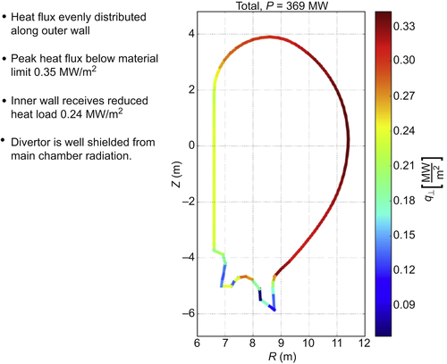
The second thermal source is localised at the surface of the components facing the plasma (the first wall). This power derives from the remaining 20% D-T fusion power that is associated to the alpha particles with the addition of the heating directly injected into the plasma (ie, heating and current driver systems). Several cascade reactions happen in the core and the edge of the plasma causing a direct radiation of short wave electromagnetic radiation (eg, synchrotron, Bremsstrahlung, line radiation) and high energetic particles (electrons and ions) that are absorbed in few μm of the First wall surface. Fig. 4.7 shows an estimation of the direct radiation of the core that was done for the EU DEMO design; loads up to 0.4 MW/m2 are expected on the surfaces of blanket and divertor components. The uncertainties associated with this calculated distribution are not well known.
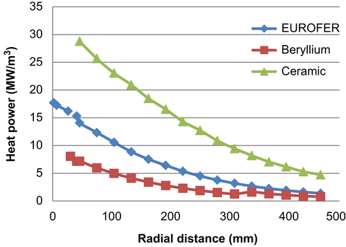
Figure 4.6 Radial volumetric heat power distribution on different materials of the solid breeder blanket HCPB [18].
The remaining part of this ‘exhaust’ power is released in form of electrons and ions that are trapped by the magnetic fields; they products a strong ‘plasma flux’ that follows the external plasma contour along the helical magnetic lines. In the divertor configuration (like in ITER and as expected for the DEMO reactors) this plasma flux is mostly directed in toroidal direction with a poloidal component that directs it to the divertor plates. This flux can be more than 100 MW/m2 at few centimetres from the separatrix, decreasing to 10 MW/m2 at about 15 cm (see Fig. 4.8 referring to ITER); this plasma flux is responsible for the concentrate heat on the divertor plates that have to be designed to sustain heat fluxes of more than 10 MW/m2.
This heat flux is concentrated on the divertor region where solid targets are designed to impact directly the magnetic line diverted outside the core region. The resulting heat flux is a major (maybe the major) concern in the design of a fusion power plant and it constitutes one of the most technological challenges to realise the fusion reactor. Solutions to remove this flux have been proposed for ITER. The reference configuration of the ITER divertor has been developed at the end of the 1990s by modelling the behaviour of the divertor plasma for different target geometries and with validation tests in JET [28]. The ITER divertor configuration is a vertical target/baffle with an open private flux region and a dome below the X-point. The vertical target is inclined so as to intercept the magnetic field lines of the separatrix at an acute angle; this allows a reduction factor of 10 on the original flux. This reduction is based on an optimum control of the geometrical parameters. The design of the Plasma-Facing Unit of the target is particularly challenging; the ITER design requires removing 10 MW/m2 as stationary load and up to 20 MW/m2 in slow transients. The heat transfer components use the mono-block configuration (see Fig. 4.9); a central tube of copper alloy (CuCrZr) is surrounded by W-blocks of dimension of about 28 × 28 × 12 mm3. The Cu-alloy pipe is a pressure component able to sustain water at about 4 MPa, 100–150°C and ∼10 m/s [39]. A compliant layer to accommodate differential expansion mismatch of casted Cu is realised between pipes and mono-block. To increase the heat transfer performance of water, a swirl tape is inserted in the tube, causing a spiral movement of water in the channel; it enhances the critical heat flux (CHF) limits providing a ∼1.5 margin on 20 MW/m2 slow transients. The W-mono-block provides protection of the pipes versus plasma interaction; here about 8-mm-thickness is proposed at the plasma side as a compromise between limiting surface temperature and the necessity to cope with plasma erosion (to provide a sacrificial layer to increase the lifetime of the component).
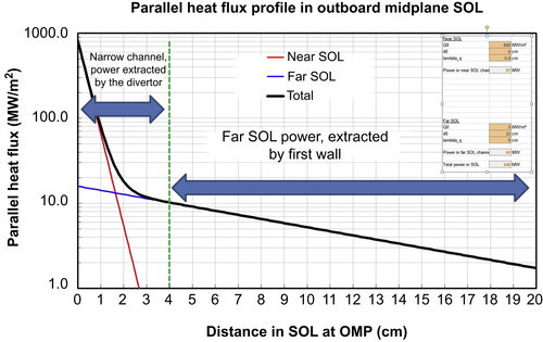
Figure 4.8 Plasma heat flux density parallel to the magnetic field line, across the outboard scrape-off layer in an ITER-size and power tokamak.

The proposed solution has a good chance to work in the ITER environment, but is it able to survive in a real fusion reactor? The major difference (starting from DEMO) will be the higher level of neutron irradiation; in the PPPT DEMO, the divertor has been designed for a maximum neutron damage of 5 dpa that corresponds to five calendar years, but in an FPP (at 75% of availability) this would correspond on only 1 year. Hence, for an FPP, the neutron flux survival of a divertor should reach about 20 dpa to be compatible with high plant availability.
A completely different approach can be illustrated with the helium divertor developed in KIT [43]. Here the coolant helium is used at a high temperature (600–700°C) in order to integrate the heat directly in the power generation system. In addition, structural materials are selected (like W) with the potentiality to withstand high neutron damage and with high thermo-mechanic performances in order to sustain the high thermal fluxes. However, data for W and W-alloy under irradiation are scarce, but the rapid increase of embrittlement under irradiation has been already observed in some samples for temperatures below 800°C.
For the moment, the major R&D in this field is focalised in two directions: to better understand the physical phenomena at the plasma edge in order to find configurations able to reduce the thermal loading (eg, super X, snow-flakes), and to improve materials properties in order to operate prototypically under irradiation.
As described above, the plasma flux is causing one of the strongest heat loads in the device. However, this load due to the plasma flux is not only challenging to the divertor target, but it can affect the thermal loading of all the FW. The prevision of the distribution of this power on the blanket first wall is affect by large uncertainties. An example of this is in ITER; there the large uncertainties in the FW thermal loads have been faced design the first wall of ITER according to large protective factors [40]; this means that the cooling is designed in the whole wall for the maximum expected thermal loads including start-up transients. Hence, the entire wall is designed for 2 up to 5 MW/m2.
In the design of the breeding blanket for DEMO, this approach has scarce chances to work. First of all, if the maximum value of the heat flux exceeds values of 1–1.5 MW/m2, no present materials are available that can sustain neutron damage of more than 20 dpa (this is the minimum design value for blanket components with EUROFER, but the target is at least 50 dpa, also for a second set of blanket in DEMO) with high thermal performances. Materials suitable for blanket application, like the class of RAFM steel described in 4.1, have thermo-mechanic properties (eg, only ∼30 W/m/K thermal conductivity) that are too low for such high thermal fluxes. Second, if a shaped first wall is necessary (like in ITER), the uncertainties of the power distribution will be very high; geometrical tolerance in blanket assembly, movements in operation related to thermal expansion and uncertainties in plasma control alignment will contribute to these uncertainties.
4.2.2. Primary heat transfer system
Taking into account the characteristic of the thermal sources (volumetric and surface), the general hydraulic layout of the Primary Heat Transfer System (PHTS) that cools the in-vessel components is very demanding. First of all, the already stated difficulties in the integration of coolant loops serving the divertor and the blanket systems demand the use of different lops at different coolant conditions. In the HCPB, the helium cooling scheme is organised with parallel channels fed by long poloidal channels connected to the ex-vessel systems. Fig. 4.10 shows this scheme for a configuration in which also the First Wall cooling is fully integrated. Coolant at 300°C is entering from the top of the segment and is distributed by large poloidal manifold to the FW in toroidal-radial channels. At the end it is collected by poloidal manifolds that distribute the coolant in the breeder zone. The scheme foresees the integration of two (almost symmetrical) independent coolant loops so that in case of ex-vessel LOCA, at least one of them remain intact and can be used to mitigate the thermal transient and remove in the long period the afterheat. The cooling scheme of the box is based on hundreds of parallel channels; the issues are related to the accurate distribution of the mass flow in them and in the related pressure drops. It is clear that the most loaded channels (‘hot channel’) will dictate the performance of all the system, as the pressure drop regulation have to ensure the same pressure drops in all the channels at different mass flow to cope with different flux distribution. Hence, two main concerns are: the high thermal load of the hot channels (too high peak factors) will produce a bad thermo-hydraulic behaviour for all the blanket segments, and the uncertainties will produce a too large difference between an average heat flux and a maximum heat flux that can be expected.

Up to know the better design solutions for the blanket has been found considering an FW fully integrated in the mechanical a hydraulic design of the blanket box. This is a simple and efficient solution that facilitates the fulfilment of several requirements, from TBR to structural-mechanics. It works for relatively low surface loads (under 0.5–1.0 MW/m2, depending on the used coolant) and uncertainties in the range of ±15%. If the conditions are not available other design illustrated in Fig. 4.11(b) and (c) have to be adopted, namely a thermo-hydraulically decoupled one (b) that can be useful in case of large uncertainties to not disrupt the design of other parts. The fully decoupled solution (c) could be adopted to reduce thermal and EM loads or if the lifetime of the FW components falls below the limits prescribed for the remaining blanket (eg, for the use of other structural materials than EUROFER) requiring a local replacement.
The WCLL and the WCSB follow almost the thermal design and limitation proposed for the corresponding helium-cooled concepts. The main difference is due to the thermo-hydraulic condition of water coolant. If PWR conditions are used (285–325°C at 15.5 MPa), the temperatures are lower giving additional margin in the steel temperature range and the temperature gradient are smaller, but pressure is higher requiring thicker channels walls than Helium concepts for comparable geometries.
Water has excellent coolant performances, but presents issues in the detritiation and in the compatibility with materials in operational and accidental conditions (eg, reaction with breeder or multipliers with possible production of H); helium doesn't performs as well as coolant, but presents the better compatibility with materials and can be used also at very high operational temperatures. Liquid metals also have been proposed as coolant. The issue that limits their performances is the presence of strong magnetic fields; high pressure drop and turbulence suppression make their use very restricted in particular in combination of electrical conducting structures. Hence, molten salts have been proposed as alternative for their low electrical conductivity, but application range, corrosion and chemical control are limiting issues.
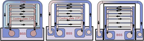
Figure 4.11 Possible design options for the blanket FW: integrated design (left), hydraulic decoupled (mid), fully decoupled (right).
About the general organisation of the coolant systems, the fusion reactor uses a PHTS for blanket cooling in form of a closed loop. In a simplified version, it will exchange heat directly to a secondary system that is used for electrical power production. This configuration is dictated by concern of possible (and almost unavoidable) contamination of the PHTS with tritium produced in the blankets (see Section 4.3). It suggests to avoiding a direct employment of the coolant of the PHTS in the turbine and in particular with Rankine systems. Designs have been proposed also with a third intermediate loops (eg, with NaK) in order to avoid tritium permeation especially in steam generators. Furthermore, from safety point of view and also from economics, the PHTS should be designed modular so that the sizes of the components are smaller and do not require much space in the tokamak confinement. In case of damage of the first wall or an in blanket leakage, the pressure limitation is much easier to handle, since only one or two segments are affected. This allows to reducing the dimension of an expansion volume to keep the pressure increase in the vacuum vessel below the design limits (0.2 MPa in ITER).
4.2.3. Balance of plant
A novel part to fusion machines for DEMO and FPP design is the necessity to transfer the thermal energy extracted from the plasma via first wall, breeding blanket and divertor and/or other heat sources to a commercial power conversion system (PCS); furthermore, the Balance of Plant (BOP) is responsible to provide in house power and cooling capabilities to all DEMO systems. At the end, an efficient, safe and economic reliable BOP is responsible for the power output and hence for the acceptability of DEMO as a (first of a kind) FOAK for industry.
Power conversion systems based on steam cycles are presently split into types: highly developed high temperature PCS and low temperature (∼325°C) systems, the latter are dedicated to water-cooled nuclear reactors, since the temperature limit comes for those heat transfer conditions in the reactor (eg, PWR conditions). For conventional power plant and generation IV reactors, advanced power conversion systems increase the efficiency by increasing the turbine inlet to 600°C and more as indicated in Fig. 4.12. A typical layout for that temperature, as has been developed by Alsthom for CEA, is given in Fig. 4.13; here a heat source at ∼500°C (as coming from an HCPB or HCLL blanket concept) can be used achieving gross efficiency of about 42%.
Other solutions are in discussion such as Brayton cycle or Brayton with supercritical CO2. However, both are presently in an early stage of investigations, only small loops are built (Sandia Labs: 20 MWth) or in design. So for DEMO a reliable well proven and qualified technology is selected to reduce uncertainties. Steam cycles are excellent up to 700°C depending on material and costs, above 750°C Brayton cycles become of interest. For a 500-MWe PCS, the overall efficiency is 42% while a supercritical CO2 cycle for the same conditions only achieves app. 38%.
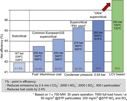
Figure 4.12 Development of steam turbines [60].

Figure 4.13 Typical industrial steam cycle (Rankine) layout of a 500°C PCS designed for 500 MWe [33].
A further issue related to the heat extraction and exploitation is the operational regime. Intrinsically, a tokamak reactor is a pulsed machine, but steady state or very long pulse operation are possible using not induction current drive systems. These systems require large recirculation currents and at the present the physical basis are not very well established. For this reason, eg, in the current EU PPPT relatively short pulses (2.5 h) are considered for the plant layout. This implies a stop of the machine to recover magnetic fields and vacuum that can be of more than 30 min. This possible regime add additional issues at the power extraction; first is induced strong mechanical loads in term of fatigue, second make the lay-out of the power pulse system very challenging. PCS, which are able to operate and withstand such frequent transients, are not available at the market, especially for the short distance between ramp-down and ramp-up. Furthermore, to start the plasma operation, a large amount of energy is required for magnet loading and additional plasma heating. To overcome these harsh conditions and to maintain the proposed lifetime, a thermal buffer (energy storage system, in short EES) has been proposed, to be implemented in an intermediate heat transport and storage system (IHTS) [23]. It allows decoupling of the pulsed heat production in the DEMO reactor and allows operating the PCS in a stationary way.
In the PPPT studies, the IHTS is a low-pressure system using a heat transfer fluid with an application range up to 500°C. Actually, the proven solar salt from concentrating solar power is proposed (NaNO3-KNO3), but for future power uprates of an FPP, the design can also be used for liquid metals. The PHTS transfers the heat in an intermediate heat exchanger (IHX). From the IHX the heat is transported using the low pressure heat transfer fluid out of the tokamak building to the PCS-Building, where the power train and the auxiliary systems are located. The IHTS starts with the collector, a ring pipe inside the confinement and exits it at one position. The IHTS is a self-draining system, so that in case of an outage, the whole amount is stored in the well thermal isolated ESS. Bubelis and Hering [7] presents the layout of two complex BOP systems for water and helium PHTS using the IHTS developed; the simulations have been done with the industrial power plant system EBSILON [6]. The water option (see Fig. 4.14) refers to light water reactor technology of the WCLL. The Breeding Blanket is given on the left side of the figure, here simplified into one loop only. In the centre, the IHTS with a two tank ESS is given and on the right side a very detailed PCS. As can be seen here, power from the divertor and the vacuum vessel cooling is integrated into the feedwater heating chain, allowing a better usage of the available heat sources and reducing steam extraction from the turbine. An analogous system can be developed with helium for the HCPB and HCLL concepts, where the higher temperature span (200 K in comparison to only 40 K for water) allows a strong reduction of the dimensions of the involved components.
Finally, DEMO should demonstrate not only that it can produce power, but that the power can be controlled to follow grid or market needs. Since the plasma output cannot be varied to more than 10% without affecting stability, the necessary flexibility could be achieved with an ESS. The dimension of the ESS allows a flexible optimisation of DEMO and later an FPP to the needs of the customer. Even if an FPP with a steady-state plasma is at the market, the need to control the output will require an ESS, however much smaller as in the pulsed configuration. Other possible countermeasures, such as additional fossil burners or gas turbine face the same problems, frequent thermal and dynamic transients as well as additional costs for operation and maintenance.

Figure 4.14 DEMO BoP scheme for water-cooled blanket concept with the integrated intermediate heat storage loop as modelled by KIT [7].
4.3. Tritium production
During a flat-top burning phase, the usage of tritium in the D-T reaction has to be compensated by the constant injection of new tritium into the plasma. Usually the injection rate has to be much larger than the actual tritium burning rate due to the He produced that impedes the D-T reaction to proceed. Therefore, large amounts of tritium have to recirculate through the vacuum pumping, the fuel cycle and the fuel injection systems (in ITER, the tritium burn-up fraction is only 0.3% and will be expected 1.5% in DEMO). As already discussed in the introduction, in a fusion power plant, tritium has to be produced entirely by the blankets; it is then extracted from the breeding materials, separated from tritium carriers, impurities and other hydrogen isotopes (H and D), and integrated in the fuel cycle to finally be injected into the plasma.
Fig. 4.15 shows schematically the cycle of tritium in a fusion reactor. A first stored tritium amount (several kilograms) constitutes the starting inventory for the plant (in ‘tritium storage’). It should provide sufficient tritium for the first days as soon as the cycle arrives in a stationary condition. The tritium and deuterium are injected in the plasma. As already mentioned only a part of them will burn, but the rest will abandon the plasma and will be extracted by the pumping systems, reprocessed and again sent to the storage to again feed the injection system. This constitutes the so-called ‘inner fuel cycle’. The ‘outer fuel cycle’ starts with the tritium production in blanket under neutron reaction; this tritium is collected and processed to remove it from the different carriers (eg, purge flow, liquid breeder, coolant). Finally it is delivered to the separation system to be integrated in the inner cycle. Impurities are removed from the processing units and sent to the waste management system.
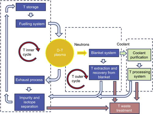
Tritium inventories can be built in the different stages of the cycle depending on the time constants of the different processes and loops (eg, diffusion processes in the breeding materials) or by trapping mechanisms (eg, in metal). A general issue of an FPP is to minimise the tritium inventory in the different parts of the reactor (in the VV as well in the tritium plant); this is a safety concern related to possible mobilisation of these inventories in case of an accident and its release in the environment. For this reason, the tritium cycles must be optimised to reduce time constants in the tritium processes and then minimise the inventories (see Ref. [12] for more details).
The production of tritium is ensured by the presence of lithium compounds in the blanket that can react with the neutrons produced by the thermonuclear reaction. 6Li and 7Li produce a tritium atom for each neutron absorbed, and in the case of 7Li, a further neutron is released in the reaction and available for further reactions. Taking into account that not all neutrons produced in the fusion reaction will react with Li in the blanket and that other materials will absorb a large amount of them, a surplus of neutrons generated in multiplying reactions is indispensable to maintain a positive tritium balance necessary to attain tritium self-sufficiency. The ratio between the tritium produced in the blankets and the tritium consumed in the fusion reactions in the plasma (that coincides with the number of neutrons emitted in the thermonuclear D-T reaction) is called Tritium Breeding Ratio (TBR). The TBR must be greater than one to compensate the T burnt in the plasma. How large the TBR should actually be during the lifetime of the FPP is dependent on the ‘dynamics’ of the entire fuel cycle for the D-T plant, as shown in Fig. 4.13. It involves time constants and efficiencies of many subsystems and has to take into account possible losses of tritium in the different parts of the process and tritium trapping in the materials (see Refs. [55] and [15] for more details on the tritium balances for ensuring self-sufficiency). In addition several other requirements that have to be accounted for, such as duplication time (time necessary to produce the tritium amount necessary to start a new FPP) and storage capabilities; also the natural decay of tritium (a half-life of 12.3 years in the machine has to be considered).
The TBR is a characteristic of the used blanket system and it is determined essentially by the geometry and material composition of the blankets; it can change during the lifetime of blanket components as effect of the Li burn-up and nuclear transmutations. Theoretically, lithium with a natural isotopic composition is capable to provide sufficient TBR, assuming however pure lithium (ie, Li fluid metal) in combination with blanket structural materials with a very low neutron absorption such as vanadium or SiC. A V-Li blanket concept was earlier studied in the US and Russia but almost abandoned in recent studies (see Table 4.1).
To improve the neutron balance, a neutron multiplier is added to the breeder. Such a multiplier material provides ‘neutron multiplication’ through (n, 2n) reactions. Effective multipliers are, first of all, Be and, second Pb. In this case, 7Li is not required to produce tritium and a better neutron economy is achieved by increasing the fraction of 6Li beyond the natural atomic abundance of 7.5%. Enrichments of 50% up to 90% in 6Li may be necessary to compensate parasitic neutron absorptions in additional materials in the breeding zone. The HCPB design described in Section 4.1 is a good example of this technology. The spectrum is relatively well moderated (the neutron multiplier Be is also a good neutron moderator) so that attention must be paid on any material in the blanket that can absorb neutrons. An example is the EUROFER itself that efficiently absorbs neutron at energies of a few tens of keV and below. As the design of a blanket breeding zone is a compromise, among the tritium breeding capability, the thermo-hydraulic design for heat extraction and structural-mechanical design, the amount of steel must be reduced as much as possible while still achieving the targets of mechanical stability (eg, against pressure, thermal and EM loads).
A control of the TBR level during the life of the reactor can simplify the goal to keep the inventory of tritium as low as possible in the storage system; it could allow reducing the tritium production if the tritium level increases in the system (and the contrary). This control can be realised in a simple way only for liquid breeder blankets. Here, the external circulation of the breeder allows a chemical control of the liquid composition. This includes the possibility to tailor the level of 6Li enrichment in the breeder, according to the requirements. A similar possibility doesn't exist in solid breeder concepts where the design should primarily ensure the correct level of TBR necessary for the entire lifetime of the blanket. Other possibilities (like the inclusion of a neutron poison or control roads) are imaginable, but they have never been proposed in the published blanket designs.
The tritium generated inside the breeder has to be efficiently extracted. In solid breeders tritium is primarily formed as atom inside the ceramic grid; it has to reach the grain and pebble external boundary, to recombine as molecule to be extracted by the purge gas. The process of extraction from the solid material is complex and different phenomena concur and delay the tritium release. For design purpose a quantity is used to characterise this process, the so-called Tritium Residence Time (TRT); it can be defined as the time constant associated to the release process from the pebble and can be determined experimentally in reactor from thermal transient during irradiation [32]. It is strongly correlated to the temperature of the material; correlations gained in experiment show an exponential dependence with the temperature. Other dependencies are from material, microstructure and composition and from purge gas chemistry (addition of H2 or H2O helps to extract tritium per isotopic exchange [41]). Typical values measured for Li4SiO4 are ∼1 day at 350°C and less than 1 h at 600°C in a reference purge flow of 0.1 MPa of He with 0.1% H2. As noted before, large time constants are responsible of large inventories; inventories of 200–300 g of tritium for an amount of ceramic of about 100 t have been calculated in reactor assessments.
As soon as the tritium is extracted from the solid materials, the helium purge-gas transports the tritium outside of the reactor where it is removed from the He carrier and concentrated before being sent into the fuel cycle. Different processes are under investigation to treat the purge gas, and a selection of the most efficient technologies has to be done. The reference process [14] adopts batch cryogenic technology (with molecular sieves and cold traps operating in alternating adsorption and recovery regimes), but more advanced processes relying on membrane, and catalytic membrane reactor technologies are under evaluation to operate in a continuous regime, with a lower time constant and energy saving.
The extraction for liquid breeders is different; eg, in PbLi, tritium is generated during the presence of the liquid metal in the reactor and then is recirculated outside the reactor. Hence, the PbLi is used as a carrier to transport tritium outside of the reactor for its extraction. During its flow inside the blanket, tritium is generated in atomic form in the liquid; its movement is dictated by the movement of the liquid that flow in a complex MHD environment and by diffusion leaded by concentration gradients. Tritium can be trapped in He bubbles (He is formed in PbLi by side nuclear reaction involving Li, in fact each Li + n reaction produces 1 T and one He atoms). Several processes are under investigation for an efficient tritium extraction; they include Gas Liquid Contactors (GLC), Permeation Against Vacuum (PAV) or Vacuum Sieve Tray (VST) methods. Again, the aim of the current investigation is to provide efficient, safety, reliable and economic processes. The subsequent phase of concentration is simple and in case of PAV practically only T (with low H, D impurities) is extracted and can be delivered directly to the fuel cycle.
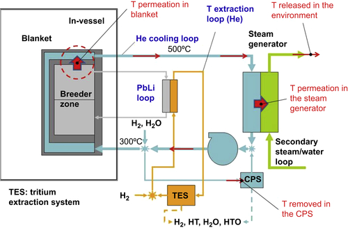
In considering technical challenges related to the tritium production, the several safety concerns that are related to these topics must be mentioned. As already mentioned, the limits of inventories have to be strictly controlled. Usually only a few kilograms of tritium are allowed in VV or in the fuel cycle to avoid a potential large release requiring evacuation of population. Tritium can constitute a risk during normal operation due to the possibility of being released in the environment. The limits imposed to ITER and tentatively assumed also for a future power plant are considering not more than 1 g per year released, which means for a 2-GW fusion power plan with an availability of 75% (with a production/consumption of ∼84 kg of T in a years) only a 10−5 fraction of the tritium handled in the facility. The major possible of tritium escaping from the plant is through the coolant system, eg, in the HCLL, the proximity in blanket of coolant and PbLi loop cannot exclude permeation of tritium in the coolant [13]. This tritium can reach the steam generator and then permeate/leak in the secondary loop. Several protections are designed to avoid it, including Coolant Purification Systems (CPS) acting in the PHTS to control the level of contamination of the coolant (see Fig. 4.16). In addition, permeation barriers or chemical control are proposed to reduce the quantity of tritium moved per permeation in the blanket, in the steam generator, or additional intermediates loops, as already mentioned in Section 4.2.
Safety concern will also include waste management of tritium-contaminated components and materials.
..................Content has been hidden....................
You can't read the all page of ebook, please click here login for view all page.