
15
Large helical device
Abstract
The Large Helical Device (LHD) is the world’s largest helical device based on the “heliotron” concept, which consists of two continuous intertwined helical toroidal coils. The major goal of the LHD experiments is to demonstrate the high performance of net current-free plasma in a reactor-relevant plasma regime. The construction and the succeeding 17-year operation of LHD have shown its intrinsic advantage of stable steady-state plasma operation and its attractive features of plasma performance. The LHD has contributed greatly to the development of engineering basis and the systematic understanding of net current-free plasma physics. The project is a big step for helical fusion plant.
Keywords
Helical system; Heliotron; Net current-free plasma; Nuclear fusion15.1. Mission and goals of the LHD project
The Large Helical Device (LHD) is the world's largest helical device based on the “heliotron” concept, which was developed at Kyoto University [1]. In the 1980s the three large tokamaks (JET, TFTR, and JT-60) achieved fruitful results extending plasma parameters to the reactor relevant level, but they each presented issues for stable steady-state operation (current drive, major disruption, upper density limit, and others) of high-performance plasma. It was well known that the mere external winding coils can produce a confining magnetic field structure in steady state (stellarator). However, such a system was considered to suffer from poor plasma confinement due to the existence of fine magnetic field ripples (helical ripples) in addition to the toroidal ripple as a toroidal device. However, the good results from the Heliotron-E [2] and the Wendelstein 7-A [3] revised these concepts as a steady-state fusion device, and the verification by constructing a larger helical device was sought (Table 15.1).
The LHD project started in 1989 as a joint-university program of fusion research in Japan, and was planned as an alternative program that clarified the potential of prospecting a steady-state toroidal magnetic fusion power plant. Therefore one of the objectives of the LHD project is to produce a high-performance plasma that can be extrapolated to the fusion power plant, such as the fusion triple product nτT ∼1 × 10²⁰ keV∗s∗m−3, volume averaged β of ∼5%, and good confinement of high-energy ions. The other objective is to develop engineering bases for a design helical fusion power plant. Among these objectives, the manufacturing of large helical superconducting magnets was a major issue because the LHD was designed to be equipped full superconducting magnetic coil system in order to demonstrate steady-state operation [4].
15.2. Design concept of LHD
The LHD was designed based on the heliotron concept, which has a magnetic coil system consisting of two continuous intertwined helical toroidal coils and three pairs of circular poloidal coils (Fig. 15.1). The poloidal coils cancel the vertical fields produced by the helical coils, and the residual dipole and quadrupole fields control the position of the magnetic axis and the shape (ellipticity) of the magnetic flux surface, respectively. The design of the magnetic coil system was made in this way so to optimize the three quantities: high-beta MHD stability, good high-energy particle confinement, and clear helical divertor structure. There are several free parameters in designing the helical system. The advantage of the two-pole (ℓ = 2) helical system is its inherent clear divertor structure. Then the toroidal pitch number p was determined as 10 (in combination with “pitch parameter” γc = pac/ℓRc as a design parameter, where ac and Rc are minor and major radiuses of the helical coil [5]) in order to maintain enough clearance between the plasma and the wall. The other design parameter is the pitch modulation of helical coil winding α (θ = (p/ℓ) ϕ + α sin{(p/ℓ) ϕ}, where θ and ϕ are the poloidal angle and the toroidal angle, respectively [6]), and α = +0.1 was chosen for better high-energy particle confinement.
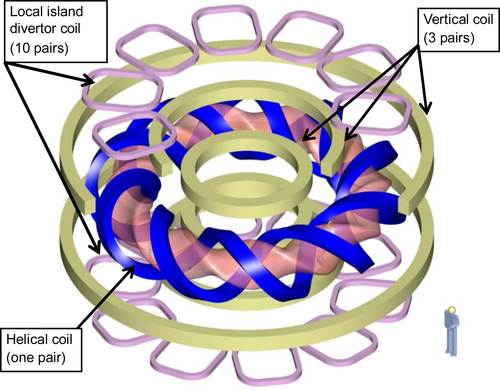
Figure 15.1 Magnetic coil system of LHD. It consists of a pair of helical coils and three pairs of circular poloidal coils. Additional set of local island divertor (LID) coils (made of normal conductors) are also installed.
The LHD has been installed additionally with the local island divertor (LID). Coils which can superpose a resonant magnetic field, and make large magnetic islands at the resonant surface having m = 1 and n = 1, or m = 2 and n = 1, where m and n are the poloidal number and the toroidal mode number, respectively. The LID coils are made of normal conductors.
The produced magnetic field structure of LHD (a Poincare plot on the poloidal cross section) is shown in Fig. 15.2. The region where closed magnetic surfaces are formed is covered with a thick “ergodic region” where the magnetic field lines are open. That is, they are connected directly to the wall of the vacuum chamber. However the length of magnetic field line to the wall (connection length) are rather long in the LHD (see the lower trace of connection length in the figure). Considering that the velocity of 100 eV proton is 105 m/s, it takes a few ms for ions to reach the wall. Therefore, there exists low-density plasma in the ergodic region even outside of the last closed flux surface (LCFS), which affects the performance of LHD plasma such as impurity transport (shielding) for example. The other feature is its clear four helical divertor field lines although the two separatrixes are surrounded by the thick ergodic layer. The long connection lengths to the wall of these diverter field lines means that the vertical transport should be considered when the plasma flows along the divertor field line. This situation is different from tokamak where the connection lengths are rather short.

Figure 15.2 The upper shows a Poincare plot of magnetic field lines. The lower shows a distribution of connection length from the last closed flux surface to the wall through separatrix.
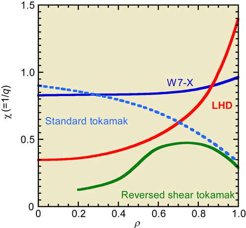
Figure 15.3 Radial profile of rotational transform of the LHD. Comparison is made with those of tokamaks and advanced stellarator (Wendelstein 7-X).
Inside the LCFS, clear ellipsoidal magnetic surfaces are generated, which rotate along the toroidal direction. The specific feature of heliotron configuration is its large rotational transform at the edge region (Fig. 15.3). In a heliotron, the MHD activities are stabilized by its large magnetic shear at the edge, and by the magnetic well in the center. The magnetic well is spontaneously formed by the Shafranov shift due to finite β effect. It is noted that the spatial profile of rotational transform (ι/2π = 1/q, where q is a safety factor) is opposite to that of tokamak (Fig. 15.3). It is also noted that the “advanced stellarator” Wendelstein 7-X [7] has very weak magnetic shear but a magnetic well to stabilize MHD activities avoiding the resonant surface of q = 1 inside the confinement region carefully (Fig. 15.3).
15.3. Plasma production and heating
15.3.1. Electron cyclotron resonance heating
Since helical systems do not need a net toroidal current, the initiation of plasma should be carried out by other than Ohmic heating. The most conventional method of plasma production is the electron cyclotron resonant heating (ECRH). A standard operating magnetic field strength of the LHD is 2.75 T at the center of the plasma, and the corresponding fundamental electron cyclotron resonance frequency is 78 GHz. Development of high-power gyrotrons of this frequency range was one of the engineering issues of the LHD project. Thanks to the remarkable progress in the development of gyrotrons since the 1990s, a steady-state gyrotron of 1-MW output is now available [8]. One of the specific features of ECRH is that the wave can be converged on the small area of around 1–2 cm in diameter and the local heating is possible. In order to utilize this feature, the injection angle and the focal point of the wave can be tuned finely. However, the spatial profile of magnetic field strength is different from that of tokamak. Fig. 15.4 shows the mod-B contours on the poloidal plane of the LHD plasma. It has a saddle structure, the resonances or cut-off layers appear twice in the poloidal plane, and they rotate along the toroidal direction. Therefore, the injection angle of ECRH wave must be chosen carefully because the magnetic structure is three-dimensional.
Because the ECRH only heats electrons, additional heating methods to heat ions are needed. The neutral beam injection (NBI) heating and the ion cyclotron range of frequency (ICRF) heating were adopted for this purpose.

15.3.2. Neutral beam injection heating
The NBI is the most conventional method of additional heating in tokamaks. In the helical system, however, there had been anxiety in the design phase of LHD (it was found to be not an issue later by experiments) that there existed a large loss cone for high-energy ions that have large velocity component perpendicular to the magnetic field line. Therefore, tangential injection was inevitable for NBI heating. Since helical devices usually have a high aspect ratio (toroidal radius/poloidal radius), the path length of a tangentially injected beam in the plasma becomes long, which means that high-energy hydrogen beam is needed to absorb the beam at the center of plasma. The required energy was 180 keV for hydrogen. Unfortunately, conventional positive ion–based technology is useless for producing such high-energy neutral beams due to its very poor neutralization efficiency [9]. The only solution is to develop negative ion–based NBI (N-NBI) system. The key technology is high-density negative hydrogen ion production. After intense R&D, the LHD has succeeded in constructing a 15-MW N-NBI system [10]. It is the only N-NBI facility that is working as the main plasma heating power source in the world. As a result, the NBI heating works well as a robust plasma heating method in the LHD. One issue is that the beam energy is so high that it mostly heats plasma electrons. Fortunately, after intensive research on confinement of high-energy ions in the LHD, it was found that they are confined well under the optimized magnetic field configuration. The previous theoretical prediction was based on the Boozer coordinate where the ions crossing the LCFS are treated as lost particles. However, in the real coordinate, they come back to the plasma again without hitting the wall. On the basis of this experimental result, perpendicularly injecting low-energy (40 keV) NB has been introduced so as to heat plasma ions, and the high ion temperature plasma was obtained successfully.
15.3.3. Ion cyclotron range of frequency heating
The ICRF heating is used as a steady-state heating power source. Three pairs of poloidal half-turn antennas are installed for 3 MW injection. The heating scenario should be considered carefully because the mod-B contour has a saddle point as in the case of ECRH, and the locations of resonance layers and cut-off layers are not simple as shown in Fig. 15.5. For the minority heating scheme, hydrogen minority is used in the helium plasma, and in this case the minority cyclotron resonance layers are located at the saddle point. The minority heating works well in the LHD, and the perpendicularly accelerated high-energy ions up to 1 MeV is observed. If the fast wave heating scheme is chosen, the wave should propagate from the weak magnetic field side (top and bottom in the figure) to the ion–ion hybrid resonance layer. The poloidal antenna covers from high field side to low field side as shown in the figure. The actual shape of the antenna is twisted so as to fit the three-dimensional (3-D) plasma surface for keeping the gap between antenna and plasma surface constant. A unique liquid-type stub tuner was developed to follow the change of the load impedance of plasma, which helps the long-pulse plasma discharge up to 1 h [11].

15.3.4. Plasma initiation by NB
Standard plasma operation scenario in the LHD is that the low-density target plasma is produced by ECRH and then high-power NBI or ICRF is added with gas puff resulting in production of high-density hot plasma. This scenario is robust but a problem is that the operational window of magnetic field strength is very narrow. If the frequency of the gyrotron is 74 GHz, the operating magnetic field strength is 2.75 T for fundamental resonance and 1.4 T for second harmonic resonance, which is a large constraint on plasma experiment especially for high-beta study where the operation at the low magnetic field strength is necessary.
A unique technique has been developed such that NB is used for plasma initiation instead of ECRH. Because the LHD is a superconducting machine, the confining magnetic field exists throughout the day even without plasma. When the NB is injected in the vacuum chamber without target plasma, a small amount of high-energy ions are produced from NB by collision with the background neutral particles. These high-energy ions are confined well in the vacuum chamber and work as an energy source to produce low-density but high-temperature initial “seed plasma” like hot electrons produced by ECRH. By puffing the gas into this “seed plasma,” the target plasma is produced, which has enough density to absorb succeeding NB [12]. This method has no constraint on the magnetic field strength, and high-beta studies become possible at the magnetic field strength as low as 0.4 T.
15.4. Characteristics of LHD plasma
15.4.1. Position of magnetic axis
The LHD has the flexibility to change its magnetic field structure by using the poloidal field coils which can superpose a dipole or a quadrupole magnetic field component. Applying a dipole field changes the position of the magnetic axis, and a quadrupole field the ellipticity of the plasma cross-section. It was found that the plasma characteristics depend on the position of the magnetic axis (Rax) very clearly and that 0.15 m inner shift from the originally designed position Rax = 3.75 m is the best for plasma energy confinement. When the LHD was designed, this position (Rax = 3.6 m) was thought to be MHD unstable due to magnetic hill configuration even if it was good for particle orbit. However, the experimental results show that the plasma is MHD stable due to the local flattening of pressure gradient at the resonant surfaces by nonlinear saturation [13]. The magnetic configuration has two clear separatrixes and thick ergodic layers are bundled into four “divertor legs.” The fine structure of divertor legs and the thickness of ergodic layers change as Rax. The size of plasma also changes. Fig. 15.6 shows a summary of dependences of LHD characteristics on Rax, which will be explained in the latter sections.
The other controllable parameter is the pitch parameter γc = pac/ℓRc. The helical coil consists of three layers and the current in each layer can be selected separately, which can change γc from 1.125 to 1.255. When the γc increases, the averaged minor radius increases while the central rotational transform decreases.

15.4.2. Energy confinement
From the neoclassical point of view, the diffusion coefficient becomes minimum at Rax = 3.53 m. In the real plasma the energy confinement is determined by anomalous transport. It is interesting that the anomaly changes as the position of magnetic axis, and the trend is similar to the neoclassical behavior. That is, the energy confinement takes its maximum at Rax = 3.6 m where the neoclassical transport is almost minimum and the volume of plasma is maximum. The global energy confinement time scales as the international stellarator scaling law [14]. The most recent scaling law (ISS04) is represented as [15].
![]() [15.1]
[15.1]
where a is averaged minor radius, R major radius, P heating power, n electron density, B magnetic field strength, and  = ι2/3/2π (rotational transform/2π) at r/a = 2/3. This formula is rewritten by the dimensionless form as Eq. [15.2] where Ω is the ion gyro frequency, ρ∗ normalized gyro radius, β plasma beta, ν∗ collisionality, and ε inverse aspect ratio.
![]() [15.2]
[15.2]
From the ρ∗ dependence, it can be said that the scaling is gyro-Bohm-like. Fig. 15.7 shows the comparison of the experimental data of various helical devises including the LHD with the scaling. It is interesting to see that the data from tokamak ELMy-H-mode plasmas also fit well to this scaling.

Figure 15.7 Comparison of the experimental global confinement times with the international stellarator scaling law 2004 (ISS04). Data are from ATF, CHS, W7-A, AS, Heliotron-E, TJ-II, and LHD. Data of ELMy-H mode from tokamak database are also plotted.
Improved energy confinement mode was found at the plasma core region for electrons and ions separately. As for electrons, strongly focused ECRH at the plasma center improved the energy confinement around the center and a very sharply peaked temperature profile is obtained (Fig. 15.8(a)). There is a threshold for the ECRH input power. This enhancement is considered to be attributed to core electron-root confinement (CERC) [16]. The CERC is a neoclassical improved mode of helical system, which comes from the bifurcate nature of radial electric field based on the ambipolar condition, and hence it does not affect the particle transport. A steep temperature gradient begins at around the resonant surface of m/n = 2/1.
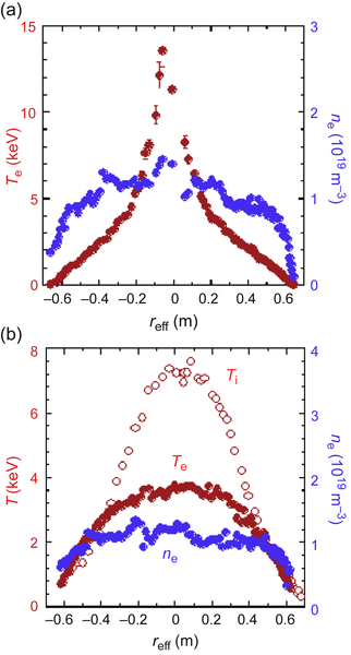
Figure 15.8 (a) Electron temperature profile with the improved energy transport region by high-power central heating of ECRH. (b) Ion temperature profile with energy transport barrier by high-power NBI heating with carbon pellets.
On the other hand, the internal transport barrier (ITB) found in ions is transient anomalous effect. A peaked ion temperature profile appears by injecting small carbon pellets with high-power NB. When the pellet is injected, the electron density increases abruptly and then decays. In this decay phase, the ion temperature (gradient) gradually increases accompanying ITB where the ion thermal diffusivity χi reduces (Fig. 15.8(b)). The increment of Zeff was about one just after the pellet injection, and then decreased to be ∼0.2 due to the formation of the “impurity hole” which will be described in the latter section. In the ITB region, it is also found that the toroidal rotation driven by the tangential NB is enhanced as the ion temperature (gradient) increases although input momentum by NB is unchanged. This fact shows that the momentum diffusivity also reduces. It is noted that the electron temperature does not change before and after the transition at the same density.
15.4.3. Confinement of high-energy ions
The confinement of high-energy ions is one of the issues of helical systems because the amount of trapped particles by helical and toroidal magnetic ripple is large. The amount of shift of particle orbit from the magnetic surface is affected by effective toroidal ripple, and depends on the position of magnetic axis Rax. The optimum position is Rax = 3.53 m where the confinement of high-energy particles is as good as tokamaks. Actually, the high-energy tail of perpendicularly accelerated ions is observed in the ICRH experiments. The tail is extended to 1 MeV, and the observed energy distribution of the tail can be explained well by classical collisions without any loss processes. Because the magnetic shear is large at plasma periphery and the magnetic field strength becomes large near the helical coils, the excursed ions outside the LCFS do not hit the wall and come back to the plasma confined region. That is, they are not lost directly [17] although they may suffer from charge exchange with neutrals at the periphery. Most of the trapped particles in helical ripple are confined due to the gradient B drift. The remaining trapped particles are lost from plasma but they are guided to the divertor, which is different from tokamak where the trapped particles by toroidal coil ripple are lost directly in the vertical direction.
The other loss process of high-energy ions is caused by the MHD activity. Because the energy of injected NB is very high (180 keV for hydrogen), they destabilize the Alfven eigenmodes [18]. The magnetic configuration of LHD is three-dimensional and has negative magnetic shear over a whole radial region in the low β regime. In this case, toroidal Alfven eigenmodes (TAE's) are excited. These modes are observed experimentally, but their effects on the high-energy particles are found only at the low toroidal magnetic field strength (<0.75 T) where the burst of TAE's enhances radial transport and loss of energetic ions.
15.4.4. Particle confinement
Particle transport also depends on the position of magnetic axis. Usually the radial profiles of electron and ion temperatures are peaked corresponding to the heating power profile. On the other hand, the density profile is flat or even hollow [19], which means that the inward convection is small. It is observed that the profile becomes slightly peaked when the plasma is shifted inward (smaller Rax). The particle transport is anomalous, and a typical value of the diffusion coefficient is 0.1–1 m2/s, and −2 to +1 m/s for the convection velocity.
A remarkable feature of helical systems is capability for high-density operation [20]. In the LHD, the central density of larger than 1 × 10²¹ m−3 is obtained with the internal diffusion barrier (IDB) [21]. This IDB mode is obtained by intensive multipellet injection, and a highly peaked radial density profile is realized as shown in Fig. 15.9. Different from the ITB which is observed at the good energy confinement region (inner shifted configuration), the IDB is observed in the outer shifted configuration (Rax > 3.7 m). The empirical scaling law on the upper density limit for helical systems, or Sudo Scaling, can be expressed as  [22]. The scaling shows a clear dependence on the input power and is different from the Greenwald limit of tokamaks [23]. The Sudo Scaling was derived from the experimental results from small and medium-size helical devices, and it also fits well with the gas-puff discharges of LHD where the density profile is almost flat. However, with pellet, the density profile becomes peaked and the line-averaged density exceeds the Sudo Scaling although the dependence on P holds. It was found that the Sudo Scaling holds at the plasma edge not in the whole plasma [24]. The limit may come from the thermal stability of the edge, that is, the power balance between the heat flow from the core and the radiation loss. The heat flow is proportional to the input power P, and the radiation power square of density n2, which leads to the power dependence of P0.5. In the IDB region (ρ < 0.5 in Fig. 15.9) the transport nature of particles is diffusive (no convection) and the diffusion coefficient is around 0.05 m2/s. It is noted that the thermal transport does not change even if the IDB is formed.

Figure 15.9 Typical radial profiles of electron density and electron temperature against the normalized radius. A clear transport barrier is shown in the density profile. In real coordinate a large.
When the central density becomes high, the pressure exceeds 150 kPa. Even the operating magnetic field strength is as high as 2.75 T, the central β(0) achieved 5% and the large Shafranov shift occurs, which breaks the equilibrium and limits the operation.
Impurity transport is complicated because the LHD has a thick ergodic layer outside the LCFS, which contains low-temperature plasma. Then the ergodic layer works as a screen for impurity ions. The dominant impurity is carbon because the LHD has carbon divertor plates. The first wall of LHD is made of stainless steel, but the metal impurity in the plasma is very small and has no effects on the plasma performance. The behavior of impurities in plasma is studied by using impurity pellets with several diagnostics from the visible to the soft X-ray range. In the normal discharges, the inward convection is found at the plasma core and the velocity is higher for higher Z impurity, which accumulates high Z impurity at the core [25].
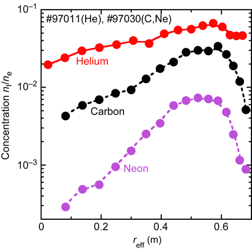
It is observed in tokamaks that the ITB accompanies a strong impurity accumulation [26]. On the contrary in the LHD, the extremely hollow impurity profile is found in the high ion temperature discharges [27]. Typical radial profiles of electron density, electron temperature and ion temperature are shown in Fig. 15.8(b). They have peaked or flat profiles, while the profiles of low Z impurities are hollow as shown in Fig. 15.10. The figure also shows that the hollowness is stronger for the higher charge number Z. Experimentally, a hollow profile grows as the ion temperature (gradient) increases, which cannot be explained by the neoclassical theory because the radial electric filed generated by the steep temperature gradient is negative and it makes inward convection theoretically. It is noted that the high ion temperature discharge utilized carbon pellet but the content of carbon at the center reduces only 0.3% of the electron density.
15.4.5. Stability and equilibrium
The MHD stability is secured by the strong magnetic shear in the LHD although the peripheral region is in a magnetic hill. A magnetic well is spontaneously formed by the Shafranov shift due to finite beta effect in the core region. Because there is no net large toroidal current, the pressure-driven modes such as interchange or ballooning mode are most hazardous in the LHD plasma. When the plasma approaches the stability boundary of ideal interchange modes, a strong MHD mode appears leading to a distortion of plasma pressure due to the flattening of Te profile around the resonant surface m/n = 1/1 for example. However no hard disruption such as in the tokamak occurs because the system does not have large magnetic energy associated with toroidal plasma current. There exists a bootstrap current in the LHD, but it is not so large as to affect the MHD stability. The toroidal current driven by the tangential NB is also small except in the case of very low-density operation. It is noted that the current drive efficiency by NB and its dependence on Te is almost the same as tokamaks. Since the LHD has co- and counter-injecting beamlines, the beam driven current can be used to control the profile of rotational transform for the MHD studies. It is even possible to diminish m/n = 2/1 resonant surface in plasma, and in this case the magnetic fluctuation disappears.
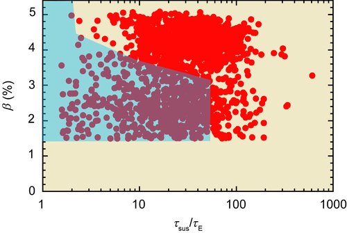
High-beta study has been carried out intensively at the low magnetic field strength thanks to the NB plasma initiation technique. The largest volume averaged beta <β> of 5.1% is obtained at Bax = 0.425 T. As can be seen from Fig. 15.3, the LHD has resonant surfaces m/n = 1/1, 2/1, 2/2, 2/3, 3/3, and so on in the plasma. The most hazardous mode is m/n = 2/1, and the amplitude of this mode frequency increases as the β increases. However it saturates and the β can increase. This saturation comes from the deformation (flattening) of local pressure gradient at the resonant surfaces through nonlinear process [13]. When a steep pressure gradient is made by pellet injection after the saturation, the strong MHD activities occur because it is already in the Mercier unstable region. The peripheral modes corresponding to such as m/n = 1/1 or 2/3 are always observed, but they are not crucial for the production of high-beta plasmas [28]. It should be noted that the high-beta discharge is very stable. The plasma can be sustained more than 100 times longer than the plasma energy confinement time (Fig. 15.11).
The fact that the plasma is still stable even in the Mercier unstable region although the low-n ideal mode may limit the stability is one of the major findings in the LHD. Thanks to this fact, the LHD can be operated in the optimum confinement region.
15.4.6. Plasma edge physics
The poloidal cross section of the magnetic geometry of LHD has a double-null structure due to a pair of helical coils (Fig. 15.2), and the null points rotate poloidally along the toroidal direction (ie, having a helical structure). At the start of the LHD project, these geometries were used as open helical divertor, that is, the water-cooling graphite target plates are located at the end of magnetic field lines (shown as “divertor leg” in Fig. 15.2). Therefore, these divertor plates form a helical line circulating around plasma. In order to control the neutral density at the edge region, recent efforts are focused on the modification of this open structure to a closed structure. The particle flow on this 3-D helical divertor has strong asymmetry. The 3-D numerical computation of particle flow indicates that up to 90% of particles flow into the torus-inboard side. Indeed, a concentration of recycling on the inboard side has been identified in the experiment. Therefore, to control the particle flux, it is sufficient to modify only the inboard side divertor to a closed one.
In order to realize a steady-state discharge under high-power heating, detachment of plasma from divertor plates is expected to reduce the heat load on them. To achieve detachment, it is essential to increase the neutral pressure around the divertor plates. It was found that the resonant magnetic perturbation (RMP) field has a stabilizing effect on the plasma radiating at its edge, and stable radiative divertor operation was achieved in LHD. The RMP is produced by the LID Coil shown in Fig. 15.1, which makes m/n = 1/1 resonant component. The LHD has a corresponding resonant layer in the edge stochastic region, where the remnant island is created. In the normal operation without the RMP, the radiation power gradually increases with  and when it reaches some level, a thermal instability starts to grow.
When that happens, the increase in the density is so rapid that it is difficult to stabilize the density rise, leading to discharge termination. With the RMP on the other hand, transition to an enhanced radiation state occurs, and the power load on the divertor plates reduces by a factor of 3–10. This enhanced radiation state can be sustained by the feedback control of gas puff. The plasma minor radius containing 99% of the total energy, however, reduces by about 10% due to the existence of a radiation layer. It is noted that this stable detachment occurs in the rather wide density range of 5–10 × 1019 m−3. The RMP makes a large m/n = 1/1 island at the plasma edge, and the radiation is enhanced there because of low temperature. The well-structured edge radiation is considered to provide a stabilization effect. The simulation shows that 65% of the input power is radiated by carbon and hydrogen in the entire edge region [29].
It is noted that the LHD has not suffered from severe ELM activities to date. Due to the existence of plasma in the thick ergodic region where the connection lengths are very large, the plasma pressure at the LCFS is finite and the gradient is small. Indeed, the MHD activity of m/n = 3/2 is observed in the experiments, and the corresponding resonant “surface” exists inside the ergodic region.
15.4.7. Long-pulse operation and plasma wall interaction
Demonstration of steady-state plasma operation is one of the important objectives of LHD. The target value is 1 h operation by 3 MW heating. Because the magnetic field exists in steady state, the performance of steady-state operation is required for the heating devices. The first trial was done by NBI [30]. The plasma was sustained 2 min by 0.3 MW beam injection. Since the negative ion source is not designed for steady-state operation, the temperature of the plasma grid increased monotonically and reached an upper limit even if the operation power was reduced. The most available heating power source for steady-state operation is the oscillator tubes for broadcast use, which are suitable for ICRF heating. The other components necessary for ICRF system such as antenna, waveguide, and tuner have been developed for the steady-state operation. The first successful result was the 54-min discharge in 2006, in which 0.4-MW ICRF and 0.1-MW ECRH were used. The parameters of sustained plasma were 0.4 × 10¹⁹ m−3 of electron density and 1 keV of electron temperature. The total input energy into plasma was 1.6 GJ, which was the world's record at that time [31]. The discharge was terminated by a sudden influx of iron. In the LHD, the first wall is made of stainless steel while the divertor plates are made of carbon. A strong interaction with the wall (sparking) might make a droplet of stainless steel enter the plasma.
After this experiment, the antennas were modified to improve the coupling between the antenna and plasma. The heating power also increased and the ICRF became able to sustain more dense plasma in short pulse discharges. Then the carbon influx turns to be the main cause of plasma termination for long-pulse operation rather than iron. A burst of carbon influx may change the plasma in front of antenna and impedance between them. It is observed experimentally that the divertor plates are covered with a stratified structure made by carbon, iron, chrome, and nickel [32]. Irradiation damage due to helium bombardment is seen in the subsurfaces of the deposited metal layers. This could be possible causes of exfoliation or dust, because helium plasma is used with hydrogen as a minority in the ICRF experiments. It is considered that one of the sources of impurity is the antenna itself, so new antennas were introduced to minimize impurity influx, which resulted in the success of 48-min plasma discharge by 0.9 MW ICRF and 0.3 MW ECRH. The plasma parameters were 1.2 × 10¹⁹ m−3 of density and 2 keV of electron temperature. The total input energy was 3.36 GJ, which is the new world record [33].
15.4.8. New trend of transport study (nonlinear, nondiffusive, nonlocal)
The LHD has various kinds of diagnostics that can measure the spatial profile of plasma quantities, because it is important to study the 3-D feature of LHD plasma. The LHD has large horizontal ports of 2.4 m in diameter, which enable us to access the full plasma cross-section with multichannel viewing cords aligned parallel to one another. More than 50 diagnostic instruments are installed including advanced diagnostics such as a 6-MeV heavy ion beam probe, a trace-encapsulated solid pellet, a scintillator probe, and others. As a result, the LHD becomes a good platform for investigating the properties of high-temperature magnetized plasma.
One of the active research fields is transport study of high-temperature plasma where the nonlinear, nondiffusive, and nonlocal characteristics are highlighted. The nondiffusive effect comes from the off-diagonal terms of transport matrix. In the experiments, the nondiffusive effect of momentum transport is observed as a “spontaneous rotation and intrinsic torque” [27], while the nondiffusive effect of particle transport is observed as a “particle pinch and particle exhaust” [19]. The sign and magnitude of these nondiffusive terms have been found to be sensitive to the turbulence state, which causes reversal phenomena. The nonlocal effect comes from the long-length (mesoscale) correlation between the micro-turbulences which govern the local transport. Although the transport is determined by the micro-turbulence, which has short correlation length, the turbulences at two separated locations (with the distance exceeding the correlation length of the turbulence) can have interference through the nonlinear coupling between micro-turbulence and meso/macro-turbulence or MHD activity. As an example, the edge cooling experiments with a tracer-encapsulated solid pellet show a significant rise in the core electron temperature gradually after pellet injection without any change of density [34]. Another example is the modulated ECRH experiment where the relation between heat flux and fluctuation intensity are not a simple monotonic function of the local electron temperature and its gradient. The results show a hysteresis of the heat flux and fluctuation amplitude to the change in temperature gradient during the modulated ECRH [35]. These facts show that the local perturbation can change the transport nature in macro scale. Although this dynamic response is transient, it may affect the robustness of transport in fusion plasma.
15.5. Engineering performance of LHD
15.5.1. Cryogenic system
The helical coil of LHD is the world's largest pool-cooled superconducting magnet. A conductor of the coils consists of NbTi/Cu strands, a pure aluminum stabilizer, and a copper sheath, the surface of which is oxidized for enhancement of critical heat flux in nucleate boiling [36]. Because of the additional heat generation by slow current diffusion into the thick, pure aluminum stabilizer, one-side propagation of a normal zone was observed several times at around 11 kA of the coil current, which is about 10% lower than the nominal operation current. The operation is limited under this value and the corresponding magnetic field strength of 2.75 T at Rax = 3.6 m. The one-side propagation is considered to be caused by electromagnetic interaction of the external magnetic field with the transfer current between the superconducting strands and the stabilizer. Under this limit, the helical coils have been operated stably for 17 years. In order to improve the cryogenic stability, an additional cooler was installed at the inlet of the coil so that the operating temperature is lowered to 3.2K from 4.4K. The critical current is increased by 5% [37], but it is reserved as a margin for the standard operation for plasma experiments.
The poloidal coils are made by cable-in-conduit (CIC) conductors with NbTi/Cu strands, which have high strength and rigidity against the electromagnetic force. The strand surface is uncoated to maintain good current distribution and heat transfer to the coolant. They were wound with a “double pancake” method. The poloidal coils have operated reliably.
During the experimental campaign, all the superconducting coils are activated once a day for 10 h, and have experienced this operating cycle more than 1600 times from the start of LHD. No deterioration is observed in coils after 17 years of operation. For all of the cryogenic system including a helium refrigerator, the rate of operation has been more than 98% except for the first year due to early failure, the thirteenth year for the failure of helium compressor, and the fifth year by the leak from a joint of a coolant pipe.
15.5.2. Negative ion–based NBI
The development of negative ion source was a crucial issue for the LHD project because high-energy NBI was needed as a main heating power source. Because there was no available negative hydrogen ion source in the world, the R&D started from the beginning of the LHD project. A large bucket source with a magnetic filter was adopted for the R&D. By using cesium, high current density of 250 A/m2 was confirmed, and the multigrid accelerator was developed successfully [38]. The specific feature of negative ions is its low ion temperature of around 0.1 eV, and hence the accelerated beam has very low divergence. The total beam divergence of 0.005 radian was achieved [10]. Beam convergence is important to reduce a geometrical interference with an injection port because the LHD is covered with a large cryostat and a tangential port has a long drift tube.
The advantages of using negative ion beam as the source of neutral beam is not only its high neutralization efficiency but also its low divergence and monotonic energy. The disadvantage is its low current density (an order of magnitude smaller than positive ions), that is, the ion source becomes huge. Also the control of cesium needs skill and is difficult especially for long-pulse operation. To date, the N-NBIs are working only in Japan (JT-60U [39] and LHD). In particular in the LHD, three N-NBIs are working as a main heating power source. The LHD plasma is usually generated every 3 min. This high repetition is possible because the magnetic field exists in steady state. Therefore, reliability and reproducibility are required for the heating system, but so far these are not as good as conventional positive ion–based NBIs.
15.6. Prospects for fusion power plant from the LHD
15.6.1. Design of heliotron fusion power plant: FFHR
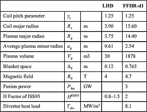
The heliotron fusion power plant has attractive features such as no need for current drive, no existence of current disruption, and suitability for steady-state operation. The wide space between helical coils is useful for maintenance of inner-vessel components. The 17 years of the experimental studies of LHD have demonstrated these features. The LHD also demonstrated additional favorable features of plasma such as high-density limit, stable high-beta operation, and impurity behavior. It was also found that the confinement of high-energy ions is as good as tokamak under the optimum magnetic configuration. Based on these results, design studies for the heliotron fusion power plant FFHR (force free heliotron reactor) have been carried out intensively since 1991. Several versions of FFHR have been examined, and the latest version is FFHR-d1 [40]. Fixing the fusion power of 3 GW, the maximum density of twice the Sudo limit, the alpha heating efficiency of 0.9 and the helium ash fraction of 0.03, a design window was analyzed on the machine parameters. The selected parameters for FFHR-d1 are shown in Table 15.2 together with those of LHD. A difference in design concept of FFHR-d1 from previous versions is that the temperature and density profiles are assumed to be determined by gyro-Bohm type transport similar as LHD.
As for the helical coils, there are 390 winding turns, and the required conductor current is 94 kA. A high current density of 25 A/mm2 is required in the winding area. For these coils, force-cooled CIC conductors are selected as the primary option. To reduce the degradation of critical currents due to strains (by cooling after heat treatment, winding, and cyclic excitations), Nb3Al is to be selected for strands in place of the presently used Nb3Sn for ITER, for example. Five-parallel winding is considered for the helical coils in order to limit the cooling length of supercritical helium shorter than 500 m so that the pressure loss is within the acceptable level under the condition of receiving a nuclear heating of 500 W/m3 at the innermost layer.
In the FFHR-d1, the divertors can be placed behind a blanket and radiation shield (as can be imagined from Fig. 15.12). Compared with the fast neutron flux at the blanket's first walls, magnitudes at divertors could be decreased by more than one order. In such condition, the copper might be used for the divertor plates. The maximum neutron wall loading is estimated to be 2.0 MW/m2. Compared with the average wall loading of 1.5 MW/m2 of the FFHR-d1 design parameter, the peaking factor is 1.3. A Flibe + Be/ferritic steel blanket system has been adopted as the primary candidate in the FFHR-d1 design for the high tritium breeding and neutron-shielding performances. After the optimization of blanket dimensions, the calculated net tritium breeding ratio of 1.18 is obtained with a 6Li enrichment ratio of 90%, and tritium self-sufficiency could be achieved.
Table 15.2
Design parameters of heliotron fusion power plant FFHR-d1
| LHD | FFHR-d1 | |||
| Coil pitch parameter | γc | 1.25 | 1.25 | |
| Coil major radius | Rc | m | 3.90 | 15.60 |
| Plasma major radius | Rp | m | 3.75 | 14.40 |
| Average plasma minor radius | ap | m | 0.61 | 2.54 |
| Plasma volume | Vp | m3 | 30 | 1878 |
| Blanket space | Δb | m | 0.12 | 0.765 |
| Magnetic field | B0 | T | 4 | 4.7 |
| Fusion power | Pfus | GW | 3 | |
| H Factor of ISS95 | HISS95 | 0.8–1.5 | 2 | |
| Divertor heat load | Γdiv | MW/m2 | 8.1 |

15.6.2. Engineering issues and R&Ds for the FFHR
Many of the engineering issues of FFHR are the same as those of a tokamak fusion power plant. The most important specific engineering issue of FFHR is to manufacture and construct huge helical coils. From this point of view, the high-Tc superconductor (HTS) option is an attractive candidate, considering the advantages of high cryogenic stability, high cooling efficiency, and facilitation of the winding process. High mechanical strength of the winding package is also expected due to the strong substrate used in YBCO tapes as well as by the stainless-steel jacket. The 100 kA-class HTS conductor design employs simple stacking of YBCO tapes. The YBCO tapes are embedded in a copper stabilizer and an outer stainless-steel jacket. The huge continuously wound helical coils can be fabricated by connecting half-helical-pitch conductor segments. A bridge-type lap joint is formed either by soldering or by mechanically connecting HTS tapes. The required electrical power for removing the Joule heating from all 7800 joints in two helical coils is evaluated to be <5 MW for the 20-K operation, which is acceptable. The R&D on fabrication of a conductor by connecting segments of 100 kA-class YBCO tapes has been carried out in NIFS successfully.
A self-cooled liquid breeding blanket is also an attractive option. In FFHR design studies, the molten-salt Flibe (LiF–BeF2) is the first candidate for a self-cooled liquid breeding blanket due to its superior safety (eg, low MHD pressure loss, low reactivity with air, low-pressure operation, and low hydrogen solubility). In particular, low hydrogen solubility is advantageous for keeping the tritium inventory low and for simplifying the tritium recovery system. However, due to the high equilibrium pressure of tritium in the liquid (a few kPa at 600°C for 3-GW fusion), the following two aspects have been major issues: reduction of tritium permeation through a heat exchanger, and use of low radioactivation vanadium alloys that have high mechanical strength up to and over 700°C but high hydrogen solubility (ie, hydrogen storage metal). In order to resolve those two issues simultaneously, mixing hydrogen-absorption metal powders (eg, Ti, Zr, and V) in molten salt to increase hydrogen solubility was being developed.
15.7. Summary
The LHD has been a flagship device of helical fusion research for these 17 years. The construction and the 17-year operation have proven that the LHD has attractive features for the fusion power plant. As for the plasma control, these features are the suitability for steady-state operation, no hard disruption, fairly good confinement of high-energy ions, high-density limit, stable high-beta operation, and favorable impurity behavior. The global energy confinement is found to be equivalent to tokamaks. Although some plasma performances (temperature and fusion triple products) are still behind those of tokamaks, the improved confinement regions (ITB and IDB) have been found both for energy and particle, and further optimization will be possible. To date, the LHD has not been allowed to use deuterium for plasma production, but that will become possible in 2017. Higher performance will then be expected if the mass dependence of the energy confinement is the same as tokamaks. It should be noted that the research on the 3-D physics in LHD can also contribute to the tokamak study. The LHD contributes a comprehensive study on the magnetic confined toroidal plasma.
Based on the results of LHD, design study of heliotron type fusion power plant is ongoing. A large device size is not always a disadvantage considering the reduction of heat load on the wall. An intrinsic helical divertor field configuration makes it possible to design a unique divertor concept for the power plant. The fabrication of huge helical coils would be realistic if the high-temperature superconductors were used.
The helical system has large flexibility in its design. The design concept of the “advanced stellarator,” Wendelstein 7-X is different from that of LHD. The Wendelstein 7-X begins operation in 2015, and new knowledge on helical plasmas will be obtained. By examining these results, further optimization of helical system will be possible. It is believed that helical system will be a firm base of an attractive fusion power plant (Fig. 15.13).

..................Content has been hidden....................
You can't read the all page of ebook, please click here login for view all page.