
9
Tore Supra—WEST
Abstract
Tore Supra, which began operating in 1988, was the first large tokamak to integrate all the technologies required to produce long pulse duration plasmas: superconducting magnet and cryogenic system, actively cooled plasma facing components and pressurized water loop, powerful heating and current drive systems, pump limiters and real-time protection and control capabilities. Significant achievements in all these technological areas have allowed for progressively improving the level of performance and addressing key operational issues. The 30 s initial objective has been greatly exceeded and in December 2003, the CEA-Euratom installation reached a record plasma pulse that lasted 6 minutes and 30 seconds, with 500 kA plasma current, holding the record for the energy injected/extracted from a pulse at 1.1 GJ. As a result of the technological success, important physics phenomena which govern steady-state plasma control have been investigated in depth such as current diffusion, thermal equilibrium of the plasma facing components, plasma-wall particle exchanges. Demonstration of fully non-inductive plasma scenario over very long duration and assessment of fuel retention in carbon wall are among the most noteworthy.
Today, to support ITER construction and operation, Tore Supra is undergoing a major change with its transformation into WEST (acronym for W (chemical symbol for tungsten) Environment in Steady-state Tokamak). To be in line with ITER, the circular poloidal cross-section of the plasma and the limiter configuration are turned into a D-shape poloidal cross-section of the plasma and a divertor configuration while the carbon is abandoned in favor of tungsten as plasma facing material. Armed with these elements, WEST is targeted at paving the way towards the ITER actively cooled tungsten divertor procurement and operation and mastering integrated plasma scenario over relevant plasma wall equilibrium time scale in a metallic environment.
Keywords
Divertor; Limiter; Long pulse operation; Plasma-facing components; Superconductivity; Tokamak; Tore Supra; WESTTore Supra, in which the first plasma was achieved in April 1988, has been operated with a circular poloidal cross-section, limiters, and ergodic divertor with carbon as plasma facing material until July 2011. After successfully pioneering the physics and technology of long pulse operations during 25 years, this medium-sized tokamak is presently being turned into a diverted device with tungsten as plasma facing material to support ITER1 construction and operation. This new configuration is called WEST, acronym for W (chemical symbol for tungsten) Environment in Steady-state Tokamak and the first plasmas in the WEST configuration are expected in 2016.
9.1. Background and objectives of Tore Supra
Supported by the EURATOM program, the French Tokamak Tore Supra, located at Cadarache in the south of France, was designed to investigate physics and technology issues related to long-pulse duration plasmas. At that time, the need to increase the pulse duration for the next step devices was clear, and none of the existing tokamaks were able to extend its flat top duration beyond a few seconds. While MHD and energy confinement characteristic time scales usually span well below 1 s, many other characteristic time scales like those of the plasma current diffusion, the wall inventory, the wall erosion largely exceeds these values. Besides, the technologies required to produce long pulse discharges were not readily available. Therefore, an accompanying program in parallel to JET, focusing on long pulse duration, was launched to complete the European fusion roadmap toward electricity production.
The ambition of Tore Supra was thus to integrate for the first time in a large2 tokamak all the technologies required to produce long pulse duration plasmas. In particular, it was intended:
• to build and integrate a superconducting magnet large enough to be relevant to a tokamak reactor;
• to integrate a large cryogenic system into the real environment of a tokamak;
• to control the plasma density and plasma–wall interaction by active methods, ie, pellet injectors, pump limiters, and ergodic divertors;
• to drive the plasma current by propagating waves, starting with lower hybrid waves.
Thirty seconds was originally identified as the appropriate target for addressing most technological challenges of high-power long pulse discharges, such as active cooling of the plasma facing components or the development of the continuous noninductive current drive and/or heating system.
This 30-s objective has been rapidly obtained, and a 1-min flattop discharge at 1 MA was achieved as early as 1992. A few years later in 1996, a record value of 250 MJ of injected energy was established in 2-min discharges, showing the limitation of the first generation of plasma facing components. A major enhancement, so-called CIEL,3 was then launched and a new set of plasma facing components were designed, manufactured, and installed to strongly improve the energy removal capability of the device. In 2003, the 1-GJ threshold of injected energy in a single tokamak discharge was exceeded in 6-min long, hot, dense, quasi-steady-state plasmas. Equilibrium control, current profile control, particle control and heat load control were demonstrated over very long duration highlighting the drawbacks of the carbon as plasma facing material, ie, tritium retention and erosion issues. Tore Supra still holds the world record of injected/extracted energy in a tokamak discharge.
9.2. Plant overview
The main rationales that guided the design of Tore Supra, which was led by Robert Aymar4 until its first plasmas, are briefly evoked hereafter.
First, to simplify the problem, it was decided that only the toroidal field coils are made superconducting. The poloidal field is yielded by water-cooled copper coils.5
The desire to build a high field superconducting magnet providing a meaningful experience for the next tokamak generation has led to choose the niobium titanium (Nb–Ti) as the superconducting material. It has to be noted that the tokamak variable fields, in particular during plasma current disruption, imposed specific constraints on the superconducting coils design. The consequence of the Nb–Ti choice is that superfluid helium at around 2K had to be used to cool it. Therefore the cryogenic system had to be consistently designed and sometimes specifically developed whenever the technology was not readily available.
A second choice was to thermally insulate the superconducting magnet by putting it into a vacuum chamber and to have two distinct volumes for the magnet and for the plasma. This led to the construction of two nested toroidal vessels, the intermediate volume of which being the evacuated magnet cryostat. To further reduce the heat losses, the 2-K superconductor is protected by cooled isothermal surface: a 4.5-K thick stainless steel casing which also serves as support for the winding and 80-K radiation shields on both sides of the magnet.
The machine is composed of six identical modules representing 1/6th of the full torus. The modules that are first assembled separately and then by 1/2 torus, contain the complete succession of the nested toroids: the inner vessel, the inner thermal shield, the magnet sector with three coils per sector, the outer thermal shield and the outer vessel. After assembly, each toroid must behave as a rigid and isothermal torus so that it can sustain the forces acting on it without the help of external structures. The advantage of this design is that only the weight has to be supported by elements at different temperatures. This minimizes the thermal losses and consequently the cryogenic system.
The poloidal field coils inducing the plasma current and maintaining the plasma loop in equilibrium are all connected in parallel. This eases both the construction of the device and the control of the plasma position but at the expense of difficult switching problems. For economic reasons the induction transformer had to be an iron core circuit.
The pulsed operation of the plasma current discharge dissipates heat in the toroidal magnet in a discontinuous way. To optimize the size of the cryogenic plant, extensive use of thermal buffers has been made in order to average the power spikes. For this purpose, large volumes of liquid helium have been provided in the coils themselves and in external ballasts [1].
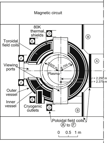
To facilitate the execution of the experimental program, it has been considered important to have large observation windows and that the operation of the machine must be reliable. There are 12 observation sections around the torus and the number of coils has been set at 18 so as to make the observation ports as large as possible.6 All cumbersome equipment, heat exchangers and ballasts, have been moved as far as possible from the diagnostic area. Concerning reliability, every new technical solution has been thoroughly tested before introducing it into the Tore Supra tokamak.
The main characteristics of Tore Supra are listed in Table 9.1 and a meridian cross-section is given in Fig. 9.1.
Besides the superconducting toroidal field coils, another specific feature of Tore Supra is the first wall design consisting of water-cooled elements. A pressurized water loop is used to exhaust the heat from these components. Over the exploitation period of Tore Supra, the cooling loop has been modified and updated [2]. It was operated at a pressure up to 4 MPa and a temperature in the range 100–230°C. The heat exhausted during plasma discharges is stored in a closed cooling circuit operating at a full flow rate of 1100 m3/h. Between discharges, the water is cooled at a reduced flow rate (140 m3/h) via heat exchangers and a cooling tower (11-MW capability). At least 9 MW could be removed during several hundreds of seconds of plasma operation.
Table 9.1
Main characteristics of the Tore Supra tokamak

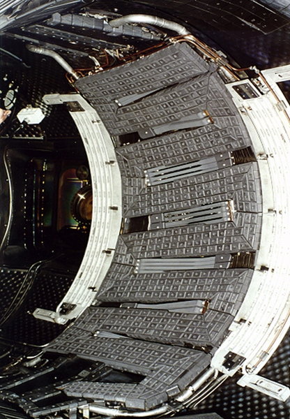
The initial actively cooled elements constituting the first wall were (see Fig. 9.2):
• a low field side first wall with 72 water-cooled stainless steel panels covering 60 m2;
• six bottom pump limiter modules of 0.4 m × 0.4 m each based on brazed graphite tiles;
• six ergodic divertor modules, consisting each of six current bars distributed along the poloidal co-ordinate, oriented in the direction of the magnetic field, protected by graphite tiles.
This first configuration [3], using the first wall as main limiter and a set of modular pump limiters has been replaced between 1999 and 2002 in the frame of the CIEL project by a carbon-fiber composite (CFC) armored toroidal pump limiter covering 7.5 m2 at the bottom of the machine [4]. This limiter led to the development of a new technology for the CFC/Cu bond and was, at its installation in 2002, the largest actively cooled high-heat-flux component in the world.
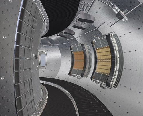
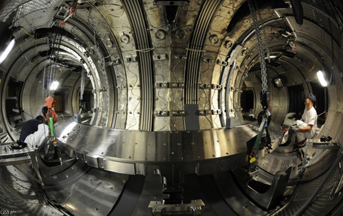
Fig. 9.3 shows a schematic cut view of Tore supra components from the plasma to the outer vacuum vessel with the materials, their respective operating temperature and pressure. Fig. 9.4 shows the same components during the assembly of the machine.
Since the mission of Tore Supra is to produce quasi steady-state plasma discharges, it has been equipped with different additional heating and noninductive current drive systems. Long pulse operation requires high input power to generate non-inductive current and heat the plasma up to the high temperature of interest [5]. Initially, the input power was shared between four systems but effectively focused on the lower hybrid and the ion cyclotron wave coupling. Indeed, the neutral beam injection system has been abandoned for plasma heating due to the large ripple losses and converted into a diagnostic beam while the electron cyclotron suffered from numerous technical difficulties in providing the required steady-state sources and only two gyrotrons with limited steady-state capability were finally installed on the machine [6].

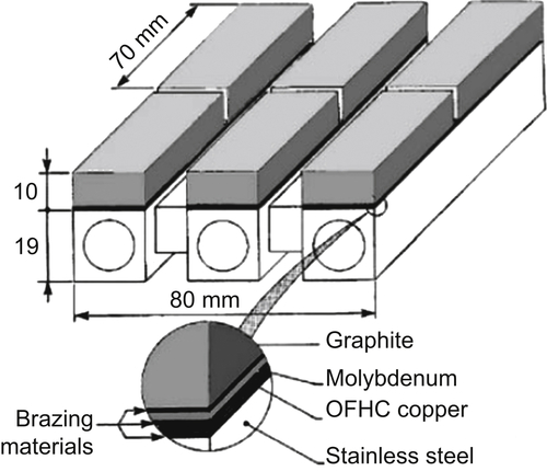
Figure 9.2 Inside Tore Supra inner vacuum vessel with the first generation of actively cooled plasma facing components: first-wall structure and bottom pump limiter modules based on brazed carbon tiles. Some set of windings constituting the ergodic divertor are also visible on the low field side of the first wall in the junction sectors.

The Tore Supra lower hybrid current drive system is composed of 16 × 500 kW klystrons at 3.7 GHz, whose power is coupled to the plasma through two launchers (“grills”) and provided the largest fraction of the noninductive plasma current [7]. The ion cyclotron heating and current drive system is composed of 3 × 4 MW tetrodes delivering the RF power (40–80 MHz) through three antennas located on the low field side of the machine [8]. The three RF systems have been extensively and successfully operated and the results in term of coupled power and injected energy during long pulse operations are summarized in Table 9.2.
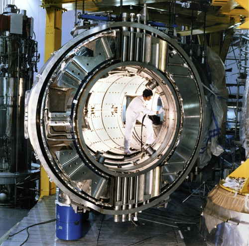
Figure 9.4 The torus during the assembly showing one toroidal field coil casing, the thermal shield, the inner and outer vessels and first wall elements.
The control of the plasma density and the plasma–wall interaction by active methods is another key requirement for long pulse operation. Tore Supra was equipped with three fueling methods [9]: gas puffing, pulsed supersonic molecular beam injection and pellet injection (see Table 9.3). Gas puffing was provided by a set of piezo-valves, toroidally and poloidally distributed around the vessel (up to 3 Pa m3/s per valve). Mainly used to inject deuterium, some of them were dedicated to helium and hydrogen to control the isotopic ratio, or to inject light impurities (nitrogen, neon, argon, etc.) to control the radiative power. Intermediate between gas puff and pellet injection, the supersonic molecular beam injectors are based on an original concept using a fast mechanical valve which can be located at a few centimeters from the plasma in the magnetic field and allows for the injection of very dense cloud of neutrals into the plasma. Two injectors were installed on the high field side and one on the low field side. Able to inject up to 2 Pa m3 within 1 ms at 10 Hz each, they showed a better fueling efficiency than standard gas puffing and an efficient density control with a feedback loop on the frequency.
Table 9.2
Tore Supra additional heating and current drive systems
| System | Frequency | Source power (MW) | Maximum power coupled to the plasma (MW) | Maximum energy injected in one discharge (MJ) |
| Ion cyclotron | 40–80 MHz | 12 | 10.5 | 265 |
| Lower hybrid | 3.7 GHz | 8 | 6.2 | 1070 |
| Electron cyclotron | 118 GHz | 1 | 0.8 | 25 |
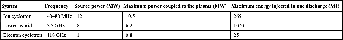
Table 9.3
Characteristics of the different fueling systems used on Tore Supra
| Continuous pellet injector | Centrifugal pellet injector | Two-stage light-gas gun pellet injector | Supersonic molecular beam injector | |
| Period of use | 1989–97 | 1991–99 | 2003–11 | 2002–11 |
| Number of pellets or pulses per discharge | 100 | 1 | Unlimited | Unlimited |
| Maximum frequency (Hz) | 5 | – | 10 | 10 |
| Pellet or beam speed (m/s) | 500–600 | Up to 4500 | 200–900 | 2000 |
| Atoms per pellet or per pulse (×1020) | 2–13 | 3.5–13 | 2–6 | 0.5–10 |
| Typical reliability (%) | 70 | 98 | 98 | 100 |

Looking for higher fueling efficiency, three pellet injectors were successively developed and operated. The first one aiming at fueling the plasma during long pulses was a centrifugal pellet injector designed and built by ORNL able to deliver about 100 pellets at a maximum frequency of 5 Hz with a velocity of 500–600 m/s. The second one was a two-stage light-gas gun pellet injector developed by CEA which allowed firing a single pellet per discharge at a velocity up to 4500 m/s and dedicated to pellet physics studies. Finally, to match the requirements of steady-state operations, a third pellet injector was built using the ice feed system developed by PELIN laboratory (Russia), able to provide H2 or D2 ice continuously. It is based on a screw extruder, cooled by liquid helium, producing a continuous rod of ice of rectangular cross-section. Pellets are cut in the rod and a fast electromagnetic valve releasing a small amount of propellant gas per pellet is used for pneumatic acceleration in the gun barrel. It has the capability to inject continuously pellets of adjustable size at frequency higher than 10 Hz, velocity between 100 and 900 m/s with a very high reliability. Pellets can be injected from four different poloidal locations on the same plasma: the first on the Low Field Side, the others on the High Field Side, regularly distributed from the top of the vacuum vessel to the equatorial plane. A fast selector and a set of guide tubes are used to convey the pellets to the High Field Side [10].
For particle exhaust, the bottom modular pump limiters and then the toroidal pump limiter associated with turbo-molecular pumping in the lower ports of the machine were mainly used to control the plasma density. Two configurations have been used: the “throat” limiter which collects ions drifting parallel to the magnetic field and the “vented” limiter which collects the Frank–Condon neutrals from high recycling areas [11]. Both methods provided efficient particle control at sufficient high density and the throat configuration was chosen for the toroidal pump limiter. Pumping rates up to 2.5 Pa m3/s of deuterium were obtained with 10 × 2200 L/s turbo-pumps.
Diagnostics system plays a prominent role in the scientific output of any experimental device. The diagnostic system of Tore Supra consists of roughly 30 diagnostics, covering a wide range of parameters from the core of the plasma to the plasma facing components coolant [12]. The long pulse capability introduce specific constraints on the diagnostics: their front parts have to withstand important thermal loads, usually requiring active cooling of critical parts while drifts in the measurements have to be avoided in order to provide reliable measurement and control during the whole discharge duration. Furthermore, the actively cooled components must be monitored in real time to avoid any damage that could result in deleterious water leak.
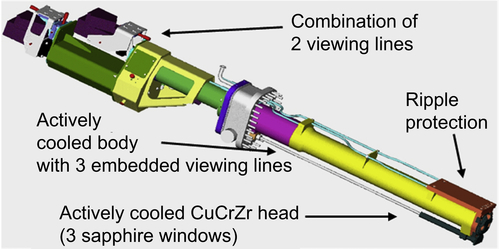
The IR thermography system dedicated to the monitoring of the plasma facing components was in place at the very beginning of the exploitation of Tore Supra. It has been significantly upgraded in the frame of the CIEL project with the installation of the improved in-vessel components [13]. The new IR thermography system has been designed to oversee the entire surface of the toroidal pump limiter and the five RF antennas. It is constituted of seven actively cooled endoscopes of 2.5 m long (see Fig. 9.5) distributed in the upper ports. Each endoscope is equipped with three viewing lines interfaced with two IR cameras. The first camera surveys 2 × 35 degrees of the toroidal pump limiter and the second one RF antenna. Digital cameras are used to protect the observed elements in real time against overheating. The spatial resolution of the overall system is approximately 4 × 4 mm2 for the antennas and 1 × 1 cm2 for the limiter with a sampling rate of 50 frames/s, allowing control of the surface temperature of the smallest PFC elements (20 mm) with an error <10%. The IR thermography system has played a crucial role in the success of Tore Supra long pulse operation [14].
Another important issue for long pulse operation is the monitoring of the in-vessel components degradation with thorough visual inspection without breaking the machine vacuum and conditioning. For this purpose, an Articulated Inspection Arm (AIA) has been developed, to demonstrate the feasibility of an in-vessel remote handling inspection carrier with limited payload (10 kg). The AIA robot is an 8-m long multilink carrier composed of five identical modules. It can be introduced in the vessel through a 20-mm-diameter port and is able to reach any in-vessel component. Fig. 9.6 shows the first deployment in Tore Supra, under ultra-high vacuum (1.4 × 10⁻⁵ Pa) and at a temperature of 120°C, performed in 2008 [15]. After deployment, plasma operation resumed without any particular wall conditioning.

9.3. Main achievements
9.3.1. Superconducting magnet
The first outstanding result of Tore Supra is the demonstration that superconducting magnets can be safely and reliably operated in the long-term in a large tokamak. Indeed, the system has been operated over nearly 25 years cumulating about 20 thermal cycle between 300 and 1.8K, 1300 plasma operation days and as much toroidal field ramp up and ramp down, a total magnetization time of approximately 13,500 h, and about 31,000 plasma discharges and 155 h of plasma with an availability >95%. The rhythm of the thermal cycle is given by the preventive maintenance and regulatory controls associated to the cryogenic plant.
The first two years of the operation of the magnet has been very eventful (see Table 9.4). After a few months of operation at reduced toroidal field (600 A) and the realization of the first plasmas, a short circuit occurred on one of the toroidal field coils. The coil had to be replaced by the spare coil, a major operation performed within six months. During the subsequent integrated acceptance tests, an abnormal overheating is observed on one coil at each Fast Safety Discharges (FSD), triggered to test the safety system at increasing current. Eventually, during the last FSD at 1450 A, a quench was induced in the coil but without any significant damage. The reason of this abnormal behavior was probably of the same origin as for the defect in the damaged coil, which meanwhile has been disassembled, inspected, repaired, and tested to be used as a spare coil. It was then decided to limit the nominal current of the magnet at the conservative value of 1250 A (4 T) for normal operation. In December 1989, a few days after the return of the plasmas, the safety system has been drastically tested when a quench occurred in another coil consecutively to a strong disruption. No other quench were recorded afterward.
Table 9.4
History of Tore Supra superconducting Toroidal Field (TF) system
| Period | Phase of operation |
| 1982–88 | Coils manufacture and magnet assembly All coils tested at 1400 A at CEA Saclay |
| 1988 | Acceptance test of the TF system at CEA Cadarache up to 600 A First plasmas Short circuit on coil BT17 |
| 1989 | Replacement of BT17 by spare coil BT19 Acceptance test of the TF system up to 1450 A (9.3 T on conductor) Quench of BT13 during an FSD from 1450 A Quench of BT4 during severe disruption |
| 1989–95 | Operation of the TF system at 1250 A Abnormal overheating in BT13 during FSD Repair and test at CEA Saclay of BT17 |
| 1995–2002 | Disappearance of abnormal overheating in BT13 during FSD after a thermal cycling between low temperature and room temperature Operation of the TF system at 1250 A |
| 2002–11 | Continuous data acquisition system in operation Long and energetic plasma discharges |
Since 2002, the data of the quench detection system, relying on five independent detectors for each coils associated with threshold levels and time delays (voltage, cold pressure, two temperatures, and ground current), are continuously recorded. The impact of different phases on the cryogenic load has been documented. It constitutes a useful source of information on the interaction between plasma physics and cryogenics for future fusion reactors. An illustration of the impact of different cryogenic loads on the temperature of one coil is shown in Fig. 9.7 for a full day of operation [19]. The heat load associated to plasma operation, particularly long pulse discharges, is very low as most of the energy is dissipated during the plasma initiation phase.
The main operational issue encountered during the operation of the TF system was found to be the spurious triggering of FSD by the quench detection. The FSD, which consists in commuting and dissipating the stored magnetic energy into an external dump resistor, is intended to be triggered only in case of a real quench of a coil. Indeed, during an FSD, the largest voltage is experienced by the coil (up to 500 V), which can produce short circuits on the bare conductors. In addition, two and a half hours are required by the cryogenic system to recover from the thermal loads (600 MJ of magnetic energy stored in the TF magnet). In 2003, an important effort has been done to harden the magnet protection system from electrical perturbations, usually induced by the RF heating systems during plasma operation, and the rate of FSD has been drastically reduced from typically five per year to less than one per year.

The successful operation of the TF magnet results from the following points:
• the importance of the integrated acceptance test phase, which preceded the operation that provided learning and training;
• the optimal monitoring of the refrigerator during plasma operation;
• the preventive maintenance;
• the constant improvement of the system to reduce as much as possible the spurious FSD.
Tore Supra, with its 18 Nb–Ti superconducting coils and its superfluid helium cooling bath at 1.8K, was a breakthrough in cryogenic refrigeration for large superconducting systems. Later installations of larger size, such as the CEBAF accelerator in the US or the LHC at CERN have built on the innovative technology of Tore Supra magnet system.
9.3.2. Development of actively cooled plasma facing components
The second requirement for high power long pulse operation is the steady-state heat exhaust and Tore Supra was the first tokamak to integrate an actively cooled first wall. From the very beginning, the Tore Supra team has been involved in the design, the fabrication, the qualification and the operation of actively cooled plasma facing components [20]. Table 9.5 gives the main characteristics of the most significant plasma-facing components which were developed and installed in Tore Supra vacuum vessel and their period of use.
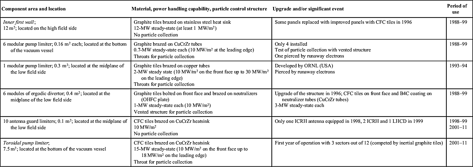
The initial inner first wall, which was used as the main limiter covered 360 degrees in toroidal direction and 75 degrees in the poloidal direction, for a total area of 12 m2 (see Fig. 9.2). It was intended to remove a maximum power of 12 MW in steady-state using a large wetted area. It was made of flat polycrystalline graphite tiles of 10 mm thickness brazed on stainless steel tubes with rectangular cross-section through a multilayer brazing joint (see Fig. 9.8). Of the 8600 brazed tiles, ∼2% exhibited flaws at the beginning of the plasma operation (localized overheated spots) and the quality of the brazed joints was identified as the main difficulty in the manufacturing. Indeed, the continuity of the brazed joint was very difficult to test as nondestructive evaluation methods were not available. At that time, transient infrared hot water tests started to be developed in order to identify metal/joint defects. Over the course of operation small cracks degenerated into larger ones and in some cases eventually became detached and fell down usually causing a plasma disruption. In 1994, ∼7% of the tiles exhibited a flaw [21]. Nevertheless, a few 1-min plasma discharges were performed.
Table 9.5
Main characteristics of the actively cooled plasma facing components operated in Tore Supra; main limiters are underlined
| Component area and location | Material, power handling capability, particle control structure | Upgrade and/or significant event | Period of use |
Inner first wall; 12 m2; located on the high field side | Graphite tiles brazed on stainless steel heat sink 12-MW steady-state (at least 1 MW/m2) No particle collection | Some panels replaced with improved panels with CFC tiles in 1996 | 1988–99 |
| 6 modular pump limiter; 0.16 m2 each; located at the bottom of the vacuum vessel | Graphite brazed on CuCrZr tubes 0.7-MW steady-state each (10 MW/m2 at the leading edge) Throats for particle collection | Only 4 installed Test of particle collection with vented structure One pierced by runaway electrons | 1988–99 |
| 1 modular pump limiter; 0.3 m2; located at the midplane of the low field side | Graphite tiles brazed on copper tubes 2-MW steady state (10 MW/m2 on the front face up to 30 MW/m2 on the leading edge) Throats for particle collection | Developed by ORNL (USA) Pierced by runaway electrons | 1993–94 |
| 6 modules of ergodic divertor; 0.4 m2; located at the midplane of the low field side | Graphite tiles bolted on front face and brazed on neutralizers (OHFC plate) 1-MW steady-state each (10 MW/m2) Vented structure for particle collection | Upgrade of the structure in 1996; CFC tiles on front face and B4C coating on neutralizer tubes (CuCrZr tubes) 3-MW steady-state each | 1988–99 |
| 10 antenna guard limiters; 0.1 m2; located at the midplane of the low field side | CFC tiles brazed on CuCrZr heatsink 10 MW/m2 No particle collection | Only one ICRH antenna equipped in 1998, 2 ICRH and 1 LHCD in 1999 | 1998–99 2001–11 |
Toroidal pump limiter; 7.5 m2; located at the bottom of the vacuum vessel | CFC tiles brazed on CuCrZr heatsink 15-MW steady-state (10 MW/m2 on the front face up to 18 MW/m2 on the leading edge) Throat for particle collection | First year of operation with 3 sectors out of 12 (competed by inertial graphite tiles) | 2001–11 |
The bottom pump limiters, which complemented the inner first wall providing active particle control, constituted the first attempt to operate high heat flux components in the range of 10 MW/m2 [22]. Composed of 25 CuCrZr circular tubes covered with 3-mm thick brazed graphite they were intended to extract 700 kW each. The quality of the brazed joint has been of primary importance, but sufficiently reliable bonding of all carbon tiles was never achieved. Well-bonded parts were able to extract 4 MW/m2 and peak values of 8 MW/m2 at the electron beam test facility at SNLA (USA). Following the poor results at the acceptance test (ultrasonic test), only four limiters were finally installed. A maximum of 0.6 MW was removed by a single module during 6 s (steady-state temperature reached after 2 s) and 1.2 MW were removed during 25 s by using three of them simultaneously. Like the inner first wall, these limiters exhibited flaws and cracks within the graphite tiles generating hot spots in the infrared images during plasma discharges and limiting their heat exhaust capability. Furthermore, one of these limiters has been damaged by a runaway electron beam through melting of the copper heatsink, leading to an in-vessel water leak. Indeed, the design of the limiter has not been properly optimized against runaway trajectories. Even if these components have not met all the expectations for long pulse operation many lessons were learned and the way was opened for the next generation.
In 1996, a 60 degree sector of the inner first wall was replaced by an improved sector with CFC tiles, offering better thermal and mechanical properties that would notably eliminate crack propagation under thermal stress. Many modifications were introduced in this new sector and no hot spot were observed anymore. With some enhancement of the remaining sectors, removal or recessing of the more defective tiles, this new sector allowed for the achievement of 2-min duration discharges. The limitation did not come from the inner first wall this time but from uncontrolled density increase, typically starting 1 min after the plasma initiation, originating from the outgassing of recessed components thermally loaded by the plasma radiation and insufficiently cooled. This issue was going to be addressed with the upgrade of the entire in-vessel components in the frame of the CIEL project.
Indeed, during that first decade of operation, the conception and realization of a complete new set of plasma-facing components was carried out with the idea to move to higher heat flux using copper alloy heat sink and CFC tiles. It took about five years from the design to the installation of these new components in Tore Supra through an effective collaboration between physicists and engineers, which brought considerable experience in the technology and industrial fabrication of plasma facing components.
The prime component in the new set is the bottom Toroidal Pumped Limiter designed to extract 15 MW of convected power in steady state. It is constituted of 576 radial high heat flux components, the so-called “fingers” (see Fig. 9.9 for details), relying notably on the Active Metal Casting bonding (AMC) technique developed by the Plansee Company through a CEA R&D contract. Extensive high heat flux thermal loading tests have been performed on prototypes. Average power density of 10 MW/m2 has been obtained for several thousands of cycles. The technology has been first successfully tested on the two limiters of one ICRH antenna where 200 “short” fingers have been exposed to the plasma in 1998. Despite these very promising results, the manufacturing proved to be very delicate. Problems appeared during series manufacturing of such a large number of complex elements that finally led to the development of a tile attachment repair process in order to allow for the achievement of the manufacturing. The complex nature of the CFC material and the high stresses induced by the electron beam welding of the CFC/Cu AMC tile are at the origin of most of the problems [23]. Nevertheless, thanks to a close collaboration between the supplier and the customer, the challenge has been met and the whole limiter was installed inside the Tore Supra inner vessel at the beginning of 2002 after about 4 years of manufacturing [24].

Figure 9.9 Schematic view of one high heat flux element of the toroidal pump limiter (0.5-m length, 2.5-cm depth and width); the 21 AMC (Active Metal Casting) tiles (6-mm thickness), the three plugs and Ni/SS pipes are electron beam-welded to the heat sink.
The toroidal pump limiter is completed by 108 stainless steel cooling panels that protect the entire vacuum vessel from radiation. They have been designed to extract up to 10 MW of radiated power, yielding a design heat flux of 0.3 MW/m2 (conservative peaking factor). In addition, six inner bumpers and one movable outboard bumper ensure the protection of the panels from plasma displacement and from runaway electron beams. They are based on large flat carbon composite tiles that are mechanically attached to an actively cooled cooper alloy (CuCrZr) heat sink structure by means of a spring system. Finally, actively cooled CuCrZr-based tubular protection structures have been installed in the upper part of the vessel to withstand the ripple losses. Due to the large toroidal magnetic ripple, fast particles may escape the core of the plasma focusing in between the coils and generating important localized heat fluxes. The final configuration of the plasma facing components is showed in the Fig. 9.10. Nearly 100% of the wall is now covered with actively cooled elements.
The benefit of the new configuration with enhanced heat exhaust capability was immediate and tangible. The long pulse operation readily became routine, and an impressive number of scientific results were promptly harvested [25]. It has to be noted that the pulse duration was no more limited by the plasma facing components heat exhaust capability but rather by the heating and current drive systems initially designed for 30-s plasma discharges and ultimately by the strong erosion of the armor material. Indeed, after 10 years of operation, the high heat flux elements of the Toroidal Pump limiter are still in a fair shape in terms of power exhaust [26] but the erosion of the front face of the Toroidal pump limiter exceeded 1 mm in the high heat flux areas, exposed to strong plasma–wall interaction [27].
The experience gained in the design, the manufacturing and the operation of actively cooled plasma facing component constitute crucial assets for ITER and the future devices.
9.3.3. Heating and current drive systems
A strong plasma heating and current drive is the third requirement enabling high power long pulse operations. Tore Supra played a major role in the development of two systems: the lower hybrid system which provides a powerful current drive, and the ion cyclotron system which offers a great flexibility of the heating and current drive scenarios.
The Lower Hybrid Current Drive (LHCD) system is based on so-called multijunctions launcher, successfully prototyped on the PETULA-B tokamak in Grenoble, and 3.7 GHz klystrons developed by Thomson Tubes Electroniques (THALES). These developments have also benefitted JET, which installed a similar LHCD system using the same klystrons and the same multijunctions launchers. On tore Supra 16 klystrons of 500-kW powered two antennas (or launchers or “grills,” see Fig. 9.11) through 20-m-long transmission lines. The first plasma discharges with LHCD were obtained in 1989 with one launcher, and from 1990 onwards with two launchers. The LHCD system has been operated since with a remarkable reliability resulting from strong development activity and upgrades continuously ongoing for both the launchers and the klystrons [28]. It has also demonstrated the capability to operate at high power density at the grill mouth (24 MW/m2), to generate plasma current over long duration discharge [29]. Indeed, the world record of injected energy in a plasma discharge has been obtained with 3 MW of LHCD power coupled to the plasma during more than 6 min.
The good diagnostic coverage for probing the plasma–wall interaction in front of the launcher and the possible adjustment of its radial position, has allowed studying and quantifying the heat load on the launcher from the interaction with fast particles and to measure the energy of the fast electron beam accelerated in the near field of the LH wave. Such knowledge is of great importance to develop RF antenna for long pulse operation. Indeed, the knowledge acquired by the Tore Supra team has resulted in the design of a “PAM” (Passive Active Multi-junctions) launcher for ITER [30].

The Ion Cyclotron Resonance Heating (ICRH) system is based on three antennas built according to the resonant double-loop concept, a design established in collaboration with the ORNL (USA). A first specific feature of these antennas (shared by the LHCD antennas) is their plug-in structure easing the maintenance and allowing for their radial displacement inside the vacuum chamber using a hydraulic jack with a stroke of 300 mm (see Fig. 9.12). A second specificity of the antennas is the active cooling of the front parts, required by long pulse operation. Although the antennas are not CW, they could inject up to 120 MJ per pulse. The major originality of the antennas resides in its electrical layout which allowed a compact design and high coupling performance, but at the cost of increasing complexity in comparison with more classical antennas. Each antenna has been able to couple up to 4.4 MW to the plasma, which is the maximum generator output power on matched load. This result corresponds to a world record of 15 MW/m2 IC power density at the antenna front face (at the Faraday screen or 10 MW/m2 at the port section surface). Besides, the three antennas have coupled up to 10.4 MW representing 80% of the total generator power on matched load.
Figure 9.12 ICRH antenna front face showing the Faraday screen, the two radiating straps behind, and the two guard limiters on the side.
ICRH offers versatile heating and current drive schemes. Most of them have been explored during Tore Supra operation and the most robust schemes were progressively selected to become routine scenarios [31]. However, ICRH still suffers from sensitivity to the edge plasma parameters, especially on transient when matching systems are too slow. In steady-state regimes, the maximum RF power available often results from a trade-off between RF voltage stand-off and excessive heat loads onto the antenna faces. Safe operation was guaranteed by real-time safety systems.
Some specific technological choices first made on Tore Supra are now retained for the design of ITER ICRH antennas, eg, plug-in antenna structure with individual strap boxes, actively cooled of front faces, automatically matching algorithms, and real-time safety systems instead of preset settings.
9.3.4. Key ITER operational issues
Tore Supra has been operated with a steady-state toroidal magnetic field and long pulse discharges as foreseen in future fusion reactors. It put particular constraints on the conditioning of the first wall. If the classical techniques, such as baking and glow discharge cleaning, can be used for restarting the machine after an opening, the conditioning techniques used in between pulses were either inefficient in presence of the magnetic field, like helium glow discharges used to desaturate carbon walls from hydrogen, or effective only for a few seconds of plasma. Therefore, new methods have to be considered. Alternative low current plasma (<50 kA) conditioning consisting in series of consecutive plasma breakdowns (typically during 2 s at 5 Hz) followed by pumping phases (typically during 8 s) has been routinely used to recover after plasma disruptions [32]. However, this technique does not extrapolate to a reactor and ion cyclotron wall conditioning (ICWC) and to a lesser extent electron cyclotron wall conditioning have also been explored taking benefit of the steady-state toroidal magnetic field [33]. High hydrogen removal rates have been measured in helium ICWC discharges, but those techniques suffered intrinsically from radial and poloidal inhomogeneity, which can be partially corrected with the help of small radial and/or vertical magnetic fields. ICWC fuel removal by isotope exchange has been studied in details in the carbon environment of Tore Supra.
The permanent toroidal magnetic field and the flexible electron cyclotron system (movable mirrors allow steering the beams of the two gyrotrons) have allowed studying plasma startup in ITER-relevant low voltage conditions. Reliable plasma initiations were obtained at very low electric field using ECRH assistance (down to 0.15 V/m corresponding to 50% of the ITER available voltage) giving confidence in the ITER chosen startup scheme [34].
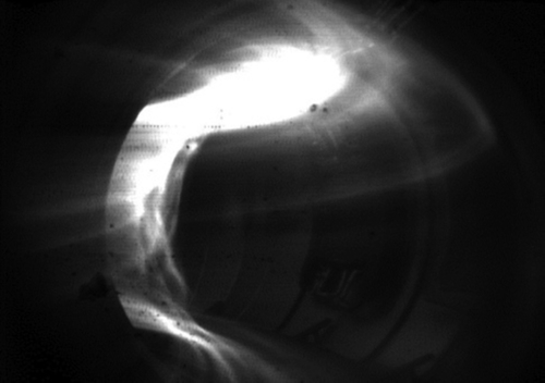
Tore supra also obtained important results in mitigating the effects of disruptions by way of massive gas injection [35]. Tore Supra is prone to generate runaway electron due to its high magnetic field and stable circular cross-section. Runaway electrons are indeed accelerated during most of major disruptions [36] and long runaway tails have been observed and studied as illustrated in Fig. 9.13. Runaway electrons have moreover been at the origin of several water leaks. Massive gas injection systems have thus been installed to confirm results obtained elsewhere and to quantify the effects of this mitigation technique on runaway acceleration (see Fig. 9.14).

Figure 9.13 Runaway electron beam impact on one Tore Supra inner guard limiter showing the tile material sputtering off the limiter (fast visible camera picture).
Reproducible runaway electron beam plateaus have been routinely produced which allowed for the first time the real time control of the position and current of the beam. A demonstration of runaway electron deceleration by massive gas injection has been reported [37]. Despite these promising results, mastering the runaway electron beam remains a major open issue for ITER.
9.3.5. Ergodic divertor experiments
The ergodic divertor (ED) concept implies the creation of a complete shell at the edge where the confinement is lowered. This is obtained by stochastization of the edge domain. For this purpose, a low amplitude but resonant perturbation δBr/Bθ ∼10−2 is generated. The radial magnetic perturbation is resonant on rational surfaces. The main objective is to increase the heat diffusivity across the stochastic layer. Two major beneficial effects are expected, namely a decrease of the plasma temperature in the volume controlled by the ergodic divertor and a spreading of the heat flux [38].
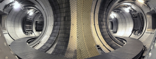
The ergodic divertor was implemented in Tore Supra to provide a divertor without severely decreasing the plasma volume in a torus with a circular cross-section. It consists of six modules, evenly-spaced toroidally, and located on the low field side of the vacuum vessel. Each module is composed of eight conductor bars made of cooled copper arranged in a poloidal direction forming a resonant helical winding along the flux lines. The space between the bars is occupied by actively cooled neutralizers with a vented structure in the target plate providing access to the pumping plenum connected by a duct to titanium pumps located on each side of the divertor coils. The front face of the coil and the neutralizers are covered with graphite tiles bolted or brazed on the water-cooled circuit [39] (see Fig. 9.15).
Part of the experimental time was dedicated to validating the change in the magnetic equilibrium properties by the ergodic divertor. A first result was the identification of a resonance effect. The resonant safety factor (qedge ∼3) and the width of the resonance which could extend over 20% of the minor radius at full current in the coils, both predicted and used in the design, were recovered. The overall confinement is maintained in spite of the loss of the edge volume. Interestingly enough, the access to high plasma currents is permitted as the last closed flux surface can be maintained at a safety factor of about 2. Unfortunately, no H mode barrier could be produced, due in particular to the difficulty of coupling ICRH in these edge conditions, but the compatibility with steady-state regimes and especially those implying internal transport barriers is in principle good. Moreover, technical achievements such as the implementation of internal coils and actively cooled neutralizer plates without failure were demonstrated with the achievement of pulse of 30 s duration with LHCD.
Experimental evidence for the three density regimes (linear, high recycling, and detachment) is reported. The low critical density values for transitions between these regimes indicate that similar parallel physics governs the axisymmetric and ED, despite the open configuration of the latter. Measurement and understanding of these density regimes provided a means for feedback control of plasma density and an improvement in ion cyclotron radiofrequency heating coupling scenarios. Experimental data also indicated that particle control with the vented target plates is effective. Finally, increase of both impurity control and radiation efficiency has been evidenced and well documented.
Meaningful advances in both the performance of ED and in the understanding of the ED physics have been achieved [40]. Although the level of investigation, and thus the confidence in the results, remains below that of the axisymmetric divertor, the ED can be considered as a possible divertor in future experiments to control the plasma–wall interactions.
9.3.6. Long pulse experiments
The fundamental mission of the Tore Supra tokamak is to open the route toward long pulse discharges in order to investigate key phenomena which govern steady-state plasma control: current diffusion, thermal equilibrium of the plasma-facing components, plasma–wall particle exchange, etc.
The development of long pulse discharges is intimately linked to the development of robust control schemes in particular to avoid overheating and handle unexpected events like UFO. It sometimes coincides with the search for the limitations of the machine. Once a stable plasma scenario is established, which usually requires long developments, one will inevitably challenge the technological boundaries and may reveal any weak link in the machine. In 1992, a noteworthy 1-min flat-top 1-MA discharge was performed with 2.5 MW of LHCD and the main limitation came from the available poloidal flux. In 1996, at 0.8 MA, duration could be extended to 120 s, limited this time by in-vessel uncontrolled outgassing of poorly cooled components away from the last closed flux surface slowly heated by the plasma radiation. In 2000, the upgrade of the first wall with components with improved heat exhaust capability solved this issue. Therefore in 2003, the world-record breaking, 6-min, 0.5-MA discharge was achieved accounting for 1 GJ of injected and extracted energy [41]. As shown in Fig. 9.16, all the plasma parameters were remarkably kept constant during the whole discharge, the plasma current being fully noninductively driven by 3 MW of LHCD. The pulse limitation came at that time from the LHCD system itself, which was still equipped with the initial klystrons originally designed for 30 s operation.
In 2006, dedicated experiments aiming at performing discharges with the maximum available RF power (combining LHCD and ICRH, limited to 30-s pulse by the ICRH system) encountered a new operational limitation [42]. Indeed, above 8 MW of RF power a slight increase of the injected power (typically by 200 kW) often resulted in a disruption. Nevertheless, a few 10 MW-30 s 0.9 MA discharges could be performed, which is representative of ITER in terms of average power density and heat exhaust. After thorough analysis, the cause of these disruptions has been attributed to the flaking of accumulated carbon deposits on components in the vicinity of the last closed flux surface. The power threshold for disruption occurrence was found to decrease pulse by pulse. At the end of the 2007 campaign, which consisted in performing repetitively more than 160 2-min identical pulses for wall retention studies [43], the power threshold eventually went below 2 MW. The careful scraping of the surface of all the limiters during the following shutdown allowed to restore the operational domain and 12 MW of RF power (maximum power level achieved in Tore Supra) has been readily coupled to the plasma without any disruptions and UFO. Thick carbon deposits up to a few 100 of micrometers and including metallic impurities have been removed from the private flux area at the surface of the main limiter. The time constant for the carbon deposit to grow to the critical thickness is estimated to be the time necessary to inject approximatively 100 MJ of additional power (∼2 years of operation of Tore Supra). This erosion issue is tightly connected to both the use of carbon as armor material and the use of limiter (see Fig. 9.17). Whether it will be an issue for ITER with beryllium deposit is difficult to state as the divertor configuration should be less sensitive to the flake perturbation due to the higher distance between the flake and the confined plasma.

Figure 9.16 Six-minute LHCD discharge with record injected energy of 1.07 GJ in the LHEP regime (#32299, Ip = 0.5 MA, BT = 3.4 T). (a) Transformer flux, central line density, and LHCD power; (b) diamagnetic energy compared with the ITER-scaling prediction for thermal L-mode; (c) central electron/ion temperatures; (d) neutron rate and effective charge; and (e) q profiles from 20 to 250 s, obtained from the code CRONOS.
During the last campaign in 2011, new fully steady-state klystrons were available and the LHCD power could be increased up to 5.3 MW during a 1-GJ discharge of 160 s combining 1 MW of ICRH [44]. The operational domain for long pulse operation has been extended toward higher densities and non-inductive current. New limitations have been faced related to MHD stability of the achievable plasma current profiles or overheating due to fast particle losses.
Designing plasma scenario for long pulse operation is very demanding. The realization of discharges with dominant noninductive current has allowed in-depth investigation on a number of physics phenomena governing the plasma behavior whenever the ohmic field is vanishing [45]. Significant advances have been made in the fast electron physics [46]: the discovery of a new improved confinement regime, the so-called LHEP regime, which exhibit an electron internal transport barrier in the narrow central region where the magnetic shear vanishes (r/a < 0.3, related to the location of the LH power deposition, see Fig. 9.16); the discovery of a new tokamak plasma regime with nonlinear temperature oscillations (the so-called O-regime); specific MHD regimes associated with reversed safety factor profiles; investigation of the anomalous particle transport, obtained in fully noninductive zero loop discharges; and the first experimental demonstration of synergy effects between cyclotron and lower hybrid current drive in steady-state plasma.
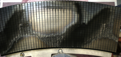
Figure 9.17 Picture of a toroidal pump limiter sector (20 degrees) after an exposure to the long pulse plasma campaign of 2007 (160 × 2-min pulses and 5 h of plasma) showing the net erosion (white areas), the thin deposit (dark/gray areas) and the thick deposit (rough areas) zones. The erosion/deposition pattern is due to the toroidal magnetic field ripple.
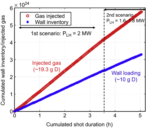
Besides the scenario development for long duration plasma, Tore Supra offered unique conditions to study fuel retention in plasma-facing components which is a major concern for the fusion reactor for safety issue. Its unique actively cooled first wall which guaranteed a constant temperature of the plasma-facing components over the discharge combined to plasma exposure of several minutes allowed bringing outstanding results on the retention in carbon plasma-facing components [47]. Constant retentions rate were measured notably depending on the LHCD power, with no sign of saturation (see Fig. 9.18), mainly linked to the erosion of the carbon that forms deposits with high deuterium concentration (see Fig. 9.17 for the structure of the deposits). These results contributed to the decision taken recently to remove carbon from ITER divertor.
The interest and success of the Tore Supra program in the physics of noninductive discharges and in the physics of plasma–wall interaction over long duration has influenced, and will continue to influence, the developing of various superconducting tokamak projects worldwide that will exploit and extend the Tore Supra legacy in the next decades.
9.4. Preparing ITER operation: the WEST project
Tore Supra has been leading the way toward mastering power exhaust over long pulse operation over the past 25 years, developing an exceptional expertise to solve the associated technological, operational and physics issues. With the WEST project (Tungsten (W) Environment in Steady-State Tokamak), this expertise is turned in support of the ITER divertor. The divertor is a crucial component, handling the highest heat and particle loads in the vessel, and allowing access to high plasma confinement regimes (H mode). ITER plans to operate with an actively cooled tungsten divertor, bringing specific challenges.
• From the technology point of view, although prototypes have been successfully built and tested for ITER, large scale industrial manufacturing of actively cooled tungsten components has never been performed and remains a challenging step.
• From the operation point of view, these components have been tested in dedicated high heat flux facilities or plasma–wall interaction linear devices, but have never been run in a tokamak environment under combined heat and particle loads.
• From the physics point of view, using tungsten plasma facing components restrains the operational window, as the tolerable tungsten concentration in the plasma (≪10−4) is much lower than for carbon (few %). Acceptable tungsten control has been obtained in JET and ASDEX Upgrade. However, the control of tungsten contamination over long discharges has not yet been addressed so far.
The WEST project is targeted at solving these issues, minimizing risks for the ITER divertor procurement in terms of cost, delays, performance, and gaining time for its operation. It consists of implementing a divertor configuration and installing an ITER like actively cooled tungsten divertor in the Tore Supra tokamak, taking full benefit of its unique long pulse capability [48].
The project has been initiated based on a joint analysis of tungsten divertor R&D needs with the ITER Organization. In addition, a strong connection is being developed with the Domestic Agencies in charge of procuring the ITER divertor targets (F4E for Europe and JAEA for Japan), as well as with the ITER partners. In particular, the program of WEST is developing strong links with new superconducting long pulse fusion devices (such as EAST, JT-60SA, KSTAR, SST-1, or the W7X stellarator), as well as with tokamaks running with metallic walls (ASDEX Upgrade and JET) and plasma–wall interaction devices (Judith, Gladis, Magnum PSI, PISCES). At the national level, WEST is supported by the French Federation of Research on Magnetic Confinement Fusion (FR-FCM), gathering the efforts of French research institutions in the field of fusion.
The WEST project radically changes the Tore Supra tokamak in two ways: transition from a limited to a diverted configuration allowing access to H-mode regimes and transition from a carbon to a tungsten environment more relevant for next step devices. Therefore, to avoid any confusion and to increase the visibility of the WEST program it has been decided to rename the tokamak, WEST, the Tore Supra name referring to the carbon limiter former era.
WEST complements the ongoing effort on tungsten R&D worldwide, as it provides an integrated test environment, bringing together the high heat flux technology of the divertor and the long pulse tokamak operation.
9.4.1. From limiter to divertor configuration
The transformation from the circular limiter geometry of Tore Supra to the required X-point configuration is achieved by installing a set of water-cooled copper coils inside the lower and upper parts of the vacuum vessel. A wide range of plasma equilibria is accessible, from lower single null (see Fig. 9.19) to upper single null passing through double null geometries. The divertor coils symmetry allows an adequate matching between plasma and RF heating and current drive antennas shapes. Plasma volume is reduced by about 40% (from 25 to 15 m3). The divertor coils design allows steady-state operation at plasma current up to 0.8 MA.
Stabilizing plates are integrated in the upper and lower part of the divertor structure to improve the vertical control of elongated plasmas. An outer baffle complements the divertor structure to enhance the particle exhaust. The incident heat flux on the divertor target can be controlled by adjusting the plasma heating power level and/or the magnetic flux expansion at the target. Heat fluxes in the range expected for ITER will become routinely accessible (10–20 MW/m2).
The high aspect ratio of the plasma resulting from the reduction of the plasma minor radius, A = 5–6 (R/a = 2.5 m/0.4–0.5 m), is complementary to those of existing tokamaks and should therefore allow an interesting expansion of the international tokamak physics databases.
9.4.2. From carbon to tungsten PFC
The lower divertor target design is closely based on the design of ITER tungsten divertor, using actively cooled tungsten monoblock concept, ie, tube-in-tile concept. The same tungsten tile geometry and bonding to the heatsink are used to build the plasma facing unit (PFU) [49]. As illustrated in Fig. 9.20, the WEST PFU is representative of the straight part of ITER PFU, which corresponds to the strike point region.

Figure 9.19 Cross-section of WEST showing the vacuum vessel, the in-vessel coils, the stabilizing plates, the pumping baffle, and the plasma facing components arrangement.

Figure 9.20 Comparison of a WEST plasma facing unit (PFU) with an ITER PFU and schematic view of the W-monoblock technology.
The upper divertor target and the remaining actively cooled plasma facing components rely on tungsten coating technologies on CuCrZr heatsinks. An overview of the plasma facing components layout is given in Fig. 9.21.
With 456 PFU, and 15,960 monoblocks, the WEST divertor lower target represents half a vertical target of ITER divertor in terms of number of PFU and 14% in terms of monoblocks. Such a quantity offers the capacity to qualify manufacturing process at the required industrial scale through a first significant series production. The WEST divertor is made of 12 modular 30 degrees toroidal sectors, which can be individually and easily removed, offering a flexible configuration for testing different concepts, running dedicated experiments (involving, for example, deliberately damaged elements) and allowing for frequent postmortem analysis of components.
9.4.3. Testing ITER divertor PFC in relevant tokamak conditions
Assessing the performance of the ITER like tungsten divertor under combined plasma loads in a tokamak environment (steady state and transient heat loads, combined particle/heat loads, etc.) is a high priority of the WEST program to ensure efficient ITER operation [50].
Power handling studies will be focused on testing the ITER like tungsten divertor under relevant steady-state heat fluxes (10–20 MW/m2) as well as under a large number of sub threshold transients (>105 ELMs). The modular design of the WEST divertor sectors provides a means to accommodate “à la carte” experiments such as testing different material grades, investigating monoblock geometry and shaping, aging of predamaged or misaligned components, melting experiments, etc. It will also allow one comparing components supplied by different manufacturers.
As far as PFC aging is concerned, experiments with high integrated particle flux to the vessel walls, comparable to that of a nominal ITER discharge, typically ∼1027 D/m2 at the strike point for the nominal 400 s, Q = 10 discharge, are foreseen. Reaching these values of the integrated particle flux requires years of operation in short pulse fusion devices, but is achievable within days/weeks with WEST. The synergistic effects of combined exposure of the components to steady-state heat loads/transient heat loads/high integrated particle flux is a high priority issue for ITER, as it might impact PFC lifetime and plasma performance.
Regarding operation, conditioning of the all metal WEST facility is also part of the program together with specific control issues regarding safe PFC operation, such as developing the wall protection system including both the control tools and associated diagnostics. These aspects are highly relevant for ITER.
9.4.4. Long pulse H-mode operation in tungsten environment
The WEST configuration will provide the capability to run long pulses in the high confinement regime (H mode) foreseen for ITER. Combining the existing powerful LHCD system, the existing ICRH sources completed by three new ELM-resilient ICRH antennas with CW capability, a large operational domain is accessible ranging from 30 s inductive discharges at the maximum heating power of 15 MW to fully steady-state operation over 1000 s at up to 10 MW of additional power [51].
The specific features of WEST offer unique opportunities to untangle some important parameters such as large aspect ratio, dominant electron heating, compact divertor geometry, no momentum source, etc. The issue of controlling the tungsten contamination of the plasma over very long pulses will be a crucial part of the program to be addressed, complementing the ongoing effort in the other shorter pulse metallic devices.
9.5. Conclusions and perspectives
Tore Supra has been pioneering long pulse operation in tokamaks during 25 years. It has demonstrated that superconducting magnets can be operated reliably on the long term in a tokamak. It has addressed the challenge of power exhaust in carbon environment by integrating and operating for the first time actively cooled high heat flux element in a tokamak. Major progresses in steady-state high-power high-frequency heating and current drive systems have allowed increasing the pulse duration beyond several minutes. Outstanding research on continuous plasmas has been carried out that contributed notably to the decision to eliminate the carbon from ITER divertor. All the experience and know-how gained on the technology of steady-state operation and the mastering of long pulse plasma discharges has laid solid foundations for the construction and the future scientific exploitation of ITER, the next-step long pulse tokamak.
While ITER construction has begun, Tore Supra starts a new life with its transformation into a steady-state diverted tokamak with tungsten plasma-facing components named WEST (Fig. 9.22). WEST intend to pave the way toward the ITER actively cooled tungsten divertor procurement and operation and master integrated plasma scenario over relevant plasma–wall equilibrium time-scale in a metallic environment.
The WEST planning is thus aligned with the ITER divertor procurement and operation planning. WEST operation, which is scheduled to start in 2016 [52], will be phased to make the best use of the ITER-like divertor elements as they become available. In the first phase, it is planned to operate with a mix of actively cooled ITER-like divertor elements and inertial tungsten-coated divertor startup elements. Full power will be available, but plasma operation will be limited in duration by the inertial divertor elements. In the second phase, the full actively cooled ITER-like tungsten divertor will be available, allowing long pulse operation. The contributions of WEST are expected in three steps:
• WEST divertor production: optimization of the industrial-scale production,
• WEST operation phase 1: demonstration of power-handling capabilities of the ITER-like divertor in tokamak environment,
• WEST operation phase 2: demonstration of integrated long-pulse H mode; exposure of the ITER-like divertor to high fluence plasmas; investigation of advanced regimes.
The WEST platform will be run as a user facility, open to the EUROfusion Consortium and all ITER partners. Major fusion partners have already demonstrated their interest for WEST and participate to the construction phase.
WEST project will contribute to the exciting challenges of mastering power exhaust over long pulse in preparation of ITER, and to solving the associated technological, operational, and physics issues. WEST provides to the fusion community an opportunity to anticipate current unknowns on the way to long pulse operation in a metallic environment before they are encountered in ITER, and identify and validate solutions.
..................Content has been hidden....................
You can't read the all page of ebook, please click here login for view all page.