
11
National Spherical Torus eXperiment
Abstract
The National Spherical Torus eXperiment (NSTX) is a medium-sized, low-aspect ratio, spherical tokamak (ST) whose aims are to study 1) the unique physics properties of the ST, 2) complement higher aspect ratio tokamak physics and support ITER, and 3) establish attractive ST operating regimes for future ST-based fusion energy producing devices. Research on NSTX over the past 15 years has been broadly based. Transport and turbulence studies focused on identifying the source of the highly anomalous and dominant electron energy transport, as well as electromagnetic effects on turbulence, in neutral beam and radio frequency heated L- and H-mode plasmas. Macrostability research has identified the importance of kinetic effects in determining high-bT stability, and a multi-parameter-based algorithm was developed capable of predicting plasma disruptions with a near 95% success rate. Energetic particle driven Alfvén Eigenmodes were found to have a significant effect on the fast ion population and resulting beam-driven non-inductive current drive profiles. High heat fluxes were mitigated successfully by operating in a “snowflake” divertor configuration, and test stand studies revealed the surface chemistry necessary to understand lithium wall conditioning, a technique used routinely during the last half of NSTX’s operational lifetime. Finally, solenoid-free operation studies explored non-inductive generation and maintenance of the plasma current; non-inductive operation is a critical component of future ST devices. NSTX has just undergone a major upgrade, which allows for an expanded operating and physics parameter range. The Upgrade also includes the addition of a second, more tangentially directed, neutral beam injector for added power and pressure and current profile control. NSTX-Upgrade operation commenced in 2015.
Keywords
NSTX; NSTX-U; Spherical Torus; Spherical Tokamak11.1. Introduction
The National Spherical Torus eXperiment (NSTX) is a medium-sized spherical tokamak (ST) whose aim is to:
1. understand the unique physics properties of the ST
2. complement tokamak physics and support ITER
3. establish attractive ST operating scenarios and configurations
The unique ST properties consist of large toroidicity, very high βT, high vfast/vAlfvén, and high E × B shearing rate. To achieve the second mission element, NSTX exploits its unique ST features to improve tokamak understanding, such as by leveraging the ST parameter range to benchmark and validate theories that could then be used to predict performance in future devices. Furthermore, NSTX would contribute to ITER final design activities and research preparation. The goal of the third mission element is to utilize advantages of the ST configuration for addressing key gaps between ITER performance and the expected performance of an ST-based fusion nuclear science facility (FNSF) [1] or ST-based DEMO [2]. One important gap is fully noninductive operation.
In order to accomplish its mission, NSTX was designed, constructed, and operated at the Princeton Plasma Physics Laboratory, Princeton University, Princeton NJ, USA, with the following capabilities [3,4]:
1. R/a = 0.85/0.68 m ∼ 1.26
2. Inductive plasma current initiation using an ohmic solenoid, aided by electron cyclotron heating
4. Ip up to 1.5 MA, BT up to 0.55 T
5. D+ or He++ plasma operation
6. Plasma elongations κ up to 2.5 and triangularities δ up to 0.8
7. Ability to operate in double-null (DN), lower-single-null (LSN), or upper-single-null (USN) divertor configurations. More recent configurational development included operation with a “snowflake” divertor [7].
8. Auxiliary heating powers up to 7.2 MW of D0 neutral beam injection, and up to 6 MW of high harmonic fast wave (HHFW) heating and current drive. The auxiliary heating and maximum current capabilities allow for plasma operation at low collisionality.
9. A close-fitting conducting shell for passive stabilization of external MHD modes such as kinks and resistive wall modes (RWMs), and active control of error fields and MHD modes through application of n = 1 to 3 edge magnetic perturbations (MP) by a set of ex-vessel midplane coils. These capabilities allow for longer-pulse lengths (up to 1.6 s) and achievement of higher βT, βN by stabilizing MHD modes and delaying disruptions.
10. Different wall conditioning options, including:
a. boronization and between-shots helium glow discharge cleaning (HeGDC + boronization)
b. predischarge injection of lithium wall coatings by two downward-pointing LIThium EvaporatoRs (LITERs) [8]
Lithium as a plasma-facing component (PFC) was also investigated with four heated liquid lithium divertor (LLD) modules [9].
A full schematic of the NSTX vessel and an interior view is shown in Fig. 11.1(a) and (b). The vessel has electrical insulation between the center stack and outer vacuum vessel (the “CHI gap”) to allow for a 2 kV DC bias voltage for CHI. Poloidal field (PF) coils are used for plasma shaping. The close-fitting shell is made out of copper, with graphite tiles for plasma facing components. The close-fitting shell, as well as lithium wall conditioning, HHFW and CHI capabilities are among the features that distinguish NSTX from the complementary MAST device, which will be described in the next chapter.
NSTX has a comprehensive set of diagnostics to measure plasma performance, including, but not limited to, electron temperature and density profiles from Thomson scattering, ion temperature, rotation and impurity density profiles from charge-exchange recombination spectroscopy (CHERS), magnetic field pitch (Bp/BT, where the subscripts ‘p’ and ‘T’ indicate poloidal and toroidal direction, respectively) from Motional Stark Effect (MSE) spectroscopy, midplane bolometer arrays, various spectroscopic diagnostics both in the divertor and main chamber for impurity content, magnetics (flux loops, Mirnov coils) with excellent spatial coverage and with the ability to measure magnetic fluctuations from DC up to the ion cyclotron frequency (∼MHz), high-k scattering and beam emission spectroscopy (BES) for measuring electron-scale and ion-scale turbulence, respectively, multienergy soft X-ray arrays for electron temperature and MHD mode measurements, gas puff imaging (GPI) for measuring edge turbulence, edge reflectometers, Langmuir probes in the divertor, visible and IR cameras (the latter for measuring heat loads on the PFCs), and Dα arrays.

NSTX began physics operation in February 1999 and operated for over a decade, until ceasing operation in October 2010 to allow for an upgrade of both the device and auxiliary heating capabilities. During the first year of operation, NSTX achieved plasma currents of up to 1 MA with optimized ohmic flux consumption, found ohmic confinement times increasing with density up to values of τE/τ89p ∼ 1 at ne/nGW ∼ 0.7  and then saturating at higher density, observed predominant n = 1 activity that led to sawteeth, reconnection events, or disruptions, and tested CHI, HHFW, and NB capabilities [4]. Even with low injected neutral beam power (∼2.8 MW), βT values of up to 18% were obtained.
With the introduction of higher levels of auxiliary heating power as well as enhanced operational capabilities over the next two years, NSTX made rapid progress toward achieving its goal of high βT, long-pulse performance [10]. Results included:
• βT values up to 35%, with βN up to 6.5 m-T-MA−1 and βN/li up to 10
• pulse lengths up to 1 s with 60–65% of the current being driven noninductively by both bootstrap and neutral beam current drive
• H-mode operation with τE/τ98y,2 values up to 1.5 and τE/τ89p values over 2
• impurity transport rates near predicted neoclassical values in turbulent L-mode plasmas
• signatures of neoclassical tearing modes and resistive wall modes
• several classes of fast-ion-induced MHD, with modes in the conventional Alfvén eigenmode (AE) range of frequencies (tens of kHz), but also AEs with frequencies of 0.5–1 MHz, which is near the ion cyclotron frequency
• significant electron heating and indications of current drive with HHFW
• noninductive start-up currents of up to 400 kA using CHI
• edge heat flux studies in quiescent H-modes
The following sections present topical summaries of NSTX results, with emphasis on those from the latter half of the NSTX operational lifetime. Summaries of NSTX results over successive two-year periods can be found in IAEA overview papers [4,10–16] as well is in a recently published ST review paper [17]. In the last section, the mission elements and operational capabilities of the NSTX-Upgrade device [18], or NSTX-U, will be described. NSTX-U commenced physics operation in 2015.
11.2. Transport and turbulence
Prior to NSTX being put into operation, studies indicated the potential for reduced anomalous ion transport at low aspect ratio due to the strong toroidicity [19] and large E × B shearing rate [3,10]. The first characteristic means that a field line will encounter the good curvature region, where the drive for ion-scale microturbulence is reduced, over an extended measure of its length, and the second feature means that any residual turbulence can be reduced by rapid shearing of turbulent eddies. Consequently, ion transport was predicted, at least for some cases, to be at the neoclassical level. Little was studied for electron turbulence at low aspect ratio prior to NSTX operation, although it was recognized that the high-β nature of NSTX, and thus electromagnetic effects, could potentially impact both electron and ion transport.
With good wall conditioning, access to the H-mode in NSTX required only a few hundred kilowatts of heating power [20], and the H-mode could be obtained easily in ohmic plasmas. H-mode access was optimized using inboard fueling, and L-H thresholds in helium plasmas were 20–40% greater than those in deuterium. Applied 3D magnetic fields increased the L-H threshold, possibly due to decrease in rotation and associated E × B shear. Plasmas with lithium wall conditioning exhibited threshold powers approximately 50% less than boronized plasmas [21], and unlike at conventional aspect ratio, the L-H threshold power depended linearly on plasma current [21,22]. It was determined from XGC0 [23] calculations that this current dependence was due to differences in the Er well depth as determined by neoclassical processes [21].
The L-mode global confinement scaling showed similar parametric dependences as scalings found by conventional aspect ratio devices [24], although with a stronger BT and weaker Ploss dependence, with  . On the other hand, H-mode scalings were found to be more complicated. For discharges using HeGDC + boronization for wall conditioning, the thermal confinement scalings exhibited a strong, nearly linear dependence on BT and a weaker dependence on Ip
  [25,26]. This is shown in the top panel of Fig. 11.2. This is in contrast to the scalings found at conventional aspect ratio, which went as
  , as captured in the ITER98y,2 scaling [27]. In lithium-conditioned NSTX plasmas, however, the parametric dependences were found to be similar to those of the ITER98y,2 scaling (Fig. 11.2, bottom panel). The two disparate results were reconciled by considering the dependence of confinement time on more fundamental physics variables. Fig. 11.3 shows that, for constrained ranges of β, q and ρ∗, the normalized confinement time (∼ΩτE ∼ BτE) is a strong function of collisionality, increasing with decreasing ν∗ in almost an inversely linear fashion [28]. Shown in the figure are results from a collection of plasmas using the two different wall-conditioning techniques. The primary reason for the improvement of confinement is a continual broadening of the electron temperature profile and associated reduction in electron transport as collisionality is reduced. The strong increase in confinement with decreasing collisionality extrapolates to high-confinement times for an FNSF. Studying this trend toward lower collisionality is one of the major goals of NSTX-U.

Figure 11.2 Thermal energy confinement scaling dependences of unlithiated (boronized) discharges (top row) and lithiated discharges (bottom row) on plasma current and toroidal field. Reproduced from S.M. Kaye, et al., Nucl. Fusion 53 (2013) 063005.
While global confinement studies can give an overview of the overall performance trends in plasmas, only detailed studies of local electron and ion transport, coupled with turbulence measurements and nonlinear gyrokinetic code calculations, can truly reveal the processes controlling confinement in NSTX.
In H-mode discharges, the ion transport was near neoclassical levels, while the electron transport was dominant and highly anomalous, as shown in Fig. 11.4. There was, however, no single process underlying electron transport in different operational regimes or even with location within the plasma core. This is seen in Fig. 11.5, which shows the importance and scaling of various modes with collisionality and electron β. Shown in the figure are microtearing (MT), kinetic ballooning (KBM), electron temperature gradient (ETG), and ion temperature gradient/trapped electron modes (ITG/TEM). The results shown are taken from linear GYRO calculations, and they show a strong scaling of microtearing with both β and collisionality, while ETG shows little dependence on the latter. The ITG/TEM and ETG occur at low β, while the KBM exists at high β and low collisionality.
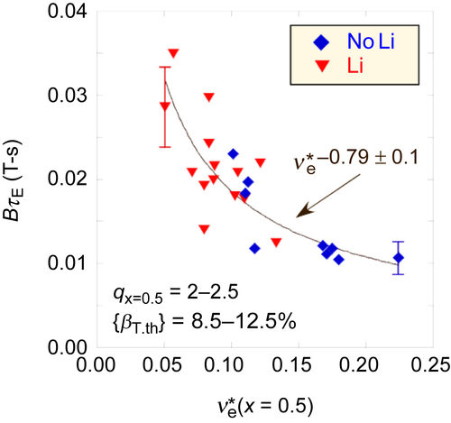
Figure 11.3 Dependence of normalized thermal confinement time (ΩτE ≈ BTτE) for unlithiated and lithiated plasmas within q and βT constraints on electron collisionality at x = (Φ/Φa)1/2 = 0.5, where Φ is the toroidal flux. Reproduced from S.M. Kaye, et al., Nucl. Fusion 53 (2013) 063005, courtesy of IAEA.
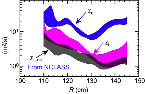
Figure 11.4 Electron and ion thermal energy diffusivity profiles in NSTX H-mode plasmas. The ion neoclassical value is also shown.

Figure 11.5 Local values of βe and νe/I (r/a = 0.6–0.7) for various H-mode discharges. The colored regions illustrate where various microinstabilities are generally predicted to occur. Reproduced from W.G. Guttenfelder, et al., Nucl. Fusion 53 (2013) 093022, courtesy of IAEA.
Microtearing modes, small-scale tearing modes with large toroidal mode numbers, but which are on the ion-gyroradius scale in poloidal extent (kθρs < 1), are driven unstable by electron temperature profile gradients at relatively high collisionality and finite β. The potential importance of microtearing in NSTX was recognized in linear gyrokinetic calculations [29,30], and recent nonlinear gyrokinetic calculations using the GYRO code [31] showed good agreement between experimentally inferred and calculated gyro-Bohm-normalized electron thermal diffusivities in the midregion of the plasma due to microtearing [32,33]. In addition, the calculated diffusivity exhibited a dependence on collisionality consistent with the confinement improvement trend observed in Fig. 11.3, with microtearing being stabilized as collisionality decreased. It was shown that a microtearing-based reduced electron transport model could successfully predict Te profiles for NSTX plasmas in which microtearing modes were calculated to be unstable [34].
At low β and with large electron temperatures and temperature profile gradients due to HHFW heating, electron transport was found to be controlled by ETG modes, which occur on electron-gyroradius scales (kθρs ∼ 10–30) and which are measured by the unique microwave-scattering diagnostic on NSTX. It was found the ETG turbulence increased when the electron temperature gradient exceeded the predicted ETG critical gradient [35,36], and nonlinear gyrokinetic simulations using the global code GTS [37] showed electron thermal diffusivities due to ETG quantitatively agreeing with those inferred from experiment [38,39]. The ETG was further found to be stabilized by reversed magnetic shear, allowing for electron temperature gradients much greater than the critical gradient [40,41], and it was stabilized also by steep density gradients in the plasma edge, such as occurs after an ELM event [42].
The last primary cause of electron transport was hypothesized to be caused by high-frequency (∼ωci) compressional and global Alfvén eigenmodes (CAE/GAEs), which occur in the central region of the plasma. An increase in CAE/GAE mode amplitude was correlated with increased NB heating power, with core electron temperatures that remained nearly constant, but broader Te profiles, even with a tripling of the beam power [43,44]. Assuming classical NB deposition profiles, electron thermal diffusivity values in the center of the plasma of up to 50 m2/s could be reached in the presence of CAE/GAEs, not inconsistent with theoretical estimates based on bursting CAE/GAE activity [44]. Recent work, however, has suggested that the assumption of classical NB deposition may be wrong, as it has suggested that CAEs in the central plasma region can couple to kinetic Alfvén waves (KAW) farther out from the center, effectively producing a channeling of beam energy from the central region to farther out, to the KAW location [45]. This will broaden the beam deposition profile and is consistent with a broadening of the Te profile outside the center and unchanged Te in the center with increasing beam power and CAE activity. Rough estimates indicate a power flow of approximately 500 kW, which could affect the Te by up to 0.5 keV.
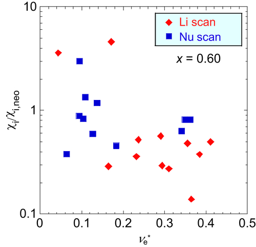
As mentioned previously, prior to NSTX operations, theory calculations led to the expectation that ion transport could be at the neoclassical level under certain circumstances [19]. It was found that with NB heating the ion transport was indeed at the neoclassical level over most of the plasma profile in H-mode plasmas at relatively high collisionality [25,26]. However, as collisionality decreased and electron transport decreased with it, ion transport was found to actually increase to anomalous levels (Fig. 11.6). It is believed that this may be due to the increasing importance of the KBM or other ion-scale microturbulence at lower collisionality.
These results form the basis for developing reduced models of electron and ion transport that can be used to predict performance in an ST-based FNSF. The knowledge base used to accomplish this will expand with the extended operating regime in NSTX-U.

11.3. Macroscopic stability
Because of operation at low toroidal field, STs naturally operate at high-βT and βN, especially with significant amounts of auxiliary heating power. High βT optimizes both fusion reactivity and device cost, and high βN operations optimizes the noninductive bootstrap fraction, with  . Thus, it is important for STs to produce stable plasmas at both high βN (βT) and high κ, the latter parameter being readily controllable. STs are generally designed for high κ (≥2.5). Understanding the macroscopic stability of NSTX plasmas both below and above the no-wall limit necessitated the use of linear and nonlinear ideal and resistive MHD stability calculations. The no-wall limit refers to the β-limit with no nearby conducting wall to provide stabilization. Error fields, neoclassical tearing modes, resistive wall modes, and disruptions all could inhibit achievement of high-β, and these will be discussed in this section, as will the effects of neoclassical toroidal viscosity produced by the application of 3D edge magnetic perturbations.
The highest βT achieved on NSTX was approximately 40%, and this occurred in a discharge whose evolution is shown in Fig. 11.7 [11]. The βT value is corroborated by EFIT equilibrium reconstructions [46,47] and by TRANSP [48,49] calculations. This high-βT value corresponds to βN = 6. The overall MHD stability database [15] is shown in Fig. 11.8, where βN is plotted as a function of li. Several results are noteworthy. βN values up to 7, with βN/li up to 14, were achieved. Discharges with n = 1 active resistive wall mode control (red points) achieve slightly higher βN, βN/li and lower li than those without active control (cyan points). Blue points are long pulse, ≥1 s, plasmas, which are produced using active RWM control. This discharge duration corresponded to current flat-top times up to 40 to 50 times the energy confinement time and up to three to five times the current redistribution time. The database of points indicates a large number of discharges that exceeded the n = 1 no-wall limit (βN/li ∼ 6.7), which is not surprising given both the passive and active stabilization capabilities of NSTX. It is also seen that the βN, βN/li, and li values are within the range expected for both an ST-FNSF and an ST pilot plant.

Figure 11.7 Time evolution of a high-βT discharge. Reproduced from S.M. Kaye, et al., Nucl. Fusion 45 (2005) S168, courtesy of IAEA.

Figure 11.8 High-βN, low-li operational space in NSTX. Red/cyan points indicate plasmas with/without n = 1 active RWM control. Blue circles indicate stable long-pulse plasmas with active RWM control; yellow indicates disruptions. Reproduced from S.A. Sabbagh, et al., Nucl. Fusion 53 (2013) 104007, courtesy of IAEA.
Magnetic islands due to error fields (EFs) naturally occur in tokamaks due to static coil asymmetries as well as dynamic changes in the TF coil with respect to other coils, which are primarily the result of OH × TF forces. Rotation can shield the plasma from EF effects, unless the EF is so large, especially at low density, that it leads to a large island that can lock and result in a disruption. It is critical to determine the EF threshold for locking as a function of density in order to be able to reduce the field below the threshold value through static and dynamic EF control. The ideal perturbed equilibrium code (IPEC) [50], which calculates the shielding currents, ideal plasma response, and the resonant field at the m/n surface has been used to show that including the plasma response is crucial for determining the locking threshold. With this knowledge, the midplane MP coils were used to offset and minimize the effect of the EF-induced islands [12]. Closed-loop feedback for dynamic correction of the OH × TF EF was also employed, resulting in a doubling of the duration that the plasma remained above the no-wall limit.
Neoclassical tearing modes (NTMs), islands destabilized by the helical perturbation resulting from the bootstrap current in the island itself, tend to be more stable in STs than in devices at conventional aspect ratio due to the stronger shaping, high-β and high-q operation, which are stabilizing. It was found that there was decreased susceptibility to NTMs in NSTX as compared to DIII-D [51].
The close-fitting outboard passive conducting shell in NSTX slowed the growth rate of the ideal MHD modes to the much slower timescale of the RWM, which, with passive and active stabilization, allowed the plasma to exceed the no-wall β-limit and approach the ideal (with wall) limit. Active RWM control was accomplished through a feedback control loop using the MP coils to offset the detected mode amplitude and structure. Active control results in significant extensions in pulse length of high-β plasmas.
As the plasma β evolved beyond the no-wall limit, the RWM amplitude grew, and early work suggested that rotation alone could stabilize the mode [52]. However, it was found on NSTX that including kinetic effects in the stability analysis led to a more complete understanding of RWM stabilization physics [53,54]. Enhanced stabilization of the RWM occurs when the plasma rotation is resonant with one of the characteristic kinetic frequencies, such as the precession drift or bounce frequencies. RWMs are more unstable if the plasma rotation falls between these resonances [55]. These predictions were confirmed by measuring the resonant field amplification (RFA) by n = 1 MHD spectroscopy [54]. Fig. 11.9(a) shows the RFA plotted as a function of E × B rotation frequency  , and there is clearly an optimal rotation profile for stable operation (minimum RFA). At that value of
  , the plasma is on resonance with the precession drift frequency. Fig. 11.9(b) shows that on resonance, the RFA decreases with decreasing collisionality (RWM more stable), while there is no change in RFA with collisionality off resonance, also consistent with theory.
It is therefore important to be able to control the plasma rotation profile in order to optimize the plasma stability. The rotation profile near the plasma edge can be controlled by application of 3D MPs, which produce a drag on the plasma. There have been several recent efforts that have extended the initial work on this neoclassical toroidal viscosity (NTV) [56]. Two approaches have been developed [57,58], and they show the importance of collisionality and particle resonances with toroidal rotation, as well as averaging the numerical results over the ion banana width to order to compare to experimental results. Both approaches give reasonable agreement with experiment beyond Ψpol,N ∼ 0.5. NTV is being used as one of the actuators for the rotation control algorithm being developed for NSTX-U.
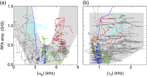
Figure 11.9 (a) n = 1 RFA amplitude as a function of E × B rotation frequency, and (b) n = 1 RFA amplitude as a function of ion–ion collisionality, showing a relatively large change with collisionality at low RFA (“on resonance”) versus almost no change at high RFA (“off resonance”). Reproduced from J.W. Berkery, et al., Phys. Plasmas 21 (2014) 056112, American Institute of Physics.
Major disruptions in tokamaks can lead to halo currents that can exert large, nonaxisymmetric forces resulting in localized stresses that can cause severe damage to PFCs and walls. This is unacceptable in a reactor. Most disruptions are triggered by MHD events, and a large database of NSTX disruption statistics was developed and analyzed in order to gain insight into stable operating space [59]. Fig. 11.10 shows disruptivity as a function of βN, q∗, pressure peaking factor  , shaping factor S = q95Ip/aBT, and li. Disruptivity is defined as the total number of disruptions while the plasma is in a particular operation space divided by the total time it is in that state, and
 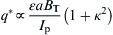 . While no increase in disruptivity was found for increased βn and decreased li, higher disruptivity was found for low q∗, low S, and high Fp and li.
This large database was used to develop a disruption prediction algorithm based on multi-input criteria [60]. Inputs included such parameters as n = 1 RWM amplitude, neutron emission, OH current drive power, and plasma vertical motion, all evaluated in real time. In total, 17 inputs were used to determine maximum disruption detectability while minimizing false positives. A weighted sum of the 17 threshold tests was evaluated every 2 ms for ∼1700 discharges, and a flag indicating an imminent disruption was set when the weighted sum was sufficiently large. Fig. 11.11 shows the histogram of warning times using this method. Ninety-eight percent of the disruptions were flagged within 10 ms, a success rate nearing the ITER requirement. Only ∼6% were false positives. This disruption prediction algorithm will be developed further on NSTX-U.

11.4. Energetic particles
The 3.5 MeV α particles produced in D-T fusion reactions will typically be super Alfvénic, with vα/vAlfvén > 1. Super-Alfvénic α particles can easily excite a variety of Alfvén modes, which in turn can modify the α population through redistribution in energy and space, or through loss from the plasma. Not only will this impact the plasma heating by the α particles, but lost α particles can cause serious damage to plasma-facing components. The neutral beam on NSTX operates with fast-ion energies up to 100 keV, corresponding to approximately three to four times the Alfvén velocity, making NSTX ideal for studying these energetic particle-driven modes and mode–particle interactions. Of particular concern is how the EP modes will affect the ability to provide noninductive current drive by the neutral beam particles, a critical component of fully noninductive discharge scenarios.
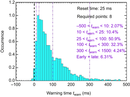
Figure 11.11 Histogram of warning times computed for 1700 disruption discharges. Reproduced from S.P. Gerhardt, et al., Nucl. Fusion 53 (2013) 063021, courtesy of IAEA.
The energetic ions from the NSTX neutral beams can destabilize a variety of toroidal Alfvén eigenmodes (TAEs), with a nominal frequency given by wTAE = k‖vAlfvén = vAlfvén/2qR0, which is in the 50–200 kHz range. There are TAEs that have stationary frequencies, frequencies that chirp up or down, and those whose frequencies chirp up and down simultaneously (“angel-fish”) [61]. There are TAEs that are destabilized near minimum q in reversed magnetic shear discharges (RSTAE), as well those that are modified by finite β (BAEs). In addition, these effects can couple, leading to bursting behavior called “TAE avalanches,” which is associated with sharp, significant drops in the measured neutron rate. Lower-frequency fishbones [62] were also observed in NSTX.
Unique to STs is the presence of high-frequency compressional or global (shear) Alfvén eigenmodes (CAE/GAE), with characteristic frequencies in the range of 0.2–1.2 times the ion cyclotron frequency (ωci ∼ 0.5 to few MHz). As discussed in Section 11.2, the presence of these high-frequency modes is associated with a lack of electron heating at high power in the very core of NSTX plasmas, because of either enhanced electron transport due to these modes and/or channeling of heating power out of the core through coupling with other waves. A spectrogram of various EP-induced magnetic fluctuations is shown in Fig. 11.12 [63].
Fig. 11.13 is an existence plot of types of Alfvén activity seen in NSTX as a function of vfast/vAlfvén and Wfast/Wtotal. Generally, NSTX discharges evolve from the lower right of the figure to the upper left as density increases. TAE avalanches and other energetic particle modes (EPMs) are observed at higher Wfast/Wtotal (low and medium density), while EPMs and quiescent plasmas are seen at lower Wfast/Wtotal (higher densities). TAE avalanches are seen when Wfast/Wtotal ≥ 0.3. The figure also shows that the NSTX-U operational space (gray-shaded region) in these parameters overlaps that envisioned for both ITER and an ST-FNSF. The TAE avalanches and EPMs can result in up to a 35% drop in the neutron rate, which has been determined to be due primarily from energy degradation and spatial redistribution of the fast ions. This conclusion is based on theory simulations of the linear eigenmode structure whose mode amplitudes are constrained by measured displacements, and particle tracking in the presence of these modes [64,65], which indicate a good match between the calculated and measured neutron drops.
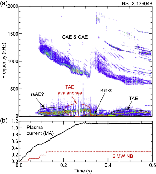
Figure 11.12 (a) Spectrogram of EP-induced magnetic fluctuations in NSTX, (b) plasma current and neutral beam power evolution. Reproduced from E.D. Fredrickson, et al., Nucl. Fusion 53 (2013) 013006, courtesy of IAEA.
In ST plasmas with weakly reversed magnetic shear and qmin slightly above 1, stability calculations [66] indicate that a nonresonant kink (NRK) can be unstable. NSTX discharges have exhibited the coexistence of the NRK with higher-frequency, beam-driven fishbone modes (EPMs), and linear and nonlinear simulations [67] were carried out to study the energetic particle interaction with the NRK [68]. Fig. 11.14 shows the map of mode stability as a function of qmin and βfast/βtotal at fixed input power. At lower qmin, the energetic ions are strongly stabilizing for the NRK (higher βfast/βtotal). At low fast-ion population and low qmin (lower left of the figure), the mode structure (inset) reflects that of a pure MHD mode with zero mode frequency and up-down symmetric structure at zero toroidal angle. At higher fast particle population and higher qmin, the mode transitions to a fishbone-like energetic particle mode with a frequency comparable to the precession drift frequency. The mode structure (inset) has a twisted character. Both the NRK and the fishbone modes significantly affect the fast-ion distribution, reducing the fast-ion density in the central region of the plasma. The results from these linear and nonlinear M3D-K calculations will be used to identify the regimes for stable operation in NSTX-U.
Figure 11.13 Existence space for various types of Alfvén activity in NSTX. Reproduced from S.M. Kaye, et al., Nucl. Fusion (2015) to be published, courtesy of IAEA.

Figure 11.14 Mode stability for the nonresonant kink and fishbone modes in NSTX. Insets show the linear eigenmode structure. Reproduced from F. Wang, et al., Phys. Plasmas 20 (2013) 102506, American Institute of Physics.
The excitation of high-frequency global and compressional Alfvén modes has been studied for an NSTX H-mode discharge using the hybrid-MHD nonlinear HYM code [69]. Corotating CAE modes were calculated to be unstable for a range of toroidal mode numbers, consistent with experimental observations [70]. Results from HYM indicated that unstable CAE modes can strongly couple to KAWs on the high-field side of the torus, as seen by the perturbed magnetic field structure due to the CAE and KAW modes shown in Fig. 11.15. The resonance with the KAW is located at the edge of the CAE potential well, just inside the outer edge of the beam ion–density profile. The importance of this result is that this coupling provides an energy-channeling mechanism for beam energy to excite core CAE modes, with a resulting transport of energy flux away from the magnetic axis to the KAW resonance location; ie, energy flows from the core CAE modes to the mid-radius KAW. As discussed in Section 11.2, estimates of the magnitude of this channeling indicate it could affect the electron temperature profile by as much as 500 eV [45].
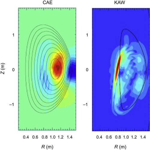
Figure 11.15 Contour plots of the parallel magnetic field perturbation for CAE (left) and perturbed perpendicular magnetic field contours for KAW (right). Reproduced from E. Belova, et al., Phys. Rev. Lett 114 (2015) 015001, courtesy of American Physical Society.
A reduction in GAE/CAE mode severity accompanied application of a δB/B ∼ 0.1–1% n = 3 magnetic perturbation at the plasma edge. Theory simulations indicated a 10–20% reduction in ∂Ffast/∂v⊥, the main driving term for these high-frequency modes. This reduction in mode drive is consistent with the experimentally observed reduction in mode amplitude when the 3D fields are applied [71].
These NSTX results point to a large number of EP-driven MHD modes that, in turn, can impact the fast-ion population and their associated contributions to heating and current drive. Mitigating these effects requires careful control of density, β, and the q-profile, as well as use of applied 3D edge magnetic perturbations.
11.5. Boundary physics
Boundary physics and power-handling issues are challenging in any tokamak device, but even more so in compact STs. Very high peak divertor heat fluxes (≥10 MW/m2) can be reached regularly in NSTX owing to the relatively small major radius (high P/R, P/S) and the relatively short connection length between outer midplane and divertor. This is because of the steep midplane magnetic field pitch, which does not give cross-field transport as much of an opportunity for radial heat spreading. The relatively large mirror ratio and differences in turbulence at low aspect ratio are other properties that could affect the perpendicular and parallel transport in an ST. The physics of the pedestal, boundary, and scrape-off layer plasmas, as well as techniques to mitigate processes causing high divertor heat flux, will be discussed in this section.
The most important and robust operational regime affecting the pedestal profiles is the H-mode, in which edge transport barriers in both density and temperature develop. H-mode discharges with lithium wall conditioning exhibited pedestal profiles that extended to smaller minor radius than those in H-modes with boronization + HeGDC conditioning (Fig. 11.16). Furthermore, lithiated discharges allowed access to the “enhanced pedestal” (EP) H-mode regime. The transition from H-mode to EP H-mode was usually triggered by an ELM [72]. Confinement enhancements in the EP H-mode were up to 50% over and above the already enhanced confinement in lithiated H-modes and reached levels of H98y,2 ∼ 1.25–1.7. Steady EP H-phases lasting over 0.5 s were observed [73]. The EP H-mode was characterized by a region in the plasma edge with very sharp gradients in the ion temperature, typically a factor of three larger than those in the H-phase. There was also a localized region of large rotation shear in the vicinity of the steep ion temperature gradient.

Figure 11.16 Profiles for ne and Te for unlithiated and lithiated discharges (black and red lines, respectively). Reproduced from R. Maingi, (2015), courtesy of IAEA.
A number of different ELM types were observed on NSTX. At low-edge collisionality [74], Type I ELMs, which could result in 5–15% energy reductions due to each ELM, were typically observed. The pedestal stability and excitation of Type I ELMs is consistent with the peeling/ballooning MHD stability model, as implemented in the ELITE code [75], with the pedestal lying close to the peeling-mode stability boundary.
Controlling ELMs is important for reducing the high transient heat loads associated with these events. Lithium application on NSTX ultimately resulted in complete suppression of ELMs, as shown in Fig. 11.17. Type I ELMing discharges evolved into ones with intermittent ELMs and finally into ELM-free discharges with increasing amounts of pre-shot lithium [76]. As the lithium application increased, the main changes at the edge were reduced density in the scrap-off layer and increased electron temperature in the pedestal region. The pedestal width increased, but the pedestal pressure gradient remained the same. This resulted in enhanced total pedestal pressure. An edge-stability analysis using ELITE showed that the unlithiated plasmas that were near the kink-peeling stability boundary moved into the stable regime when lithium conditioning was used, because of the inward shift of the pressure and edge current peak into the reduced magnetic shear region. The ELM-free discharges in NSTX often exhibited impurity and radiation buildup, which were reduced significantly by controlled ELM triggering using applied n = 3 fields [77] or vertical jogs [78].
Particles and heat flow radially out of the plasma and along open field lines into the divertor region. In NSTX, peak divertor heat fluxes reached 10 MW/m2 with 5 MW of injected neutral beam power [79,80]. One of the plasma characteristics determining the level of heat flux is the scrape-off layer heat flux width. This width, which was inferred from IR cameras in the divertor region and mapped back to the midplane, increased with the amount of evaporated lithium but decreased almost inversely with plasma current. The latter two effects can be seen in Fig. 11.18. The variation with plasma current, or Bp, is consistent with the trend observed in a multidevice study covering a range of aspect ratio [81], and it is consistent in magnitude with predictions from a heuristic drift-based model assuming nonturbulent particle transport [82]. The dependence of heat flux width on plasma current is also consistent with results from the XGC1 code [83], which computes the neoclassical and turbulent particle and heat transport.

Figure 11.17 Temporal edge Dα signal for various lithium deposition rates. The regularly occurring spikes represent ELMs.
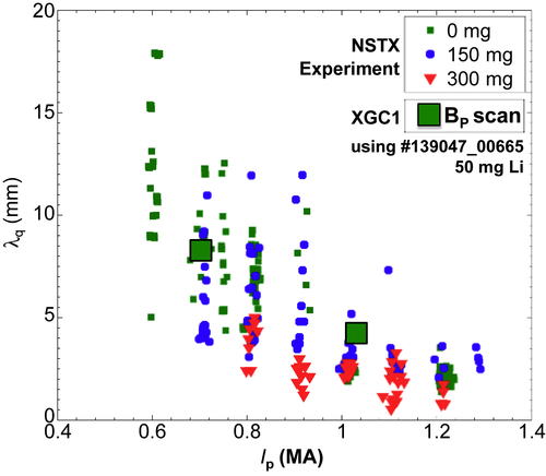
Figure 11.18 Midplane scrape-off layer widths as a function of plasma current for various predischarge lithium deposition rates. The solid rectangles are results from the XGC1 code.
The effect of ELMs on divertor heat flux widths has been studied in NSTX using IR-based 2D surface-temperature measurements coupled to a 3D heat-conduction solver [84]. The results show that under certain circumstances the heat flux footprint during large ELMs could contract by up to 50%, exacerbating the heat flux challenge. Analysis of this data indicates that the heat flux profile broadening or narrowing is directly correlated with the toroidal mode number of the ELMs. The typical range of toroidal mode numbers associated with ELM in NSTX is between one and five [85]. The implications of this result for ITER and FNSF need to be assessed by determining the edge stability and most likely toroidal mode number across a range of expected temperature and density profiles. In particular, scenarios that move the projected operating points up to higher-n stability limits need to be identified in order to reduce the risk of peaking of the heat flux profiles during the ELMs.
Edge and SOL turbulence measurements have been made in order to develop an understanding of the processes controlling the radial transport of heat and particles. A deuterium gas puff imaging (GPI) diagnostic was used on NSTX to obtain detailed edge turbulence information. Camera images from the GPI show strong localized regions of light emission, called “blobs,” in the L-mode plasma, and a much more quiescent edge, with fewer and less-intense blobs, during the H-mode (Fig. 11.19) [86]. In the H-mode, blobs are seen in conjunction with ELM events. The blobs are highly elongated along field lines, ie, are filamentary in structure, and they move both poloidally and radially. Numerical studies were carried out using the SOLT code [87], and the simulations reproduce many features of the GPI measurements, including size and scale-length of the blobs, the direction of their perpendicular flow, and the inferred Reynolds acceleration (Fig. 11.20). The results suggest that the radial penetration of blobs is influenced by flow shear, and thus judiciously driven sheared flows in the SOL could increase the SOL heat flux width if the blobs influence this property.

Figure 11.19 Typical GPI images of the light emission in the NSTX L-mode and H-mode. Also shown is the best estimate for the separatrix location (dashed line) and the shadow of the RF antenna limiter location (dotted line). Reproduced from S.J. Zweben, et al., Phys. Plasmas 17 (2010) 102502, American Institute of Physics.
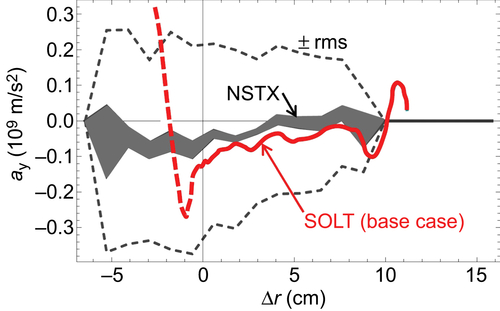
Figure 11.20 Poloidal Reynolds acceleration (ay) for seeded blob simulations (red) compared with experimental results from gas puff imaging (gray). The black-dashed lines represent experimental rms deviations. Reproduced from J.R. Myra, et al., Nucl. Fusion 53 (2013) 073013, courtesy of IAEA.
The high divertor heat fluxes in NSTX generally peaked on the outer divertor, with in–out power ratios of approximately 1:4 [88]. Peak heat fluxes, qdiv,peak, could be reduced by operating in a double-null, rather than the usual lower single-null, configuration, but the most reliable way to reduce the divertor heat flux was through divertor flux expansion, fexp, which is a measure of how much the magnetic flux from the midplane region expands to a larger surface area in the divertor region.
A technique employed on NSTX to expand the divertor flux was to operate in the “snowflake” divertor (SFD) [7] configuration, which is based on having additional field null points close to the usual single null configuration null point. The multiple field nulls make the main X-point region larger, leading to greater flux expansion as seen in Fig. 11.21(a). As seen in Fig. 11.21(b), the SFD configuration alone resulted in a factor of three reduction in the divertor heat flux. Additional heat flux reductions result from operating in a partially detached regime [89,90], achieved by puffing deuterium into the divertor region to reduce the electron temperature to a few eV in front of the divertor plate, thus facilitating enhanced radiative cooling. This effect can be seen in the SFD configuration, also depicted in Fig. 11.21(b), in which the radiative cooling in the partially detached regime decreases the heat flux by an additional factor of three. Lithium coatings of ∼300 mg were also found to reduce peak heat loads by up to 50% [91].
As lithium wall conditioning will be the preferred technique in NSTX-U, with eventual plans to test liquid lithium modules [92], studies have been conducted both in NSTX and in the laboratory to understand the characteristics of lithium surfaces exposed to plasmas and the dependence of properties of lithium coatings on the substrates on which they are deposited. The temperature dependence of lithium sputtering due to impinging deuterium ions was studied both in situ and on a divertor test stand. The in situ measurements were carried out only in a limited range of LLD temperatures, from 100 to 300°C (the melting point of lithium is 180°C). Lithium sputtering yields in atoms/incident D+ for the graphite and unheated molybdenum surfaces (100–150°C) were similar. With heating of the LLDs, and at temperatures above the lithium melting temperature (250–300°C), however, temperature-enhanced sputtering of the surface lithium was observed.
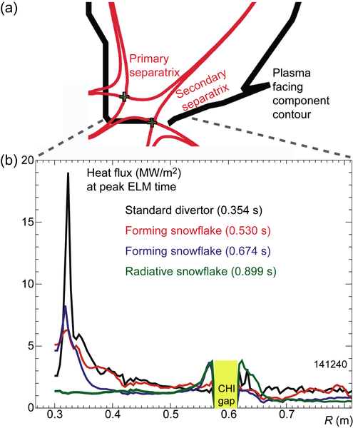
Figure 11.21 (a) Poloidal flux contours for the asymmetric SFD. (b) Heat flux profile during the SFD discharge as labeled. Reproduced from V.A. Soukhanovskii, et al., Phys. Plasmas 19 (2012) 082504, American Institute of Physics.
In order to expand the range of lithium surface temperatures being studied, and to mimic expected NSTX-U divertor conditions, test stand studies of lithium on these metal substrates were carried out on the MAGNUM-PSI linear device at DIFFER [93]. MAGNUM-PSI is a magnetized linear device designed for simulating divertor conditions expected in ITER-class devices, and it can also provide similar densities and temperatures as those found in NSTX. For NSTX-related experiments, a lithium evaporator was installed on MAGNUM-PSI, lithium was deposited onto a molybdenum substrate, and then was subjected to high D+ fluxes. Surface temperatures reached 1300°C in these experiments. While high-incident D+ fluxes onto the target resulted in lithium sputtering yields that increased with lithium temperature up to 400°C and then leveled off up to 700°C, the yields were substantially lower than those measured in low-incident D+ experiments [94]. An intense cloud of lithium was observed directly in front of the target. This intense vapor cloud, which lasted for 3–4 s, resulted in a reduction of current to the target, and this offers the possibility for continuous divertor heat flux mitigation.
Surface science experiments conducted at the Princeton Plasma Physics Laboratory have been performed to understand the mechanisms for D retention in lithium coatings on Mo substrates. The study shows that D is retained as LiD in metallic lithium films. However, when oxygen is present in the film, either by diffusion from the subsurface at high temperature or as a contaminant during the deposition process, lithium oxides are formed that retain D as LiOD. This compound liberates D2 gas at temperatures 100K lower than the LiD decomposition temperature. It highlights the importance of maintaining a metallic lithium layer, as with flowing liquid lithium that constantly replenishes it, at increased power loading and elevated PFC temperatures in future fusion applications.
11.6. Solenoid-free operation and wave physics
Neutron shielding of an inboard, multi-turn OH solenoid in a fusion-energy-producing compact ST design is not possible if it is to remain compact. This is because it would increase the inboard major radius of the plasma, proportionately increasing the overall device size. Thus, it is critical to develop capabilities that will allow for fully noninductive (NI) operation in all ST discharge phases: plasma initiation, current ramp-up, and sustainment. NSTX has explored coaxial helicity injection (CHI) for solenoid-free plasma initiation, and the use of RF and neutral beam drive for NI current ramp-up and sustainment. The processes affecting the fast-ion population and associated neutral beam–current drive were discussed in Section 11.3 on energetic particles. CHI and HHFW physics and results will be discussed in this section.
In CHI, magnetic poloidal flux was injected into NSTX by applying a DC bias voltage and drawing current across two electrically isolated divertor plates [5]. A schematic of the system is shown in Fig. 11.22. During start-up, when CHI is applied, the electrons flow in the toroidal direction since BT ≫ Bp, and thus current is multiplied by the number of toroidal transit times. There is a Jp × BT force that pushes the plasma from the injection region into the main chamber, disconnecting from the electrodes through reconnection. As the poloidal field generated by the toroidal current grows, a closed flux configuration can be formed.
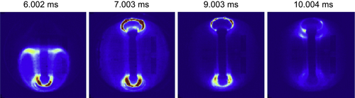
“Transient” CHI was used on NSTX [95]. This was developed on HIT-II and is a variant of CHI in which the injector footprints are close together and the injector current is rapidly reduced to zero. This technique resulted in ∼160 kA of total plasma current with a multiplication factor of ∼70 [96]. The plasma current persisted well after the injection was turned off, reflecting a resistive current decay on closed-flux surfaces. Images of the plasma and closed-flux formation can be seen from a sequence of visible camera images shown in Fig. 11.23. Flux surface closure was corroborated by equilibrium reconstructions and calculations from the axisymmetric Tokamak Simulation Code (TSC) [97–99]; the latter showed formation of closed-flux surfaces as a result of generation of a strong toroidal loop voltage that drives toroidal current. OH induction was applied to a CHI-initiated discharge, and this allowed for currents to reach 1 MA with significantly reduced ohmic flux consumption [100,101]. CHI-generated discharges that were subsequently ramped up in current using induction have also transitioned to an H-mode.
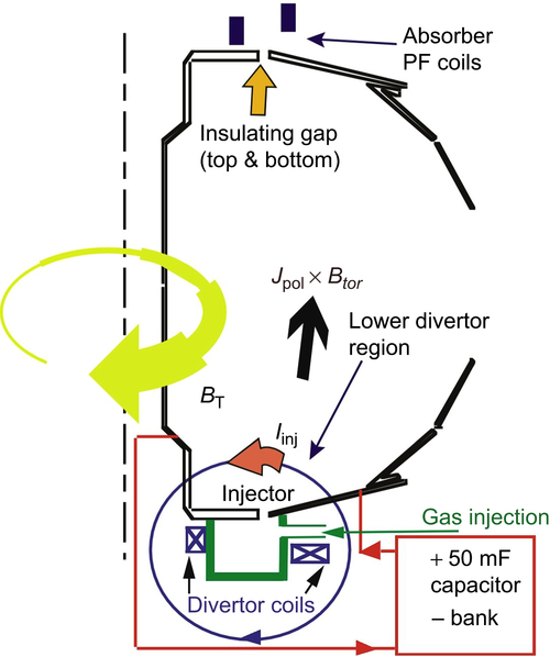
Figure 11.22 Schematic drawing of the NSTX CHI system, including the location of the insulating gaps between the divertor plates. Reproduced from R. Raman, et al., Phys. Rev. Lett. 97 (2006) 175002, American Physical Society.
The underlying physics of CHI start-up has been studied with resistive MHD simulations using the NIMROD code [102] in 2D in order to improve the flux surface closure and current drive using this technique [103,104]. A simplified model, with constant poloidal field currents and time-varying injector currents, was used to study the minimum conditions for flux closure [105]. In these simulations, the injector voltage was adjusted so that the Jp × BT force overcomes the field line tension and open field lines fill the vessel. Flux closure occurred under the right conditions, ie, approximately 0.5 ms after the injector voltage was turned off as in the experiment. The simulations indicate that flux closure is sensitive to electron temperature, rate of voltage drop, and injector flux footprints, in accord with experimental observations. The simulations also show that during X-point formation, the current density is localized to an elongated current sheet whose width scales as η1/2, where η is the magnetic diffusivity. This, along with the computed strong inflow and outflow characteristics, suggests that the X-point formation may be a Sweet–Parker-type [106] reconnection. It is expected that CHI will generate up to 600 kA of start-up current noninductively in NSTX-U.
Conventional RF heating and current drive techniques using electron cyclotron and lower hybrid waves are not practical for STs because of the wave accessibility issues in the overdense ST plasmas, where (ωpe/ωce)2 ≫ 1. Wave research on NSTX has therefore focused on HHFW, which are compressional Alfvén waves but at the 10th–20th harmonic of the ion cyclotron frequency. HHFW was predicted to damp primarily on the electrons with single-pass absorption at high-β. Significant electron heating was observed in NSTX, with Te0 ∼ 6.2 keV in helium and ∼5.2 keV in deuterium with 3 MW of HHFW (Fig. 11.24) [107]. The very peaked Te profile in Fig. 11.24 reflects the very-peaked HHFW heating profile. The precise determination of the actual HHFW heating power coupled to the main plasma could be determined from changes in the plasma-stored energy when the HHFW was pulsed on and off, with heating efficiencies ranging from 40% to 80%, with the lower efficiencies at higher wave phase velocities (lower wave number k‖) [108]. Despite the loss of heating power coupled to the core plasma, HHFW could drive significant fractions of current noninductively through direct current drive and through enhancement of bootstrap current through electron heating. For a 300 kA discharge with HHFW, the plasma loop voltage was seen to decrease to zero, and approximately 70–100% of the current was calculated to be noninductive.
The HHFW power not coupled to the plasma is lost along open field lines in the SOL, as confirmed by visible images (Fig. 11.25) [109]. The power loss was found to be higher at higher density, indicating a possible relation between the power losses in the SOL and the fast-wave cutoff. Understanding the physics of RF deposition and especially this loss mechanism will lead to discharge optimization where RF losses can be minimized, and can also aid in the projection of ICRF efficiency and deposition in ITER. Full wave simulations using the AORSA code [110] have been performed to demonstrate the direct correlation between the location of the fast-wave cutoff relative to the antenna and the last closed flux surface (LCFS), the large amplitude of RF fields in the SOL, and the power loss there [111]. The simulations predicted increased power losses to the SOL with increasing density in front of the HHFW antenna, in accord with experimental observations. This dependence was found to be related to the wave propagation characteristics with respect to the position of the fast-wave cutoff. At low density, the cutoff is in front of the HHFW antenna (low power losses), while at high density, the cutoff “opens up” and no longer exists in front of the antenna (high power losses). This transition density increases with increasing magnetic field, indicating that HHFW losses to the SOL will be low over a wider range of density in the higher toroidal field NSTX-U.

Figure 11.24 (a) Te (R) immediately prior to HHFW heating (dashed-blue line) and during 2.7 MW of kf = −8 m−1 heating (solid line) of a helium plasma. (b) same for 3.1 MW of HHFW heating in a deuterium plasma. Reproduced from G. Taylor, et al., Phys. Plasmas 17 (2010) 056114, American Institute of Physics.
11.7. NSTX-Upgrade
The NSTX-U [18] has three overarching research goals:
1. To explore the unique ST-parameter regimes to advance predictive capability for ITER and beyond. In order to address this goal, NSTX-U will access reduced collisionality (up to a factor of three to six lower than on NSTX), and high-β (βN ≤ 6) with an ability to vary the q and rotation profiles for enhanced stability, confinement, and noninductive current drive. Models for thermal and fast-ion transport will be developed and/or tested.

Figure 11.25 Visible camera image of HHFW power interaction with the edge plasma and resulting heat spirals on the upper and lower divertors. Reproduced from R. Perkins, et al., Phys. Rev. Lett. 109 (2012) 045001, American Physical Society.
2. To develop solutions for the plasma–material interface (PMI). High-heat fluxes, with qpeak up to 40 MW/m2 and Pheat/S ∼ 0.5 MW/m2, which is up to five times greater than on NSTX, will need to be mitigated.
3. To advance the ST concept for a fusion nuclear science facility. Achieving this goal requires demonstrating 100% noninductive sustainment at a performance level that extrapolates to ≥1 MW/m2 neutron wall loading in FNSF, as well as developing noninductive start-up and ramp-up techniques for an FNSF with small, or no, solenoid. The latter is a unique requirement for an ST-based FNSF.
A major motivation for the upgrade is to access lower-collisionality plasmas, which is important for extrapolations of confinement, stability, and noninductive current drive. As an example, Fig. 11.26 shows the normalized confinement time as a function of collisionality (based on Fig. 11.5 but with a logarithmic abscissa to make more obvious the low-collisionality values relevant for an ST-based FNSF). As can be seen, the strong inverse collisionality dependence of confinement seen on NSTX extrapolates to about a factor of two higher value than for the ITER98y,2 scaling, in which the collisionality dependence is weak. NSTX-U will achieve a factor of three to six reduction in collisionality in order to assess further this dependence, which could have a significant impact on the design of an ST-FNSF.

Figure 11.26 Normalized confinement time as a function of normalized collisionality. Data shown are from NSTX.
As collisionality is lowered, it is expected that the dominant turbulent modes affecting plasma transport may change. While ETG modes that can drive electron transport show little dependence on collisionality [33], microtearing modes may be suppressed at low collisionality. However, KBM and TEM modes, both of which can cause both electron and thermal ion transport, may become more important. As discussed in the macroscopic stability section, RWM stability and NTV can be strongly dependent on collisionality, with RWM stability enhanced at lower collisionality with certain rotation profiles. Noninductive current drive can also benefit from reduced collisionality through optimization of both bootstrap and neutral beam–driven currents.
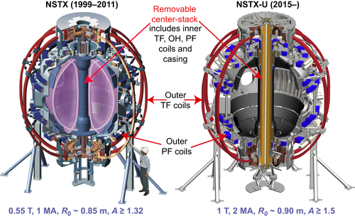
In order to obtain the reduced collisionality, NSTX-U will allow for a factor of about two increase in plasma current and toroidal magnetic field to values of 2 MA and 1 T, respectively. A major upgrade component is a new center stack that is slightly larger than that in NSTX, and this will result in plasmas with slightly higher aspect ratio (R/a = 0.95/0.55 m = 1.7) and elongation (κ up to 2.8) than in NSTX. The center stack will provide three to four times the ohmic flux swing as that in NSTX for inductive operation, and, coupled with predicted bootstrap and beam-driven noninductive currents, will allow for pulse lengths up to 5 s [112,113]. A comparison of NSTX and NSTX-U cross-sections is shown in Fig. 11.27.
A second major upgrade is the addition of a second neutral beam, which will inject more tangentially than the first beam. Not only will this second neutral beam provide higher auxiliary heating power to access reduced collisionality, but it provides the means, through use of different combinations of the total of six beam sources, to vary and control both rotation and q profiles, both of which are important for optimizing confinement [114], stability [53], and noninductive current drive [112,18].
Other capabilities for NSTX-U include a continuation of using transient CHI, which is projected to provide up to 600 kA of noninductive start-up current at the higher toroidal field; 600 kA is sufficient to confine fast ions from NBI for heating and current drive purposes.
Wall conditioning using boronization + HeGDC or lithium conditioning, the latter using the present two downward-pointing LITERs and eventually two additional LITERs pointing upward, will be employed. High-Z tiles will gradually be introduced into the NSTX-U divertor regions to assess the high-Z impurity transport and power-handling capabilities as a possible PMI solution. High-Z PFC research will benefit both ITER operations and an ST-FNSF design. The high-Z divertor tiles would serve as substrates for novel liquid-lithium divertor modules, also to be tested on NSTX-U. If the high-Z divertor tiles prove to benefit PMI solutions, there is consideration for changing all PFCs to high-Z materials.
High-flux expansion snowflake or X-divertors, coupled with radiative detachment, will be employed for mitigating the high-heat fluxes expected on NSTX-U. Additional PF coils in the new center stack will enable operation with both upper and lower snowflake divertors. Simulations for NSTX-U plasmas using the multi-fluid UEDGE [115,116] show a 70% reduction in divertor heat flux in a detached snowflake divertor configuration, with detached conditions extending down to relatively low density. Additional methods of heat flux mitigation being considered include strike point sweeping and lithium vapor shielding, the latter being studied on the Magnum-PSI divertor test stand [93].
Additional capabilities being considered for future upgrades include up to 1 MW of ECH, a cryopump and a set of off-midplane magnetic perturbation coils. The ECH would be used for heating start-up plasmas in order to increase coupling to HHFW and NBI for optimizing current drive [113]. The cryopump, planned for the lower divertor region, would be used for particle and density control, critical to maintaining high performance in longer-pulse discharges. Other particle and density control methods to be tested include ELM pacing with applied magnetic perturbations or a lithium granule injector [117]. The precise design of the off-axis nonaxisymmetric control coils and the resulting poloidal field spectrum is being optimized with respect to several metrics, including control of error fields and rotation, resonant magnetic perturbations for ELM control, and active resistive wall mode control.
As the ability to achieve fully noninductive operation is one of the overarching goals of NSTX-U, simulations to develop these scenarios at 1 T have been carried out. The simulations assume noninductive start-up currents of several hundred kiloamperes, and include HHFW, NBI, and bootstrap drive mechanisms. These time-dependent simulations were carried out with the free boundary equilibrium solver ISOLVER in TRANSP, and have pointed out the importance of the availability of EC heating of CHI-initiated plasmas in order to raise the electron temperature and enhance the coupling of the start-up plasma to both HHFW and NBI. An example of such a time-dependent simulation, which was run with loop voltage constrained to zero, is shown in Fig. 11.28. TORAY [118] simulations indicate that 1 MW of EC heating can rapidly heat start-up plasmas from Te ∼ 10–20 eV, typical of CHI conditions, to about 1 keV in 30 ms. Up to 4 MW of HHFW is then used in conjunction with EC to further heat the plasma, as calculated by TORIC [119], and to drive current to facilitate NBI with minimal fast-ion losses. The combined EC/HHFW can sustain a noninductive current of 350 kA. With 10 MW of NBI distributed over the two beamlines, the simulation shows that the current can be ramped up noninductively to 900 kA in 2.5 s. With the density between 60% and 90% of the Greenwald limit and H98y,2 ∼ 1.0–1.2, the total current is sustained with a contribution from the bootstrap of between 40% and 60%. These simulations offer a roadmap for attaining the unique ST requirement of fully noninductive operation.

..................Content has been hidden....................
You can't read the all page of ebook, please click here login for view all page.