12.2. Key scientific achievements of 15years of MAST research
Together with NSTX (see Chapter 11), MAST has moved the ST research into the domain of hot and dense plasmas. Core temperatures of Ti≈3keV and Te≈2keV have been achieved simultaneously in L-mode plasmas with core densities ne≈3× 10¹⁹m−3 at Ip=1.2MA even with moderate heating power [26]. This enabled strong contributions to the three main pillars of research on MAST: ITER and DEMO physics, future ST concepts and basic science.
12.2.1. Plasma confinement
Optimising plasma confinement at a given plasma current and toroidal field is the prime goal for any magnetic confinement fusion device, and the plasma confinement on MAST is very similar to the confinement observed in conventional aspect ratio tokamaks. In tokamaks three main confinement regimes are encountered: the Ohmic regime for plasmas only heated by the toroidal current; the low-confinement L-mode where the auxiliary heating increases cross-field transport, and the high-confinement H-mode, where a transport barrier at the plasma edge forms. Future tokamaks aim to operate in H-mode, although the steep pressure gradients building up in the region of the transport barrier lead to periodic relaxation by edge-localised modes (ELMs). On MAST ELMy H-mode is routinely achieved at moderate input power. The energy confinement is generally in agreement with the international ITER (98,y2) scaling HH=τE/τEITER(98,y2)≈1 [27,28]. With low ELM frequency HH≈1.5 has been observed [27]. Typical confinement times for Ip=0.8MA MAST discharges are of the order of τLE≈25ms for L-mode and τHE≈40ms for H-mode. The tight aspect ratio design, enhancing neoclassical effects, and the strong rotation, however, lead to some interesting differences for the core confinement. In this section we will first discuss the access to H-mode and then discuss energy, particle and momentum confinement.
12.2.1.1. Access to high confinement (H-mode)
Above a certain ion heat flux [29] a transport barrier forms at the plasma edge (ETB) and H-mode is accessed. The factor two improvement with respect to L-mode makes H-mode the preferred operation scenario for future tokamaks. Despite being known since 1989 [30], key aspects of the basic physics understanding are still missing and no predictive theory exists, though it is widely accepted that turbulence suppression by sheared E×B flows is a key ingredient and is ultimately what sustains the H-mode.
Within the first month of its operation H-mode was accessed on MAST in Ohmic and NBI heated (PNBI<2MW) plasmas [31–33] allowing detailed studies of the ETB formation. A power threshold as low as Pthr=0.6MW was measured in Ohmic discharges after fresh wall conditioning with boronisation. Empirical scaling of Pthr to future devices – important to determine the auxiliary power needed to access a burning plasma regime – has large uncertainties since there are many hidden parameters. In particular, ways to reduce the power requirements may reduce the costs of a fusion power plant significantly since auxiliary heating systems are expensive and would only be needed for starting the fusion burn process.
There are several factors that strongly influence H-mode access on MAST. The L to H transition is very sensitive to the closeness to an exact DN configuration [34]. Pthr is increased by more than a factor of two by shifting the plasma only a few centimetres off the exact DN configuration into lower SN configuration. This separates the flux surfaces going through each of the two X-points at the outboard midplane by the order of Δrsep≈1cm1 with little effect on the kinetic profiles apart from the inner scrape-off layer (SOL). Routine low-power H-mode operation in lower SN with the favourable ion ∇B drift direction toward the X-point is possible in plasmas where the magnetic axis is shifted down by ΔZ≥0.1m. This highlights another sensitivity on the vertical height of the X-point [35,36]. Routine H-mode operation in upper SN has not been achieved consistently. The strong effect of the closeness to DN has also been observed on NSTX and the conventional tokamaks ASDEX Upgrade [37] and EAST [38]. The effects of divertor configuration on H-mode access is currently an active research field on many tokamaks [39–44]. There is no fundamental understanding of these strong effects on Pthr with relative small changes to the magnetic configuration, though changes in the SOL profiles may well be a reason for the changes observed with the divertor configuration [44,45]. The understanding of the effect of the divertor and recycling on H-mode access is in particular important, since it might lead to a lower Pthr on ITER.
A further contributor to easier H-mode access is the high-field-side (HFS) fuelling [46]. This effect has been initially observed on COMPASS-D [47] but is much more pronounced in MAST [48]. The reduction of Pthr has been attributed to changing Pfirsch-Schlüter flows in edge plasma from the localised fuelling source [49,50]. As on DIII-D [51], H-mode on MAST can also be initiated by a density wave from a pellet [52]. Since future fusion devices rely on pellets for fuelling, H-mode access may be aided by the fuelling method.
A key question that remains is what physics triggers the transition. To answer this measurements on the time scale of the turbulence quenching of 100−200μs are needed. Profiles of Te, ne and Er through relatively fast Δt<2ms transitions with a time resolution of Δt≤0.2ms show no changes in neither values nor gradients before the L-H transition [36] (see Figs 12.3 and 12.4). After the transition, |∇Er| and |∇ne| increase with characteristic times of about τ≈0.6ms whilst the profiles change on a few ms time scale. Even faster measurements of the poloidal and toroidal He+ velocity – a marker for Er – with Δt=20μs in Pthr studies during a density scan reveal a 4−5kHz limit cycle like oscillation before the L-H transition with ∇Er changing together with the reduction of turbulence at the beginning of the cycle, but filaments already being expelled whilst ∇Er is still high at the end of the cycle [53,54] (see Fig. 12.4). The interplay between the sheared flows and turbulence are key to a basic understanding of the transition physics.
Figure 12.3 Evolution of (a) ne and (b) Te through various L-H transitions as well as Er (c) through an L-H transition and (d) through an ELM. From H. Meyer, et al., Nucl. Fusion 51 (2011) 113011, Copyright from CCFE.
Figure 12.4 Conditionally averaged (a) poloidal and (b) toroidal He+ flow measurements with respect to (c) the conditionally averaged Dα emission during a limit cycle. From H. Meyer, et al., Nucl. Fusion 53 (2013) 104008, Copyright from CCFE.
In the framework of the control of the ELM (discussed in Section 12.2.2) the impact of resonant magnetic perturbations (RMP) on the L-H transition has been studied in MAST [55,56]. Generally, RMPs lead to a more positive Er close to the separatrix and Pthr is increased, but a nonmonotonic behaviour with toroidal mode number n is observed [55]. On MAST the n=4 perturbations affect the transition the least. On ITER, RMPs are a key technology to control the ELM power loads (Section 12.2.2) even for the first ELM, and minimising the effect of this control technique on H-mode access increases the margin of ITER operation.
12.2.1.2. Energy confinement
Though understanding of turbulent transport in tokamaks has improved greatly over the years, we are still far from predictive first principle modelling of future devices, in particular for STs, and rely on empirical scalings of the energy confinement time τE. The data at low aspect ratio and high β will help to improve the scalings by expanding the parameter space. For future STs the scaling of τE in H-mode with collisionality is the most important, as this requires the furthest extrapolation. This is one reason to increase Ip and Btor as well as the heating in MAST-U (see Section 12.3).
In heated plasmas without the ETB (L-mode) the energy confinement on MAST is underestimated by the L97 scaling [57], suggesting a more positive dependence on aspect ratio. The scaling with plasma current τE∝I0.96p of the L97 scaling was confirmed during a dedicated current scan at constant density. At Ip=1.2MA, the core Ti and Te reached 3 keV and 2keV, respectively, for an injected power of PNBI<2MW [26]. In H-mode τE seems to roughly align with the multi-machine ITER98(y,2) scaling. Regression of MAST data alone in terms of engineering parameters as well as dedicated scans, however, support a weaker scaling of τE with Ip and a stronger scaling with BtorτE∝I0.59pB1.4tor [58,59]. In terms of dimensionless parameters this translates to a weaker scaling with safety factor, q, and a stronger scaling with collisionality BτE∝ν−0.82±0.1eq−0.85±0.2[59] (see Fig. 12.5).
This scaling gives a more favourable extrapolation to future STs, but at low collisionality the dedicated scans seem to deviate from the stronger scaling (see Fig. 12.5(a)). Gyrokinetic nonlinear local (GS2) and global (GYRO) microstability simulations show that ion temperature gradient (ITG) modes in this collisionality range are suppressed, but electron scale turbulence driven by ∇Te (ETG) and ion scale microtearing modes (MTMs) are unstable [59,60]. The collisionality dependence of the MTMs is unlikely to be strong enough to explain the scaling, but in the GS2 simulations of electron scale turbulence it is found that at fixed temperature gradient the electron heat transport decreases with collisionality. Hence, in H-mode ion heat transport seems to play less of a role than electron heat transport for confinement, and the ion heat diffusivity is often close to the neoclassical prediction [46,61].
In L-mode ITGs are found to be unstable and ion heat transport is found to be 4−10 times the neoclassical value. Under the right conditions internal transport barriers are easily formed [62,63]. The common access criteria developed for conventional tokamaks ρ∗Ti,e=ρs∂Ti,e/∂R>ρ∗ITB≈0.014 is exceeded on MAST even for discharges where transport analysis shows no sign of a transport barrier. Measurements of the ion scale density fluctuations using beam emission spectroscopy (BES) [64] in L-mode show that the turbulence is critically balanced [53,65], that is, exhibiting comparable time scales for drift-wave drive, parallel streaming, magnetic drift and de-correlation of the fluctuations. In the gradient region (0.4<r/a<0.8) the turbulence de-correlation times, τc are found to be always shorter or comparable to 1/γE, with γE the perpendicular E×B shearing rate. Assuming a Boltzmann response of the density fluctuation δn/n≈eϕ/Te (ϕ, plasma potential), the BES measurements also allow an estimate for the time scale associated with the advection of the fluctuations, τNZnl, excluding zonal flows [65]. A correlation of τc/τNZnl∼ν0.8±0.1∗,i is found, hinting at the presence of ion scale zonal flows as a possible mechanism regulating the turbulence on MAST [65]. Measurements of velocity fluctuations are currently not able to confirm directly the zonal flows but are consistent with their presence [66]. BES data have also been used for direct validation of global gyrokinetics of turbulent transport in MAST [67] (eg, using the particle in cell code NEMORB).
Figure 12.5 Scaling of the energy confinement time with (left) electron collisionality and (right) safety factor in dedicated dimensionless scans. The upper panels show the small variation of the other relevant parameters. From M. Valovič, et al., Nucl. Fusion 51 (2011) 073045, Copyright from CCFE.
Even in regions where finite flow shear would suppress ITG turbulence (eg, at zero magnetic shear) the normalised ion temperature gradient, R/LTi=R∂lnTi/∂R might still be limited by so-called subcritical turbulence. This turbulence is excited above a critical R/LTi predicted to conform to a surface in (γE, q/ε) referred to as zero-turbulence manifold [68] (ε=a/R=A−1: inverse aspect ratio). On MAST the observed scaling of R/LTi and the turbulent heat flux with γE and q/ε is qualitatively consistent with this prediction [69] suggesting that such turbulence limits the achievable ion temperature gradient in MAST. The zero-turbulence manifold has two implications. On the one hand, by increasing the ratio of poloidal to toroidal magnetic field, as in low aspect ratio devices, ion energy confinement can be improved at any nonzero value of γE. On the other hand, at fixed q/ε there is an optimal flow shear at which the maximum ion temperature gradient is achieved. Being able to predict the optimum γE (q/ε) may allow the improvement of core confinement in particular in future STs.
On MAST, discharges have also been run with NBI antiparallel to the plasma current (cntr-NBI). Due to the unfavourable fast particle confinement about two-thirds of the beam energy is lost by prompt orbit losses. Interestingly the stored energy in these discharges has been comparable to similar discharges with the normal NBI parallel to the plasma current (co-NBI) [28,61,62]. With cntr-NBI the radial electric field due to the torque input and prompt losses augments the Er due to the pressure gradient and leads to a higher rotation shear, which may be the explanation for the two-times-higher confinement observed in these plasmas. The transport analysis shows that the ion diffusivity is well above the neoclassical diffusivity [28]. With cntr-NBI, also H-mode-like states have been observed with ELM-like events and a clear transport and Er bifurcation, but little evidence for a pedestal [70]. These studies are important to understand the interplay between flow shear and plasma transport, in particular for a CTF, where strong plasma rotation is expected.
12.2.1.3. Particle confinement and fuelling
MAST has a large tank volume. The neutral gas buffer in this volume dominates the fuelling, in particular fuelling by LFS gas puff. For such plasmas the particle confinement on MAST has been analysed using a 0D global particle balance [71], estimating typical ion particle confinement 10ms≤τp,I≤100ms [72] with a fuelling efficiency of 10%. A strong anticorrelation of τp,i∝n−0.7D2 with the neutral density in the tank is found. The wide range of variation suggests a genuine change in particle behaviour with increasing tank gas density. This is also observed in estimates of the energy confinement time at high density. Good particle control with a large tank volume can only be achieved with a baffled divertor chamber and fuelling from the divertor, the HFS or with pellets [71] as foreseen in MAST-U (see Section 12.3). The walls on MAST act as particle sinks throughout the discharge if conditioned by 4He glow discharge cleaning or boronisation, and in most discharges more than 80% of the inventory is retained in the walls [73].
Increasing the density in a fusion device will increase the fusion product, as the optimum ion temperature for a fusion plasma is fixed by the fusion cross-section and readily achieved in large fusion devices such as JET. An empirical ‘soft’ density limit, the Greenwald density nG=1014Ip/πa2 has been established on conventional tokamaks.2 In L-mode MAST has operated at n¯e≥1.8⋅nG, well above this limit [74] (see Fig. 12.6), both with fuelling by gas or pellet. In high-current H-modes n¯e≈1.2⋅nG was reached for 20ms, but only with pellet injection. Deep pellet injection can increase the fuelling efficiency dramatically, and up to 75% efficiency has been estimated for Ohmic discharges without H-mode. With NBI the fuelling efficiency decreases.
Figure 12.6 Early operating space on MAST in line-averaged density normalised to the Greenwald density and plasma current. Highlighted is the trajectory of a pellet-fuelled H-mode discharge. From R.J. Akers, et al., Phys. Plasmas 9 (2002) 3919, Copyright from CCFE.
Figure 12.7 Pellet retention time as a function of pellet penetration. From M. Valovič, et al., Nucl. Fusion 48 (2008) 075006 (8 pp.), Copyright from CCFE.
Of particular interest for future devices is the pellet retention time in H-mode with shallow pellet injection, eg, pellets on ITER will ablate within ρpel>(0.8–0.9). The pellet retention time decreases stronger than expected from diffusion alone with normalised pellet penetration and depends on the state of the edge transport barrier (see Fig. 12.7). The interaction of fuelling pellets with ELMs controlled by RMPs (see Section 12.2.2) is found to be rather modest, which is favourable for ITER [76,77]. These data are key for sizing the pumping system in future devices relying on pellets as their main fuelling method.
12.2.1.4. Momentum transport
Turbulent transport and plasma stability are strongly influenced by plasma rotation. Neutral beam driven future STs (eg, CTFs) are expected to have strong toroidal rotation due to the high torque from the beams, whilst ITER and DEMO rely on intrinsic rotation lacking momentum sources. It is important to understand the toroidal rotation profile in a tokamak. Momentum transport in L-mode on MAST is strongly linked to the ion energy transport and the data is generally in agreement with a Prandtl number Pϕ=χϕ/χi≈1 in the core [58]. Only toward the edge a reduction of Pϕ is seen supporting the presence of a momentum pinch by the so-called Coriolis drift [78]. The poloidal rotation in the core is found to be in agreement with neoclassical predictions [79].
Measurements of the density dependence of the intrinsic rotation in Ohmic discharges [80] using a Doppler backscattering diagnostic [81] reveal a reversal of the core rotation from co-current to counter-current above a certain threshold in n¯e/Ip (see Fig. 12.8). This data supports the model that collisionality-dependent neoclassical corrections to the ion distribution function alter the turbulent momentum transport [82]. ITER and DEMO rely on the mechanisms of intrinsic rotation to build up a strong enough rotation to suppress certain stabilities, and the validation of basic theory is of particular importance.
12.2.2. Pedestal and ELM physics
As mentioned in the previous section, the H-mode with its edge transport barrier (ETB) is currently the most attractive regime for future fusion devices. The reduced transport in the ETB leads to steep gradients in density, temperature and therefore in pressure. Turbulent core transport is often stiff, meaning that a critical gradient length exists that cannot be exceeded. The ETB then produces a pedestal at the plasma edge, increasing the global confinement. Unfortunately, the steep pressure gradient in this pedestal is prone to a periodic relaxation by so-called edge-localised modes (ELM).
The ELM is one of the key limiting instabilities for ITER and all future devices operating in H-mode, due to the high transient heat loads at the divertor target plates. For ITER at Ip=15MA – needed to achieve Q=10 – predicted ELM energy fluence is about a factor of four above current material limits. In order to allow the operation in H-mode for future devices a fundamental understanding of the instability itself as well as the evolution and transport in the pedestal are needed in order to avoid or control the ELM.
Visible imaging from MAST was instrumental to understand the dynamic and structure of ELMs [83]. The large field of view and the large LFS field line angle of 20−30 degrees on MAST allow a unique insight into ELMs as the instability grows unimpeded by walls or structures into the gas buffer. Diagnostics with high spatiotemporal resolution in the edge pedestal region and the divertor allow an accurate description of the plasma through the ELM cycle. In vessel perturbation coils enable control of the instability. The papers by Oyama et al. [84]. and more recently by Kirk et al. [85] give a good overview of the current knowledge of ELMs encountered at highest pedestal pressures, pped.
Figure 12.8 Measurements of the intrinsic rotation in Ohmic discharges with Doppler backscattering at midradius. Shown are (a) the scattered electric field spectrogram, (b) the line averaged density and (c) the (black diamonds) measured and (red line) predicted rotation at midradius. From J. Hillesheim, et al., Nucl. Fusion 55 (2015) 032003, Copyright from CCFE.
12.2.2.1. The ELM crash
The imaging of the filamentary structure of the ELM (see Fig. 12.9(b)) helped tremendously to understand the ELM crash [83], although the filamentary character of the ELM had been measured before [87,88]. Analysis of the fast videos allowed to determine the dynamics of the ELM crash. There are several types of bursty edge instabilities named ELMs that have been found in H-modes on tokamaks depending on the edge conditions [87]. At low input power above the H-mode threshold power type-III ELMs are found decreasing in frequency with increasing input power, associated with lower achievable pped. As the power is increased the confinement and the achievable pped increases, leading to type-I ELMs. The frequency of type-I ELMs increases with increasing power. Type-I ELMy H-mode is the standard operating regime foreseen for ITER. With higher shaping close to double null, at high collisionality very small ELMs occur. These type-II ELMs originate at the bottom of the pedestal [89] and on MAST co-exist with type-I ELMs at only slightly lower pped. Other types of ELMs have not been observed on MAST. Only for the type-I ELM the underlying instability has been identified [90]. The structures of type-I and type-III ELMs show no significant difference, whilst the structure of the type-II ELMs is fundamentally different [58,91]. The different ELM regimes on MAST can be distinguished in terms of pedestal parameters [58,92]. At high collisionality (Tpede≤0.15keV,npede≥2.5⋅1019m−3) type-III ELMs exist. At lower collisionality (Tpede≥0.15keV,npede≥2.5⋅1019m−3) these transit into type-I ELMs, whilst also a low-density branch of the type-III ELMs exists (Tpede≥0.1keV,npede≤2⋅1019m−3), initially called type-IV ELMs sitting on the same isobar in Tpede and npede as the high-density type-III ELMs. Due to the high-heat loads connected with type-I ELMs (Section 12.2.4) the smaller natural type-II ELMs with good confinement may be the more attractive regime for a fusion power plant, but this regime may not extrapolate to ITER, DEMO or future STs at lower collisionality. Type-III and type-IV ELMs also have acceptable heat load, but due to the lower pedestal pressure give lower confinement.
Figure 12.9 Filamentary structure of an ELM (a) modelled using the JOREK code compared to (b) an image from the fast visible imaging. From S.J.P. Pamela, et al., Plasma Phys. Control. Fusion 55 (2013) 095001, Copyright from CCFE.
For type-I ELMs multiple (typically n≈4–17) toroidally rotating fingers first grow from the separatrix outward until one or more filament stops and detaches from the main plasma [26,93–96]. The filaments accelerate radially outward from the plasma, reaching velocities of the order of 1–2km/s. The density perturbation from BES in the early 20μs of the 100–200μs ELM crash are shown in Fig. 12.10(a)
Figure 12.10 Density perturbation measurements using BES: (a) the filament motion during the ELM crash measured by the BES during the 20μs across an ELM crash in a MAST H-mode plasma; (b) the evolution of the density perturbation of the precursor mode prior to an ELM crash measured across 50μs before the ELM crash occurs in a MAST H-mode plasma. The dashed line shows the position of the separatrix. From I. Chapman, et al., Nucl. Fusion 55 (2015) 104008, Copyright from CCFE.
rotating in the ion diamagnetic direction [60]. Different filaments detach from the main plasma at different times, but ultimately all filaments are expelled. The electron density and temperature in the ELM filaments have been characterised using Thomson scattering [97]. The bulk of the energy is lost during the rise phase of the ELM, whilst the filaments are still close to the separatrix [94] and only a fraction of the energy (∼2.5% per filament) is transported radially to the wall [98,99]. During the rise of the ELM the sheared flow at the edge due to the radial electric field is destroyed but quickly recovers after the peak of the ELM (see Fig. 12.4(d)) [36,54,100]. The small type-II ELMs display a regular n≈20–30 structure with only a few filaments detaching from the main plasma [58,89]. For type-I ELMs often a clear precursor is observed rotating in the electron diamagnetic direction [58,60,85,97]. The density perturbation of this precursor is shown for 50μs of this 200–300μs lasting phase in Fig. 12.10(b).
The filamentary nature of the ELM is also apparent on the strike points, where a spiral pattern is observed with visible imaging [94]. In the heat load profile the spiral pattern can only be measured in the outer wing of the profile far away from the strike point [94,101]. A simple model of the mostly convective ELM energy loss agrees well with data from MAST [94] and ASDEX Upgrade [98] (see Figs 12.11 and 12.12). For type-I ELMs the fractional ELM energy losses increase with decreasing collisionality and can reach ΔW/W≤15% for the lowest collisionality ν∗e≈0.03 with pedestal temperatures in excess of Tpede≥0.4keV[94]. During the ELM crash there is evidence from electron cyclotron emission that transient parallel electric fields generate highly superthermal electrons [102].
On MAST the highest heat load at the targets during an ELM is always observed at the LFS strike points [101,103]. With respect to the inter-ELM period the balance of energy flowing to the different strike points changes. In SN the ratio from the inner strike point to the outer strike point shifts from Ein/Eout≈0.15 inter-ELM to Ein/Eout≈0.3 during the ELM. This is in contrast to conventional tokamaks where higher power loads on the inner strike point are measured during an ELM. In DN the up-down asymmetry changes from Eup/Edown≈0.7 inter-ELM to Eup/Edown≈1.5 during the ELM. Note, that here the ion ∇B drift that defines a preference direction for the heat flux is downward. The peak heat flux, qpeak, on MAST as well as the wetted area, AELM, during an ELM decreases with decreasing ELM energy loss ΔWELM (see Fig. 12.12), whilst the ELM duration, ΔtELM, is about constant [103] consistent with qpeak=ΔWELM/(AELMΔtELM).
Figure 12.11 ELM heat flux profile at the outer lower strike point in comparison with a modelled heat flux profile. From A. Kirk, et al., Plasma Phys. Control. Fusion 49 (2007) 1259, Copyright from CCFE.
Figure 12.12 Peak heat flux for natural (black) and mitigated (red) ELMs as function of energy lost during the ELM. From H. Meyer, et al., Nucl. Fusion 53 (2013) 104008, Copyright from CCFE.
Apart from the simple heat load model discussed in [94], MAST data has also been compared to nonlinear modelling with a 3D resistive full MHD code JOREK [86]. This modelling shows good agreement with the filament structure observed in the visible imaging (see Fig. 12.9), although the single mode n=20 calculations show a more regular pattern compared to the experiments. ELM time scales, profiles from the Thomson scattering, the filament dynamics in particular in the SOL, heat flux profiles at the target and the total energy loss are also reasonably well reproduced. A caveat of these calculations is that this encouraging agreement has been achieved in simulations with higher resistivity and perpendicular viscosity than in the experiment. Scans in both of these parameters reveal that they sensitively influence the dynamics. In addition, heat flux asymmetries are not yet reproduced by the modelling. The high resistivity means that resistive ballooning modes are modelled rather than the expected ideal ballooning modes.
12.2.2.2. Pedestal evolution
The prime candidate for the type-I ELM instability is the peeling-ballooning mode [90]. In general MAST pedestal profiles just before a type-I ELM are close to the stability boundary for peeling-ballooning modes [37,100,104,105], although some exceptions exist [36]. In contrast, the edge profiles for other ELM types are usually found well in the stable region. Stability analysis on its own is not enough to predict the pedestal performance in future devices. For this at least the width of the pedestal is needed. MAST data in general supports a scaling of the pedestal pressure width like Δp∝βpedpol−−−−√ [58,92]. This is consistent with kinetic ballooning modes (KBM) clamping the pedestal gradient such that the width increases until the stability boundary is encountered [106]. Indeed the pedestal pressure and its gradient, eroded by the ELM crash, quickly recovers in a narrow part of the pedestal region and then the pedestal top pressure grows due to the widening of the transport barrier until the profiles become unstable (see Fig. 12.13). The pedestal width at low collisionality is much wider than at high collisionality. Distinguishing in the data set for the pedestal width between low and high collisionality shows that different effects could be important at the different collisionalities [94].
Figure 12.13 Evolution of the kinetic electron profiles during a type-I ELM cycle for (a) averaged pressure and (b) its gradient, as well as individual Thomson scattering profiles for (d) density, (e) temperature, (f) pressure and (g) the pressure gradient and their relation to the ELM cycle characterised by (c) Dα emission. From H. Meyer, et al., Nucl. Fusion 53 (2013) 104008, Copyright from CCFE.
Figure 12.14 Normalised linear growth rate from GS2 as a function of time in the ELM cycle and normalised perpendicular wavelength kyρi (ρi, ion Larmor radius). From H. Meyer, et al., Nucl. Fusion 53 (2013) 104008, Copyright from CCFE.
Linear microstability analysis of the pedestal region finds an interplay between KBMs and a new kind of microtearing modes at the knee of the pedestal profiles inside the separatrix [53,107–109] (see Fig. 12.14), which could be important for the pedestal width evolution. At higher k⊥ρi also electron temperature gradient modes (ETGs) are found numerically at the pedestal top consistent with the measured turbulence [80].
In these models the pedestal is represented only in 1D. However, data from MAST and other devices show that at least for the electrons the density and temperature pedestal are not necessarily constant along flux surfaces and the problem is at least 2D [92]. In MAST DN discharges the width of the HFS density pedestal is about a factor two narrower than the LFS pedestal and the profile is similar in real space rather than flux space. The LFS and HFS Te profiles in flux space are the same. Therefore the electron pressure is not a flux function and has to be balanced either by the ion or the dynamic pressure. For SN both Te and ne are flux functions. An explanation by neutral penetration physics alone is not sufficient to reconcile those findings and the SOL physics may play a role as well. This is important for future tokamaks, where in contrast to today’s devices low pedestal collisionality will be achieved at high SOL density.
In plasmas with well-separated ELMs it was also possible to measure the evolution of the edge current profile with the motional stark effect (MSE) diagnostic [25,36] with a time resolution of Δt=2ms (see Fig. 12.15). Interestingly only a small collapse of the current profile after the ELM is observed not reproduced by neoclassical modelling, suggesting that current diffusion is an important factor in the edge current profile in MAST. High spatially resolved measurements of the ion temperature show a clear decrease in normalised ∇Ti with decreasing collisionality [36] in support of modelling for conventional aspect ratio tokamaks that links the maximum achievable ∇Ti to the conversation of entropy in the pedestal [110].
12.2.2.3. ELM control
To maintain normal H-mode with type-I ELMs as an operating point for future devices the ELM instability has to be controlled in order to mitigate the transient heat loads to acceptable levels. Driven by the strong ITER needs and building on the strong research of the ELM and pedestal physics, a key area of research from 2008 onwards on MAST has been ELM mitigation by resonant magnetic perturbations. This has been facilitated by a versatile perturbation coil set consisting of 18 internal and 4 ex-vessel error field correction (EFC) coils. The in-vessel coil set has 12 coils below and 6 coils above the mid-plane. This allows application of n=1–4 and 6 (n, toroidal mode number) perturbations with a flexible spectra of poloidal mode numbers m3 achieved by rotating the phase of the lower coil set with respect to the upper coil set.
Figure 12.15 Edge current profiles (left) just before an ELM (middle) just after an ELM and (right) late in the ELM cycle measured by (blue) MSE in comparison to (red) neoclassical modelling. From M.F.M. de Bock, et al., Plasma Phys. Control. Fusion 54 (2012) 025001, Copyright from CCFE.
Mitigation of the ELM energy loss on MAST has been demonstrated over a wide range of parameters. In a smaller parameter range type-I ELMs have been ‘suppressed’ and replaced by type-IV-like ELMs (see Fig. 12.16) [56]. The best mitigation has been achieved with n=6 perturbations, where the heat flux factor ηELM=ΔEELM/(AELMΔt1/2ELM)=qpeakΔtELM−−−−−√ measuring the ‘damage’ to the target (ITER limit ηELM<40MJ/m2 s1/2) has been reduced by a factor of 8. As can be seen from Fig. 12.12, as a function of ELM energy loss the peak heat flux of (red) mitigated ELMs behaves similar to (black) unmitigated ELMs.
Figure 12.16 Operational space for different devices including MAST for (a) ELM suppression and (b) ELM mitigation. From A. Kirk, et al., Nucl. Fusion 55 (2015) 043011, Copyright from CCFE.
The MAST coil set allows to change the alignment of the perturbation with respect to the field lines by rotating the perturbation applied with the coils above the midplane with respect to the perturbation applied with the coils below the midplane. Modelling of the plasma response to the applied perturbation field for such a differential phase scan suggests that ELM mitigation requires a perturbation that has the strongest displacement close to the X-points [111]. The distortion grows linearly with the perturbation strength, and lobes close to the X-point have been observed experimentally [112] (see Fig. 12.17). Vacuum modelling predicts the position of the lobes but not their extend. ELM mitigation starts above a certain threshold in the perturbing field Br/B [17,113]. This threshold depends on the RMP configuration and the plasma scenario, but in all cases ELM mitigation is observed above Br/B>0.5×10−3. In addition, distortions of the separatrix at the midplane are observed [114]. It is thought that the distortions of the separatrix change the peeling-ballooning stability of the plasma [115,116].
Figure 12.17 Lobe structures at the X-point (a) observed with n=6 RMPs using narrow band visible imaging of He+ emission and (b) modelled with ERGOS. From H. Meyer, et al., Nucl. Fusion 53 (2013) 104008, Copyright from CCFE.
In general, ELM mitigation is accompanied with a penalty in confinement, mostly due to the density pump out. In certain scenarios, however, it has been possible to refuel the plasma on MAST without losing the mitigation [56]. A case with n=6 RMPs, where the ELM frequency was increased by a factor of four and the peak heat flux was reduced by a factor of three, but the same stored energy is achieved is shown in Figs 12.18 and 12.19. In general, the pedestal evolution up to the point of the ELM crash in mitigated and unmitigated discharges is similar [17,56], although with RMPs the electron pressure pedestal is slightly wider. In the discharges with RMPs, the ELM is triggered the earlier in the ELM cycle the higher the perturbation strength. The particular aspect in these discharges is that the inter-ELM electron pedestal pressure, ppede, evolution has first a quick recovery phase followed by a longer phase where ppede is constant (see Fig. 12.19). By tuning the coil current and gas fuelling such that the ELM in the perturbed case is triggered just after the recovery phase, the ELM frequency can be maximised without a loss in confinement. This also demonstrates that the ELM energy loss is not determined by the pedestal pressure alone.
12.2.3. Fast-ion physics and current drive
In the DT fusion reaction fast (3.5MeV) He2+-ions are produced in the T≈10keV bulk plasma. These alpha particles are needed for plasma heating in a self-sufficient burning plasma. In addition, for H+, D+ and T+ with energies in the range of 50keV to a few MeV are generated by auxiliary heating systems. The presence of these fast ions has profound effects on the plasma. Firstly, instabilities can be driven as parts of the velocity distribution resonate, for example, with the Alfvén speed VA=B0/(μ0∑imini)1/2. Secondly, the presence of fast ions can also stabilise MHD modes such as, for example, sawtooth oscillations (see Section 12.2.5.1). To allow steady-state operation in a tokamak the plasma current has to be maintained most likely by auxiliary current drive often provided by accelerated ions. Current drive is even more important for future STs, since neutron shielding of high-field side coils is difficult at A≈1.5–2 allowing only for, if at all, a sacrificial solenoid. In particular, the UK version of the CTF is expected to have strong auxiliary current drive by NBI (NBCD) also providing a large fraction of the neutron flux. Finally, the instabilities can react on the fast-ion distribution function leading to transport in radius and velocity space, thereby affecting both heating and current drive or even loss of the fast ions. In the latter case high-heat loads on the first wall could be encountered, which may prove challenging. The complexity of the problem requires an integrated approach strongly supported by modelling both the instabilities and the transport.
Figure 12.18 Radial profiles of (a) density and (b) temperature from Thomson scattering, (c) the target Dα intensity, (d) the line average density and (e) the plasma stored energy for discharges (black) without and (red) with RMPs in an n=6 configuration. From A. Kirk, et al., Nucl. Fusion 55 (2015) 043011, Copyright from CCFE.
Figure 12.19 Evolution of the electron pressure pedestal height during the ELM cycle for shots without (black circles) and with (red squares) RMPs in an n=6 configuration. A. Kirk, et al., Nucl. Fusion 55 (2015) 043011. Copyright from CCFE.
STs like MAST are an ideal test bed for burning plasma physics. The low toroidal field in MAST leads to a low Alfvén velocity VA≈(1–2)×106m/s. Neutral beam ions with energies as low as ENBI>30keV are already super Alfvénic. This means that the Alfvénic wave-particle resonances are encountered by a slowing down fast-ion distribution mimicking important aspects of alpha particles in a burning plasma. Also, a high fraction of fast-particle pressure can be achieved in the compact devices increasing the fast-ion drive.
In the following we will first discuss the multitude of the important Alfvén eigenmodes (AEs) that can be destabilised in MAST by NBI. Then the effects of these and other MHD instabilities on the fast-ion distribution function will be shown, before we examine the neutral beam current drive.
12.2.3.1. Alfvén instabilities
Alfvén eigenmodes (AEs) are ubiquitous in plasma physics and are also encountered in astrophysical plasmas. In neutral beam heated plasmas on MAST a rich spectrum of AEs has been studied [26,117–121], improving the basic understanding of these instabilities. Both, ‘perturbative’ and ‘nonperturbative’ energetic particle modes are observed [26,118]. The ‘perturbative’ modes can be supported by the thermal plasma alone in the absence of fast particles and may be also driven unstable by an internal antenna (fant<500kHz,I≤10A) [58,122] to measure their damping rates. For the ‘nonperturbative’ modes the dispersion properties are changed significantly by the presence of the fast-ion distribution itself leading to fast changes in the mode properties. At low β<5% toroidal AEs (TAE) and elliptical AEs (EAE) are observed at f<150kHz. At medium 5%<β<15% chirping and fishbone (n=1, 2, 3) modes are encountered. For the TAE, EAE and chirping modes the amplitude and number of unstable modes decrease with increasing β[123] and at β>15% the TAE and EAE activity vanish. At low density and high temperature, TAEs can have simultaneous up/down frequency sweeps δω/ω≤20% supporting a model for explosive TAEs [118,124] driven by a spontaneous hole-clump pair in the fast-ion distribution. Also chirping reversed shear Alfvén eigenmodes (RSAE) indicative of a nonmonotonic q-profile have been observed in discharges with a fast plasma current ramp-up (dIp/dt≈5MA/s) or a double current ramp [26,119]. In addition to this rather low frequency f<200kHz activity, compressional AEs (CAE) have been observed in two bands between 0.4MHz<fCAE<2.5MHz [120]. In mixed H and D plasmas apart from CAEs also fast particle driven ion-ion hybrid waves with frequencies up to 2.25 times the central deuterium ion cyclotron frequency (f≤5MHz) have been observed [125]. The wave spectra of such plasmas in the ion cyclotron range should be similar to those of DT plasmas in tokamak reactors. With increasing H concentration, the waves in the D ion cyclotron range are suppressed. Analysis of the cut-offs and resonances for these waves using the cold plasma dispersion relation can explain the observed mode activity.
The modelling of the nonlinear mode behaviour on MAST challenges the physics in current state-of-the-art fast-ion codes such as HAGIS [126]. An example of such modelling is shown in Fig. 12.20. Including the effects of electron drag of the neutral beam ions the temporal behaviour of the mode can be reproduced qualitatively, but the range of the frequency sweep observed in the experiment is δω/ω≈50%, much larger than in the modelling [121]. Electron drag is also important with strong alpha heating as in ITER and DEMO.
12.2.3.2. Effect of MHD modes on fast ions
In order to understand the effect of AEs and other instabilities on the fast-ion distribution, direct measurements of the distribution function are needed. To characterise the confined six-dimensional fast-ion distribution fFI(v,r), a suite of diagnostics (FID) has been built on MAST to measure different projections of fFI in velocity and energy space as a function of radius [127]. Profiles of the fusion products, neutrons and 3MeV protons, are measured with a scannable prototype collimated neutron camera (NC) [128] and a prototype charged fusion product detector [129] (CFPD), respectively. Profiles of trapped and passing fast ions are measured with a dual view fast-ion Dα diagnostic (FIDA) [130]. The interpretation of the measurements is aided by a suite of codes modelling the evolution of the fast-ion distribution combined with synthetic diagnostics [53,131,132], allowing a direct comparison with theory.
The stationary TAEs, EAEs and CAEs discussed before seem to have very little effect on the fast ions and on the thermal plasma [123]. A larger effect is observed with chirping TAE and energetic particle (EPM) modes, n=1 fishbones, sawteeth and a n=1 saturated kink mode [133] that evolves out of the fishbone activity [127]. With all of these modes that will also be present in ITER, DEMO or future STs, redistribution of fast ions is observed, albeit the energy and spatial ranges are different. For the chirping TAE/EPM activity, a strong redistribution from the core to the edge accompanied by small bursting localised losses is inferred from modelling and measurements [127]. To resolve the fast evolution of these modes a time resolution of ΔtNC=100μs, ΔtFIDA=300μs for the NC and FIDA, respectively, was necessary.
Figure 12.20 Comparison between (a) experimental frequency sweeping AE activity on MAST (#27177) with (b) nonlinear HAGIS modelling of a slowing-down distribution. From S. Sharapov, et al., Nucl. Fusion 53 (2013) 104022, Copyright from CCFE.
Fishbone modes cause a bursting global redistribution of the fast ions over a wide energy range 48keV≤Ef≤75keV accompanied by losses becoming less severe in consecutive bursts. The data of the FID are best modelled by forcing the removal of fast ions trapped in the parallel magnetic field well with energies in the range 50–70keV regardless of their trapping depth [127]. Also, sawteeth lead to a reduction of trapped particles in the core in accordance with other experiments, whilst modelling would predict an increase [127]. The sawtooth crash itself is closely connected to magnetic reconnection events also observed in space plasmas. Therefore, the impact of the reconnection on the fast ions helps the fundamental understanding of magnetic reconnections.
The fishbone modes evolve into an ideal saturated n=1 kink [133] (see also Section 12.2.5), which causes a large fast-ion redistribution and loss observed in all FIDs leading to a reduction of the fast-ion pressure gradient driving the fishbone modes. Modelling of the effect of the helical displacement on the fast-ion distribution agrees with the changes observed in the profiles [134] but fails to describe the fast-ion losses [127].
12.2.3.3. Neutral beam current drive
As will be discussed in Section 12.2.5, it is important in a spherical tokamak to avoid the q=1 surface, since otherwise MHD is likely to reduce the performance. For this, current driven away from the magnetic axis is needed. The other advantage for driving current off axis is that a broader current profile leads to a lower internal inductance, li, allowing a higher elongation and therefore a higher normalised pressure, βN, all of which will increase the performance of future STs and reduce in itself the need for driven current. The large vacuum vessel on MAST allows the comparison between off-axis and on-axis driven current even with neutral beams injecting at Z=0m. Since the flat top on MAST is not long compared to the current diffusion time, detailed transport analysis aided by good profile measurements including the current profile with MSE and the Zeff profile are needed.
An example for off-axis current drive on MAST is shown in Fig. 12.21, from [58], evident in (a) the pitch angle measured by MSE and (b) the derived current profiles. Shown are profiles (blue) just at the beam onset, before the beam ions slow down and drive current and (black) during the off-axis beam phase with PNBI=1.9MW. The off-axis driven current is clearly evident. TRANSP analysis shows that the driven current is less than expected from classical current drive. Indeed n=1 fishbone activity destabilised by the gradients in the fast-ion distribution is present in this phase, and the amplitude of the fishbone activity has been linked to the level of redistribution needed to understand the measured neutron profiles [53,60,135,136]. Crucially, it has been shown that above a critical density and below a certain NBI power the detrimental MHD can be suppressed and classical fast-ion transport is found [60,136], answering an important question for the steady-state operation of DEMO. By translating these results into a critical radial gradient in the fast-ion distribution, below which fishbones are no longer driven or are too weak to cause a measurable redistribution, an optimised NBI geometry for MAST Upgrade has been designed.
Figure 12.21 Comparison of (a) the polarisation angle from MSE and (b) derived current profile from a simple 1D constraint (blue) at the beam onset and (black) during off-axis beam injection. The individual points are the MSE measurements. From H. Meyer, et al., Nucl. Fusion 49 (2009) 104017 (13 pp.), Copyright from CCFE.
12.2.4. Scrape-off layer and exhaust physics
The exhaust of heat and particles is a key challenge for all future fusion devices since the damage to the plasma-facing components sets the limit for the tolerable heat flux to the target qpeak≤10MW/m2. As already discussed in Section 12.2.2, the transient heat loads during ELMs have to be mitigated, but also the continuous heat load in between ELMs or in L-mode can become too high. MAST operates in a divertor configuration (see Fig. 12.2), where a poloidal field null is used to create a thin scrape-off layer (SOL) to separate the plasma wall interaction from the plasma core. The width of the SOL is determined by the interplay between the slow turbulent cross-field transport and the fast parallel transport. Current estimates for future devices predict that the exhaust heat is funnelled through a layer of a few mm thickness [137] at the midplane, since the SOL width is roughly proportional to 1/Ip. Angling of the target plates as well as expanding the poloidal flux helps to spread this layer over a wider so-called wetted area. In an ST with a conventional divertor, the radius, RSP, where the separatrix strikes the target plate – the strike point – is much smaller than in a conventional tokamak. This is in particular true for the inner target, even though the ST will most likely be operated in double null (DN) configuration. This reduces the heat load arriving at the inner target and DN is now also explored as an option for DEMO despite the loss of plasma volume for a given magnetic field volume. The small RSP means that the wetted area is smaller, alleviating the heat exhaust challenge for future STs. Advanced divertor concepts as foreseen for the upgrade to MAST (see Section 12.3.2) will help to meet the challenge.
This section is structured as follows. First, the heat load distribution at the four target plates and the scaling of the heat flux width will be discussed. Next, results with respect to parallel and the less-well-understood perpendicular transport in the SOL will be shown. As for the ELM studies, MAST is ideally suited to characterise cross-field transport, as the large open vessel allows to measure the far SOL transport unimpeded by structures.
12.2.4.1. Target heat loads
Turbulent transport is generally higher at the low-field side, due to destabilising curvature of the magnetic field. The high heat flux is transported in the SOL parallel to B to the high-field side (HFS). A direct evidence for this is the high ratio of power flowing to the outer and inner strike points of Γoi=30–40 in DN L-mode [101] and Ohmic discharges [138]. In DN there is no parallel connection between inner and outer target. In H-mode, where turbulence is suppressed, the ratio reduces to about a factor of Γoi=4–10 in quiescent inter-ELM periods, reflecting at the lowest ELM frequency the flux expansion between the inner and outer target [138–140]. This suggests a poloidally symmetric heat transport through the H-mode transport barrier. During the ELM Γoi rises again to the L-mode values [100,139]. In exact DN slightly more power flows in the ion ∇B-drift direction [101], though this balance changes during the ELM crash (see Section 12.2.2). During the crash also a spiral pattern is observed in the infrared (IR) images.
The heat flux profile at the outer target during inter-ELM periods is well represented by the so-called Eich function [141] parametrising the profile with an exponential decay length in the midplane λq and a spreading parameter S. The parametric dependence of the inter-ELM heat flux width λq agrees well with a multi-machine scaling [137,142,143] and projected to the midplane lies between 4mm≤λq≤11mm. Also in L-mode profiles are represented by the Eich function [142]. Both in H- and L-mode different values for S are found in SN and DN, showing that S is not only dependent on the magnetic geometry but also the transport regime. To predict S for future devices, instabilities in the divertor causing cross-field transport may be important (see Section 12.2.4).
At low effective SOL collisionality there is no pressure drop between the upstream plasma and the target. As collisions become more and more important with higher density, a parallel temperature gradient can be generated. If Te≤2eV recombination becomes important and a neutral cushion forms between the plasma and the target – the target detaches over a part or the full heat flux profile. At least a partially detached target is needed to tackle the high nontransient heat loads in future devices. Despite the open structure of the MAST divertor, onset of detachment at the inner strike point in the rib divertor was observed for L-mode, H-mode and Ohmic regimes. In L-mode also the onset of detachment on the outer target could be observed, but only at low power and with a much lesser degree of detachment. During ELMs the strike points attach. In L-mode the inner strike point starts to detach at line-averaged densities above n¯e≈3.5⋅1019m−3=0.5⋅nG [144,145], where nG is the empirical Greenwald density. With powers flowing over the separatrix Ploss<1MW full detachment is observed with n¯e>6⋅1019m−3=0.8⋅nG. With the new divertor partial detachment in L-mode was obtained at PNBI=1.1MW only with HFS gas fuelling close to the inner strike point [146].
Every one of the 12 ribs in the initial rib-divertor was electrically isolated allowing biasing of part of the divertor with Vbias≤120V and Ibias≤5kA. Theoretical predictions suggested that such biasing with voltages as low as Vbias≈30V should lead to a widening of the wetted area of the strike zone due to the creation of convective cells [147,148]. Indeed, a reduction of the peak heat flux at the target by 75% concomitant with a widening of the heat flux width by a factor of four [61,139] has been observed experimentally. The biasing generated a toroidally ‘wavy’ wetted area as predicted. This perturbation is a product of the E×B drift between the toroidal magnetic field and the electric field imposed between the SOL flux tubes.
12.2.4.2. SOL transport
The ST geometry with its strongly varying field along the flux tube and the low field values at the LFS may influence the transport in the SOL. With respect to the parallel transport, indeed the mirror force is found to be important in MAST [150]. This force is proportional to ∇∥B/B, which is typically a factor of 10 larger in an ST compared to conventional tokamaks, due to the low aspect ratio. This term leads to changes in the charged particle velocity distributions near regions with large ∇∥B/B representing an effective, upstream particle and momentum source, which could drive strong upstream flows. Using coherence imaging, SOL flows have been visualised on MAST in the main chamber and the divertor using emission from C+, C2+ and He+[149] (see Fig. 12.22).
A key question in particular with respect to the advanced divertor configurations (see Section 12.3.2) is the cross-field transport in the SOL. Fluctuation levels in the SOL are of the order δn/n∼O(1) and it is important to understand their nature. On the one hand, high cross-field transport can lead to a wider wetted area, but on the other hand too much transport may increase the heat load of first wall of future devices to unacceptable high values. This could be of concern for ITER, as the beryllium first wall has a low melting point.
Figure 12.22 The (top) C2+ intensity and (bottom) tomographically inverted SOL flows from coherence imaging in (a) L-mode and (b) ELMy H-mode. From S.A. Silburn, et al., Rev. Sci. Instrum. 85 (2014), Copyright from CCFE.
On MAST, visible imaging as well as probe measurements have been used to characterise the filamentary fluctuations in L-mode and H-mode (ELM and inter-ELM) extensively [151–154]. In L-mode, the average statistical properties show good agreement with the interchange turbulence modelled with the ESEL code, solving the two-dimensional electrostatic drift-fluid equations [154,155]. Three-dimensional fluid simulations with the BOUT++ code suggest that at lower collisionalities the 2D-interchange dynamics may be insufficient to describe the filament dynamics as the Boltzmann response to the parallel gradients in the flux tube forces a gradient in the potential [156,157]. The idea of a filament in the Boltzmann regime cooling and transitioning to interchange dynamics is in line with the observation that inter-ELM filaments propagate radially only after an initial stationary period [153]. The projected SOL heat flux decay length λq≤1cm is smaller than the typical filament size at the midplane of Lrad=3–5cm and Lθ=9–12cm inter-ELM and Lrad=5–10cm and Lθ= 7–9cm in L-mode. The measured heat carried by the filaments is only a fraction of the heat arriving at the target [158], but the filamentary cross-field transport dominates the far SOL. This is also confirmed by measurements of the ion and electron temperatures in the filaments [159]. Whilst this is good news for the heat loads on the first wall, in future devices it also means that larger cross-field transport may not help with the heat load at the target.
The SOL is not only unstable in the midplane but also in the divertor itself as can be seen from Fig. 12.23 showing three different types of fluctuations in the divertor [160,161]. Apart from fluctuations originating from the midplane (blue), also fluctuations (green) in the private flux region and (orange) in the outer divertor leg close to the separatrix can be seen in Fig. 12.23(d). The midplane fluctuations are sheared poloidally at the X-point as they travel into the divertor and appear far from the separatrix. No correlation between the different kinds of fluctuations is observed, suggesting that different mechanisms are responsible. The fluctuations in the private flux region show characteristics of flute-like instabilities originating from the region of unfavourable curvature at the inner leg. The discovery and characterisation of instabilities in the divertor itself may provide a mechanism to understand the S parameter discussed earlier (Section 12.2.4) and could have implications on divertor detachment and future divertor design.
The physics of the SOL and divertor plasma is not easily scalable to larger devices (eg, by dimensionless quantities) due to the atomic and neutral physics involved. Only the understanding of the basic plasma physical processes by experimental validation of first principle theory will allow predictions toward the performance of ITER, DEMO and future STs in this important area. The new divertor of the MAST upgrade (see Section 12.3.2) is designed as a unique test-bed for divertor studies.
Figure 12.23 SOL fluctuations in the MAST divertor from visible imaging (a) camera view, (b) averaged camera image, (c) background subtracted camera image showing the three types of fluctuations (d) marked in (green) in the private flux region, (orange) at the outer leg and (blue) coming from the midplane. From J. Harrison, et al., J. Nucl. Mater. 463 (2015) 757, Copyright from CCFE.
12.2.5. Macroscopic stability
Scenarios for steady-state operation in future tokamaks tend to operate with broad, sometimes reversed q-profiles, low internal inductance and high βN[162]. An operating space MAST as an ST can access naturally. These scenarios are susceptible to performance-limiting instabilities such as neoclassical tearing modes (NTMs), the internal n=1 kink mode [133,163] and sawteeth. In particular, the latter two are challenging for future STs. The physics of field line tearing and plasma reconnection also bridge into the field of astrophysical plasmas. MHD instabilities are generally linked to rational q=m/n surfaces, where field lines connect onto themselves after m poloidal and n toroidal turnarounds. These modes are like standing waves on the field line.
12.2.5.1. The internal n=1 kink mode
As qmin approaches unity a saturated ideal (m,n)=(1,1) kink typically appears in MAST plasmas with early heating [133,162,163]. Equilibrium reconstructions constrained by field line angle measurements by MSE indicate that at the onset time of the mode the q-profile is slightly reversed in the core. Analytical theory for such q-profiles predicts that the ideal n=1 kink should be unstable even at zero β below a critical Δq=qmin−1. Indeed the equilibrium is found to be unstable to the n=1 kink shortly before the observed onset and stable beforehand. The mode is preceded by fishbone instabilities that can exist without a q=1 surface in a reversed q-profile. With Δq>0.17 the fishbone drive dominates and below Δq<0.17 the ideal kink mode dominates. The saturated kink degrades confinement, causes fast particle losses (see also Section 12.2.3) [127] and brakes the core plasma via neoclassical toroidal viscosity [162,163]. The mode saturates nonlinearly at a sufficiently large amplitude of the displacement where the stabilising field line bending term in the ideal MHD equations dominates and prevents further growth.
12.2.5.2. Sawtooth physics
The sawtooth crash is a periodic relaxation of the core plasma pressure profile due to a partial or full reconnection of a core (m,n) = (1,1) kink. Frequent small crashes are advantageous, since impurities are expelled from the plasma core and may be needed to enhance He transport in a burning plasma. Infrequent, large crashes can be dangerous as they are likely to trigger unwanted instabilities (see Section 12.2.5.3), redistribute fast-ion loss (see Section 12.2.3) or even cause disruptions (see Section 12.2.5.4).
In the early years of MAST operation with merging compression start-up (see Section 12.2.6.1) and low beam power, plasmas exhibiting regular sawtooth crashes were common. With increased beam heating and fast current ramp-up (dIp/dt≥5MA/s) from an initial low current merging compression start-up, large sawtooth were often suppressed in DN plasmas almost for the entire discharge, leading to a giant crash toward the end of the discharge. The stability of the sawtooth crash is affected by two major factors, the fast toroidal rotation and the deposition of fast ions with respect to the q=1 surface [164].
MAST data with co- and cntr-NBI at different power levels show that the strong toroidal flow at the q=1 surface is stabilising to the ideal internal n=1 kink, and a minimum in the sawtooth period is found with low cntr-NBI power where the precursor mode frequency goes to zero [165]. With respect to fast ions, the large fraction of trapped fast particles inside the q=1 surface on MAST is stabilising [164], but passing ions are deposited well outside the q=1 surface [166] explaining the reduction of the sawtooth period observed in vertically shifted plasmas. Since the NBI has to be deposited well outside the q=1 surface and competes with the stabilising effects of flow and trapped particles, it is unlikely that off-axis NBI is a means for sawtooth control in future devices.
Figure 12.24 (a)–(h) measurements of Te with Thomson scattering 20μs apart during a sawtooth crash on MAST and (lower right corner) n=odd magnetic signal at the outboard midplane indicating the times of the Te measurements with respect to the reconnection (between (f) and (g)). From I.T. Chapman, et al., Phys. Rev. Lett. 105 (2010) 255002, Copyright from CCFE.
Fast measurements of Te and ne with unparalleled high-resolution Thomson scattering during a sawtooth crash have revealed the physics of the reconnection [167]. Both the growth of the island width and the reconnection itself are with ∼100μs and ≤20μs, respectively, much faster than the theoretical predictions of the resistive time scale τr≈180ms and reconnection theory τK∼340μs. The measurements in Fig. 12.24 show an m=n=1 magnetic island growing rapidly, leading to a strong increase in the electron temperature gradient at the island boundary. The island width grows and the region of increasing gradient moves into regions of lower magnetic shear, before the sawtooth crash occurs in less than 20μs. The nonaxisymmetric plasma in the presence of a growing magnetic island is found to be unstable to interchange or ballooning modes, which are postulated to result in the rapid crash following instability growth on Alfvénic time scales.
12.2.5.3. NTM physics
Tearing modes (TMs) are helical islands that form on rational q=m/n surfaces in the tokamak. These islands create a region of parallel connection between flux surfaces at different radii, reducing the achievable plasma pressure, which limits the performance of the fusion device. Large islands can also lead to disruptions (see Section 12.2.5.4), which need to be avoided. Typical q-profiles in a tokamak are stable against classical field line tearing, meaning that islands that are generated are healed. Even in such circumstances above a certain βpol=2μ0p/B2pol neoclassical effects connected to the field curvature can lead to a growth and saturation of the island – the NTM. For the NTM to form, a seed island is needed that can be generated by other MHD such as sawteeth, fishbone modes, large ELMs or error fields.
Islands with both (m,n)=(3,2) and the more detrimental (m,n)=(2,1) helicity are readily observed on MAST above a critical βpol∼0.4 [168]. In contrast to conventional tokamaks, NTMs on MAST are often triggered close to their critical βpol. The island width evolution is modelled well within the modified Rutherford equation (MRE) [168,169] highlighting the importance of the field curvature term for the ST.
By modelling the heat transport inside the island and fitting it to the Te profiles measured through the island with Thomson scattering (see Fig. 12.25(a,b)) [170] for an ensemble of similar discharges, estimates for the critical island width wc=(0.7±0.2)cm for a (2,1) NTM have been obtained [53,169] without specific models for the parallel and perpendicular heat diffusivity. This then allows the evaluation of the terms of the MRE through the island evolution with error estimates (see Fig. 12.25(c)) [169]. The bootstrap term is found to be the most unstable term with all the other terms small and stabilising.
In the absence of localised current drive techniques, on MAST NTMs in DN discharges can be stabilised by actively shifting the plasma upward into upper single null (USN) [171] utilising the sensitive dependency of the L-H threshold on magnetic configuration in MAST [35] (see Section 12.2.1.1). Upon detection of the NTM using the Mirnov coil array the plasma is briefly kicked into a short L-mode phase leading to a reduction in βpol, and after the NTM is no longer detected the plasma is brought back into H-mode. With this method, the NTM can be removed within 20–30ms of its onset.
Figure 12.25 Results of NTM heat flux modelling: left contours of the (a) measured and (b) modelled Te inside the island (black lines), (c) evolution of terms of the modified Rutherford equation calculated from the modelling, with the classical growth rate including the nonlinear classical evolution shown in red. From H. Meyer, et al., Nucl. Fusion 53 (2013) 104008, Copyright from CCFE.
12.2.5.4. Disruptions
The study of disruptions is a key topic for future tokamaks. Firstly, the electromagnetic forces induced by the disruption can destroy the device. Secondly, the asymmetric heat loads on the plasma-facing components are likely to damage those surfaces. Thirdly, disruptions can create runaway electrons that can lead to extremely high, localised heat loads with the potential of destroying the vacuum vessel. Generally, disruptions on MAST are not a major threat to machine safety and the creation of a runaway beam has been rarely observed.
MAST is equipped with an extensive set of halo current measurements covering all the possible halo current path. The measured halo currents as fraction of the plasma current are with fhalo≤0.4 somewhat lower than expected from scalings in conventional tokamaks [31,172]. In addition, the toroidal peaking factors TPF<4 measuring the asymmetry of the halo currents are similar to the ones observed in conventional tokamaks in all cases fhalo×TPF=0.19±0.14 is well below the ITER design value of 0.75. More importantly, the ability to change the resistance in the divertor structures showed that the disruption acts more like a voltage source rather than a current source this allows control over the preferred halo current path for future designs [139,172].
Wide-angle views of the IR cameras enable the measurements of the heat loads to all the plasma-facing components during disruptions on MAST [26,173]. Analyses of more than 1000 disruptions show that on average 55% of the thermal energy, Wth, in the plasma is ‘gradually’ released within 25ms before the current redistribution. This is well before the rapid loss of Wth, often characterised as the thermal quench. During the disruption the heat load pattern at the target broadens in a complex manner. In the presence of locked modes or giant sawtooth crashes, spiral patterns are observed. Disruptions caused by the loss of the vertical control – so-called vertical displacement events – show a more homogenous heat load, though in all cases substantial toroidal asymmetries are observed.
As disruptions are a major risk for larger devices they need to be avoided or actively mitigated. MAST is the only spherical tokamak equipped with a disruption mitigation valve (DMV) able to inject large quantities of gas (≤1.95bar l) in about 1–2ms into the plasma, corresponding to a particle inventory of 5×10²²[174]. Using the DMV the peak heat load to the divertor is reduced by 60% in comparison to unmitigated disruptions, and the total energy load to the divertor has been halved from 80% to 40% of the stored energy prior to the disruption [175,176]. The mitigation decreases the halo current fraction as the current quench time is decreased, but the toroidal peaking factor increases. The detailed dynamics of the impurity penetration and kinetic profile evolution has been measured during the mitigation, highlighting the importance of the q=3 and q=2 surface [177]. Neutrals hardly penetrate, whilst ions have travelled to the q=2 surface by the onset of the thermal quench. During the quench the ion emission spreads through the whole plasma volume. The electron density builds up around the q=3 and q=2 rational surfaces accompanied with strong mode activity.
12.2.6. Plasma start-up
The compactness of the ST makes the neutron shielding of high field side coils in the next step nuclear devices like the CTF/FNSF or pilot plant difficult. Whilst the toroidal field centre rod can be a single conductor, it is impossible to shield the central solenoid. Plasma start-up without a solenoid is essential for the ST mission to fusion and several methods are currently being investigated [178]. On MAST, two techniques have been studied [179]: an inductive method where plasma rings are formed either around coils or in separate field nulls and then merged together and radially compressed (Section 12.2.6.1); and a noninductive technique using radio frequency (RF) waves in the electron cyclotron resonance region (Section 12.2.6.2). Nonsolenoidal inductive start-up using two in-vessel coils is the standard start-up technique on MAST, although direct induction start-up has also been studied but requires some form of pre-ionisation.
12.2.6.1. Merging compression start-up
The routine plasma start-up on MAST is done using merging compression [31,179]. Here, the plasma breaks down around two internal P3 coils above and below the midplane (see Fig. 12.2) driven by capacitor banks. The plasma then expands toward the midplane attracted by the increasing current in each plasma ring. Closed flux surfaces are formed during a fast reconnection event, and finally the plasma is radially compressed toward the midplane, using the P4 and P5 coils, increasing the current further. The result of this plasma formation is a hot and dense plasma and currents of Ip≤0.5MA have been achieved routinely. Ion temperatures of Ti≈1.2keV in about 10ms are achieved as the reconnection outflow during the merging phase thermalises through the fast shock and ion viscosity in the two downstream areas [180,181]. This temperature scales with the reconnecting poloidal field B2p∥ and is about three times higher than measured for plasma formation using direct induction despite a factor of two smaller plasma current. Electron temperatures after the merging are of the order of Te=0.2keV and centrally peaked. Clearly in-vessel coils are not feasible for future nuclear devices. Forming the plasma in two separate quadrupole nulls created above and below the midplane can achieve similar plasma currents. In this double-null merging schema the coils can be outside the vacuum vessel and experiments on MAST have achieved Ip=370kA with core temperatures and densities of Te=0.4–0.6KeV and ne(1.5–9)×1019, respectively [61].
12.2.6.2. ECRH/EBW start-up and heating
A very efficient method of noninductive start-up is provided using electromagnetic radio RF waves in the region of the electron cyclotron resonance (ECR). Unfortunately, ECR waves launched from the LFS with a frequency suitable for the low toroidal field on MAST will not propagate in the plasma at the densities of interest. Instead, these waves need to be converted into longitudinal electrostatic electron Bernstein waves. Such a conversion is possible close to the upper hybrid resonance if the waves are launched in a particular toroidal and poloidal angle and the density gradient is sufficiently high [15]. The conversion efficiency can be of the order of 100%. Current drive using EBW heating has been demonstrated on COMPASS-D [182] and using the same gyrotrons studied on MAST [15], but on MAST the conversion window at the available 60GHz was too narrow to lead to definitive results. Indeed, frequencies of 19GHz≤fECRH≤30GHz are better for the conditions encountered on MAST [183] (see also Section 12.3.3). The emission window for EBW heating has been studied using a novel synthetic aperture imaging diagnostic [184–186].
Using a grooved tile at the centre column on MAST acting as a mirror polariser, noninductive start-up using EBW has been developed [188]. In this method 28GHz ECR waves in linearly polarised O-mode (E∥B) are launched from the LFS, converted to elliptically polarised X-mode (E⊥B) at the centre column and then converted to EBW at the upper hybrid resonance (see Fig. 12.26(a)). Here, it is important to launch the waves from below the midplane and to maintain a density below the cut-off for O-mode. Clear evidence for closed flux surfaces and EBW current drive are found (Fig. 12.26(b)). The driven plasma current increases linearly with the launched power (see Fig. 12.26(c)) and injection time ΔtECRH≤0.4s[187]. With a PECRH=60kW RF pulse of ΔtECRH≤0.44s a record plasma current of Ip=73kA was achieved by carefully shaping the vertical field, giving a current drive efficiency of 1.2A/W, which so far has only been achieved with lower hybrid current drive. More typical current drive efficiencies with less-optimised vertical fields are of the order of 0.5A/W as shown in Fig. 12.26(c).
Figure 12.26 EBW start-up: (a) launch geometry, (b) image of the Ip=73kA plasma after the RF pulse showing the closed flux surfaces and (c) dependence of generated plasma current on power. V.F. Shevchenko, et al., EPJ Web Conf. 87 (2015) 02007. Copyright from CCFE.

 [27,28]. With low ELM frequency HH ≈ 1.5 has been observed [27]. Typical confinement times for Ip = 0.8 MA MAST discharges are of the order of
  for L-mode and
  for H-mode. The tight aspect ratio design, enhancing neoclassical effects, and the strong rotation, however, lead to some interesting differences for the core confinement. In this section we will first discuss the access to H-mode and then discuss energy, particle and momentum confinement.
 . This highlights another sensitivity on the vertical height of the X-point [35,36]. Routine H-mode operation in upper SN has not been achieved consistently. The strong effect of the closeness to DN has also been observed on NSTX and the conventional tokamaks ASDEX Upgrade [37] and EAST [38]. The effects of divertor configuration on H-mode access is currently an active research field on many tokamaks [39–44]. There is no fundamental understanding of these strong effects on Pthr with relative small changes to the magnetic configuration, though changes in the SOL profiles may well be a reason for the changes observed with the divertor configuration [44,45]. The understanding of the effect of the divertor and recycling on H-mode access is in particular important, since it might lead to a lower Pthr on ITER.
 and
and  increase with characteristic times of about τ ≈ 0.6 ms whilst the profiles change on a few ms time scale. Even faster measurements of the poloidal and toroidal He+ velocity – a marker for Er – with Δt = 20 μs in Pthr studies during a density scan reveal a 4−5 kHz limit cycle like oscillation before the L-H transition with ∇Er changing together with the reduction of turbulence at the beginning of the cycle, but filaments already being expelled whilst ∇Er is still high at the end of the cycle [53,54] (see Fig. 12.4). The interplay between the sheared flows and turbulence are key to a basic understanding of the transition physics.

 of the L97 scaling was confirmed during a dedicated current scan at constant density. At Ip = 1.2 MA, the core Ti and Te reached 3 keV and 2 keV, respectively, for an injected power of PNBI < 2 MW [26]. In H-mode τE seems to roughly align with the multi-machine ITER98(y,2) scaling. Regression of MAST data alone in terms of engineering parameters as well as dedicated scans, however, support a weaker scaling of τE with Ip and a stronger scaling with
  [58,59]. In terms of dimensionless parameters this translates to a weaker scaling with safety factor, q, and a stronger scaling with collisionality
 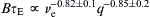 [59] (see Fig. 12.5).
 is exceeded on MAST even for discharges where transport analysis shows no sign of a transport barrier. Measurements of the ion scale density fluctuations using beam emission spectroscopy (BES) [64] in L-mode show that the turbulence is critically balanced [53,65], that is, exhibiting comparable time scales for drift-wave drive, parallel streaming, magnetic drift and de-correlation of the fluctuations. In the gradient region (0.4 < r/a < 0.8) the turbulence de-correlation times, τc are found to be always shorter or comparable to 1/γE, with γE the perpendicular E × B shearing rate. Assuming a Boltzmann response of the density fluctuation δn/n ≈ eϕ/Te (ϕ, plasma potential), the BES measurements also allow an estimate for the time scale associated with the advection of the fluctuations,
  , excluding zonal flows [65]. A correlation of
 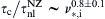 is found, hinting at the presence of ion scale zonal flows as a possible mechanism regulating the turbulence on MAST [65]. Measurements of velocity fluctuations are currently not able to confirm directly the zonal flows but are consistent with their presence [66]. BES data have also been used for direct validation of global gyrokinetics of turbulent transport in MAST [67] (eg, using the particle in cell code NEMORB).
 might still be limited by so-called subcritical turbulence. This turbulence is excited above a critical
  predicted to conform to a surface in (γE, q/ε) referred to as zero-turbulence manifold [68] (ε = a/R = A−1: inverse aspect ratio). On MAST the observed scaling of
  with the neutral density in the tank is found. The wide range of variation suggests a genuine change in particle behaviour with increasing tank gas density. This is also observed in estimates of the energy confinement time at high density. Good particle control with a large tank volume can only be achieved with a baffled divertor chamber and fuelling from the divertor, the HFS or with pellets [71] as foreseen in MAST-U (see Section 12.3). The walls on MAST act as particle sinks throughout the discharge if conditioned by 4He glow discharge cleaning or boronisation, and in most discharges more than 80% of the inventory is retained in the walls [73].
 , well above this limit [74] (see Fig. 12.6), both with fuelling by gas or pellet. In high-current H-modes
  was reached for 20 ms, but only with pellet injection. Deep pellet injection can increase the fuelling efficiency dramatically, and up to 75% efficiency has been estimated for Ohmic discharges without H-mode. With NBI the fuelling efficiency decreases.

 (see Fig. 12.8). This data supports the model that collisionality-dependent neoclassical corrections to the ion distribution function alter the turbulent momentum transport [82]. ITER and DEMO rely on the mechanisms of intrinsic rotation to build up a strong enough rotation to suppress certain stabilities, and the validation of basic theory is of particular importance.
 type-III ELMs exist. At lower collisionality
  these transit into type-I ELMs, whilst also a low-density branch of the type-III ELMs exists
  , initially called type-IV ELMs sitting on the same isobar in
  and
and  as the high-density type-III ELMs. Due to the high-heat loads connected with type-I ELMs (Section 12.2.4) the smaller natural type-II ELMs with good confinement may be the more attractive regime for a fusion power plant, but this regime may not extrapolate to ITER, DEMO or future STs at lower collisionality. Type-III and type-IV ELMs also have acceptable heat load, but due to the lower pedestal pressure give lower confinement.

 for the lowest collisionality
  with pedestal temperatures in excess of
  [94]. During the ELM crash there is evidence from electron cyclotron emission that transient parallel electric fields generate highly superthermal electrons [102].

 [58,92]. This is consistent with kinetic ballooning modes (KBM) clamping the pedestal gradient such that the width increases until the stability boundary is encountered [106]. Indeed the pedestal pressure and its gradient, eroded by the ELM crash, quickly recovers in a narrow part of the pedestal region and then the pedestal top pressure grows due to the widening of the transport barrier until the profiles become unstable (see Fig. 12.13). The pedestal width at low collisionality is much wider than at high collisionality. Distinguishing in the data set for the pedestal width between low and high collisionality shows that different effects could be important at the different collisionalities [94].

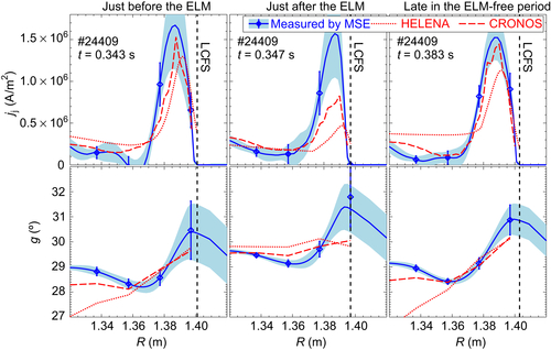
 measuring the ‘damage’ to the target (ITER limit ηELM < 40 MJ/m2 s1/2) has been reduced by a factor of 8. As can be seen from Fig. 12.12, as a function of ELM energy loss the peak heat flux of (red) mitigated ELMs behaves similar to (black) unmitigated ELMs.
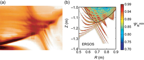
 , evolution has first a quick recovery phase followed by a longer phase where
  . Secondly, the presence of fast ions can also stabilise MHD modes such as, for example, sawtooth oscillations (see Section 12.2.5.1). To allow steady-state operation in a tokamak the plasma current has to be maintained most likely by auxiliary current drive often provided by accelerated ions. Current drive is even more important for future STs, since neutron shielding of high-field side coils is difficult at A ≈ 1.5–2 allowing only for, if at all, a sacrificial solenoid. In particular, the UK version of the CTF is expected to have strong auxiliary current drive by NBI (NBCD) also providing a large fraction of the neutron flux. Finally, the instabilities can react on the fast-ion distribution function leading to transport in radius and velocity space, thereby affecting both heating and current drive or even loss of the fast ions. In the latter case high-heat loads on the first wall could be encountered, which may prove challenging. The complexity of the problem requires an integrated approach strongly supported by modelling both the instabilities and the transport.
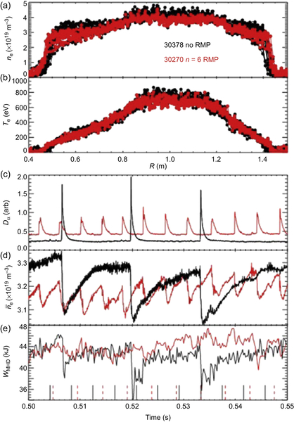

 supporting a model for explosive TAEs [118,124] driven by a spontaneous hole-clump pair in the fast-ion distribution. Also chirping reversed shear Alfvén eigenmodes (RSAE) indicative of a nonmonotonic q-profile have been observed in discharges with a fast plasma current ramp-up (dIp/dt ≈ 5 MA/s) or a double current ramp [26,119]. In addition to this rather low frequency f < 200 kHz activity, compressional AEs (CAE) have been observed in two bands between 0.4 MHz < fCAE < 2.5 MHz [120]. In mixed H and D plasmas apart from CAEs also fast particle driven ion-ion hybrid waves with frequencies up to 2.25 times the central deuterium ion cyclotron frequency
  have been observed [125]. The wave spectra of such plasmas in the ion cyclotron range should be similar to those of DT plasmas in tokamak reactors. With increasing H concentration, the waves in the D ion cyclotron range are suppressed. Analysis of the cut-offs and resonances for these waves using the cold plasma dispersion relation can explain the observed mode activity.

 . As already discussed in Section 12.2.2, the transient heat loads during ELMs have to be mitigated, but also the continuous heat load in between ELMs or in L-mode can become too high. MAST operates in a divertor configuration (see Fig. 12.2), where a poloidal field null is used to create a thin scrape-off layer (SOL) to separate the plasma wall interaction from the plasma core. The width of the SOL is determined by the interplay between the slow turbulent cross-field transport and the fast parallel transport. Current estimates for future devices predict that the exhaust heat is funnelled through a layer of a few mm thickness [137] at the midplane, since the SOL width is roughly proportional to 1/Ip. Angling of the target plates as well as expanding the poloidal flux helps to spread this layer over a wider so-called wetted area. In an ST with a conventional divertor, the radius, RSP, where the separatrix strikes the target plate – the strike point – is much smaller than in a conventional tokamak. This is in particular true for the inner target, even though the ST will most likely be operated in double null (DN) configuration. This reduces the heat load arriving at the inner target and DN is now also explored as an option for DEMO despite the loss of plasma volume for a given magnetic field volume. The small RSP means that the wetted area is smaller, alleviating the heat exhaust challenge for future STs. Advanced divertor concepts as foreseen for the upgrade to MAST (see Section 12.3.2) will help to meet the challenge.
 . Also in L-mode profiles are represented by the Eich function [142]. Both in H- and L-mode different values for S are found in SN and DN, showing that S is not only dependent on the magnetic geometry but also the transport regime. To predict S for future devices, instabilities in the divertor causing cross-field transport may be important (see Section 12.2.4).
 recombination becomes important and a neutral cushion forms between the plasma and the target – the target detaches over a part or the full heat flux profile. At least a partially detached target is needed to tackle the high nontransient heat loads in future devices. Despite the open structure of the MAST divertor, onset of detachment at the inner strike point in the rib divertor was observed for L-mode, H-mode and Ohmic regimes. In L-mode also the onset of detachment on the outer target could be observed, but only at low power and with a much lesser degree of detachment. During ELMs the strike points attach. In L-mode the inner strike point starts to detach at line-averaged densities above
  [144,145], where nG is the empirical Greenwald density. With powers flowing over the separatrix Ploss < 1 MW full detachment is observed with
  . With the new divertor partial detachment in L-mode was obtained at PNBI = 1.1 MW only with HFS gas fuelling close to the inner strike point [146].
 , which is typically a factor of 10 larger in an ST compared to conventional tokamaks, due to the low aspect ratio. This term leads to changes in the charged particle velocity distributions near regions with large
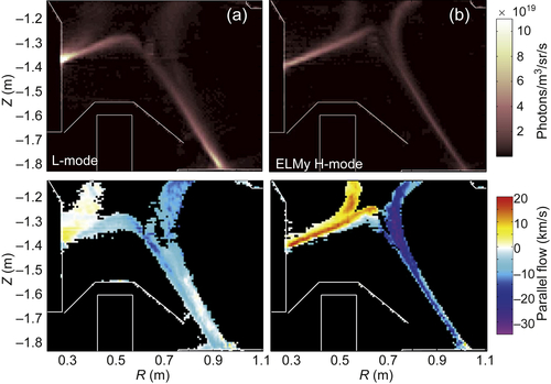
 is smaller than the typical filament size at the midplane of Lrad = 3–5 cm and Lθ = 9–12 cm inter-ELM and Lrad = 5–10 cm and Lθ = 7–9 cm in L-mode. The measured heat carried by the filaments is only a fraction of the heat arriving at the target [158], but the filamentary cross-field transport dominates the far SOL. This is also confirmed by measurements of the ion and electron temperatures in the filaments [159]. Whilst this is good news for the heat loads on the first wall, in future devices it also means that larger cross-field transport may not help with the heat load at the target.
 from an initial low current merging compression start-up, large sawtooth were often suppressed in DN plasmas almost for the entire discharge, leading to a giant crash toward the end of the discharge. The stability of the sawtooth crash is affected by two major factors, the fast toroidal rotation and the deposition of fast ions with respect to the q = 1 surface [164].
 neoclassical effects connected to the field curvature can lead to a growth and saturation of the island – the NTM. For the NTM to form, a seed island is needed that can be generated by other MHD such as sawteeth, fishbone modes, large ELMs or error fields.
 somewhat lower than expected from scalings in conventional tokamaks [31,172]. In addition, the toroidal peaking factors TPF < 4 measuring the asymmetry of the halo currents are similar to the ones observed in conventional tokamaks in all cases fhalo × TPF = 0.19 ± 0.14 is well below the ITER design value of 0.75. More importantly, the ability to change the resistance in the divertor structures showed that the disruption acts more like a voltage source rather than a current source this allows control over the preferred halo current path for future designs [139,172].
 have been achieved routinely. Ion temperatures of Ti ≈ 1.2 keV in about 10 ms are achieved as the reconnection outflow during the merging phase thermalises through the fast shock and ion viscosity in the two downstream areas [180,181]. This temperature scales with the reconnecting poloidal field
  and is about three times higher than measured for plasma formation using direct induction despite a factor of two smaller plasma current. Electron temperatures after the merging are of the order of Te = 0.2 keV and centrally peaked. Clearly in-vessel coils are not feasible for future nuclear devices. Forming the plasma in two separate quadrupole nulls created above and below the midplane can achieve similar plasma currents. In this double-null merging schema the coils can be outside the vacuum vessel and experiments on MAST have achieved Ip = 370 kA with core temperatures and densities of Te = 0.4–0.6 KeV and ne(1.5–9) × 1019, respectively [61].
 are launched from the LFS, converted to elliptically polarised X-mode (E⊥B) at the centre column and then converted to EBW at the upper hybrid resonance (see Fig. 12.26(a)). Here, it is important to launch the waves from below the midplane and to maintain a density below the cut-off for O-mode. Clear evidence for closed flux surfaces and EBW current drive are found (Fig. 12.26(b)). The driven plasma current increases linearly with the launched power (see Fig. 12.26(c)) and injection time
  [187]. With a PECRH = 60 kW RF pulse of
  a record plasma current of Ip = 73 kA was achieved by carefully shaping the vertical field, giving a current drive efficiency of 1.2 A/W, which so far has only been achieved with lower hybrid current drive. More typical current drive efficiencies with less-optimised vertical fields are of the order of 0.5 A/W as shown in Fig. 12.26(c).