Chapter 6. Transmitter
What Is a Transmitter?
So far we’ve talked about a lot of different components of your aircraft but haven’t talked about how the aircraft is controlled. That is where the transmitter comes in (see Figure 6-1). The transmitter is the remote control for your aircraft. You can use the transmitter to send commands to your aircraft by manipulating any of its sticks, sliders, buttons, or switches. The commands are sent from the transmitter to a receiver on the aircraft, which sends those commands to the autopilot or other components.

Figure 6-1. The popular Taranis transmitter, made by FrSky.
Most Common Frequency Bands
In the early days of RC aircraft, modelers operated in the lower range of the AM frequency band. This works great for long distances but has one major drawback: only one person could be tuned to that frequency at a time. If your friend had the same channel set up on his transmitter, he could interfere with your aircraft just by turning his on.
Modern-day transmitters have overcome this problem by moving to the higher 2.4 GHz frequency band and employing frequency hopping to ensure that no one is ever on the same frequency at the exact same time. Even more recently, some manufacturers have begun to move their RC control channels up to the 5.8 GHz frequency band. This is done so that they can reserve the 2.4 GHz frequency band for video transmission (which we will discuss in greater detail in Chapter 8). It is important to know exactly which frequency bands you are operating on, because flying in groups where conflicting frequencies are duking it out for airspace can cause trouble.
A Good Rule of Thumb
Try not to use 5.8 GHz control transmitters with 5.8 GHz analog video transmitters. By the same token, you should keep 2.4 GHz control transmitters away from 2.4 GHz analog video transmitters. These components can cause interference if they are on the same frequency. Instead, use 5.8GHz controllers with 2.4GHz video transmitters, or vice versa.
Different Modes Around the World
One important thing to know when buying an RC transmitter is what mode it operates on. Mode 2 is used in the United States. This places the throttle and rudder on the left stick, with the pitch and roll on the right stick. Mode 1 is used throughout Europe and Japan and reverses the two sticks so that the throttle is on the right.
PWM Versus PPM
If you have shopped around for RC transmitters before, you have likely seen the terms PWM and PPM associated with them. They stand for pulse-width modulation (PWM) and pulse-position modulation (PPM), respectively. These labels identify different communication protocols between your receiver (see Figure 6-2) and the components on your aircraft. The main technical difference between the two is that PPM is digital while PWM is analog. As a builder, you will notice that the biggest install difference between these two is that PPM communicates up to nine channels of control across one wire (digital serial communication), while PWM requires a single wire for each individual channel (analog communication). It is important to consult the documentation for both your receiver and autopilot to know which protocol you should use. If PPM is available, we highly suggest that you use it, because it will clean up your install dramatically with fewer wires. However, not all hardware supports the PPM protocol, so consult your owner’s manual for further reference. At the time of writing this book, APM does not support digital communications protocols on its main firmware fork. As far as we can tell, some developers have been able to create custom firmware that supports it, but we do not advise you to install untested firmware from indie developers as a newcomer to this hobby. Stick with the official releases for now, and you will be much happier in the short term!
Digital by Any Other Name
Many manufacturers have developed their own proprietary versions of digital serial communications and give them their own names. For example, Futaba calls its version SBus.

Figure 6-2. Six-channel receiver by Spektrum.
Step-by-Step Build Instructions
For this portion of the build, you will need:
- One inch of foam double sided tape
- Scissors
- Male-to-male servo leads
Step 1: Identify What You Need
The high-level idea behind installing the RC receiver is easy. You physically mount the receiver on the frame, then plug a series of cables in between the receiver and the autopilot. Because of the differences between PWM and PPM, as well as different manufacturer standards, there are dozens of different connection scenarios between your receiver and autopilot; however, we will only be covering one here. That example will be a PWM connection to a Spektrum style receiver (see Figure 6-3). If you are building something different, consult the owner’s manual of both your autopilot and transmitter for the correct connection sequence.

Figure 6-3. Our Spektrum receiver is plugged into the APM input on the bench.
Which Way Is Front?
Be sure that you are mounting these components in the correct spot. You can easily identify the front of the frame, because it has a large cut out for the vibration isolation mount that the camera will sit on. Another good reminder is that the booms fold back on the frame, not forward.
Step 2: Mount the Receiver
Use a piece of the thick foam double-sided tape to mount the receiver somewhere on your airframe (see Figure 6-4). We recommend placing it inside the front of the frame, as this will give you easier access to the input ports of the APM later in the build.
Keep a Clear Line of Communication
If you are building a kit other than the Little Dipper, try to find a location for your receiver that is close to your autopilot and makes it easy to maintain a clear line of sight with your controller on the ground. Remember that some materials such as carbon fiber can block radio transmissions. It’s a good idea to keep as little airframe as possible between the receiver and the controller on the ground. If your receiver has long antenna wires, run them out of the frame and as low as possible to provide the best possible reception.

Figure 6-4. Spektrum Receiver installed in the nose of the airframe.
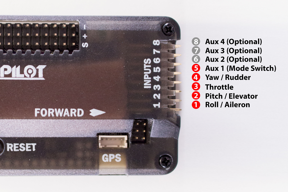
Step 3: Plug in the Receiver
Take five short male-to-male servo wires and plug them in according to Figure 6-5. Connect input 1 to your receiver’s roll channel, input 2 to the pitch channel, input 3 to the throttle channel, input 4 to the yaw channel, and finally input 5 to Aux 1. We will use this channel to switch among our different flight modes.