
Chapter 3. Power Train
The power train is the group of components that generate power and transfer it in a fashion that creates movement. In your car, the engine creates power that is transferred to the transmission that sends it through the axle system and finally to the wheels which make the car move. Our quadcopter also has a power train system that helps us to create movement. Let’s have a look at those components now.
Propellers
The best place to start is at the end, at the propeller. The prop, as it is usually called, is often compared to the tire in automobile power trains; just as the tire “grips the road” to create movement for the car, the propeller “grips” the air, moving the drone. And like tires for your car, props come in all shapes and sizes, and should be selected according to the rest of the power train that will drive them. There are three main specs you want to look for when selecting props: direction, size, and pitch.
Direction
Look carefully at the props in your kit. Notice that the propellers come in two different shapes with opposite angles of pitch. These props are meant to be spun in reverse directions from each other. Each type has the official name of pusher or tractor. Pusher props, sometimes called left-handed props, generate lift when spun in a counterclockwise direction. Tractor props, sometimes called right-handed, generate lift when spun in a clockwise direction. Together, these two props work to keep the aircraft balanced and level. We will discuss how this works in greater detail later in the book.
Size and Pitch
Propellers have a hub in the center that mounts directly to the motor, and two (sometimes more) blades that extend out from the hub. The size is pretty simple to define: it’s measured in inches from tip to tip on a two-blade prop. For the Little Dipper, props in the 5- to 6-inch range are ideal, but some drones can use props up to 29 inches or more!
Pitch is a little more complicated to explain. Most people wrongly assume that it is a measurement of degrees that the prop is pointed up from a flat plane. In reality, the pitch is a measurement of how far the propeller would move forward if it were passing through a solid matter with one revolution. Think of the threads on a wood screw. A fine thread will move a shorter distance with one revolution compared to a coarse thread. Props work in the exact same way. A higher-pitched prop on the front of a plane, or even the back of a boat (in theory) would propel the craft further with one revolution than a lower-pitched prop. It’s also harder to turn, just like that coarse screw!
It is outside of the scope of this book to discuss this in much more detail, but we will mention that the pitch of a propeller is rarely met in real life (see Figure 3-1). Something called prop slip always creates a difference between the distance the vehicle should have moved and how far it actually moved. If you are interested in that, a ton of websites have a wealth of knowledge on the topic.

Figure 3-1. Slip is the difference between the Geometric Pitch and the Effective Pitch.
The higher the pitch, the more air will pass through the propeller with each revolution. Passing more air through the prop results in a higher level of thrust. This is great if you need more lift on your aircraft, but be warned that this results in less efficiency, because the aircraft’s motors need more energy (in the form of battery power) to spin a higher-pitched prop. Moving up to a higher-pitched prop can reduce your overall flight time, as a result of gaining more lift.
Propellers come in all types of size and pitch combinations, each with their own pros and cons. Some are more efficient, while others generate more lift. Typically, the higher the pitch and/or the larger the prop, the more lift that is generated. If you have a heavy aircraft, or one that needs to fly at high speeds, a high-pitch or large prop would be ideal. However, if your needs are for a longer flight time with a lighter payload, something with a lower pitch will probably be best for you. Increased lift does come at a price, though: the efficiency of the prop.
The size and pitch specification is typically something like 0845P or 08X4.5P on the side of the prop itself, near the hub (see Figure 3-2). The first two numbers are the size, 8 (inches), followed by the pitch, 4.5°. The P shows that it is a pusher propeller. Some companies call pusher props left-handed props and may mark them with an L or R (for reverse) in the prop name instead of the P. Tractor props have no letter at the end; their designation would simply be 0845.
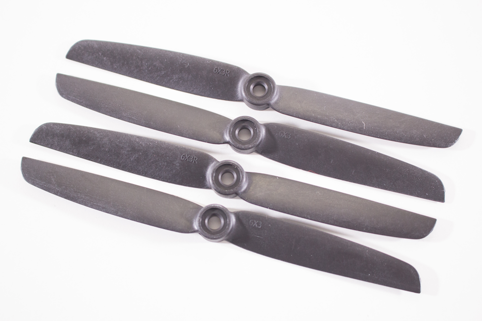
Figure 3-2. Two pushers and two tractors.
Balancing Props
Here we find ourselves drawing another parallel between tires and propellers. Just as your tires need to be balanced to spin smoothly at high speeds, so too do your props. This is a delicate procedure, but one that is critical for anyone in this hobby to master. When you balance your props, you are making sure that each blade of the prop has an identical weight and will reduce the amount of vibration as it spins at high revolutions per minute (RPM).
The process is quite simple in theory: mount the prop you need balanced to a free-spinning axle. This free-spinning axle can be achieved in a number of different ways. Place a metal rod through the middle of your prop mounting hole and suspend that between two magnets, allowing it to spin from an almost frictionless fulcrum point. This lack of friction allows any heavy spot on the propeller to gently rotate toward the ground, under the effects of gravity.
Is the propeller perfectly motionless, or does it want to “lean” in one direction or the other? Using this technique to identify heavy spots in the prop, one can either apply additional weight to the light side, or subtract weight from the heavy side. Keep in mind that these are typically very small adjustments. Adding weight might come in the form of a few small clips of Scotch tape or label stickers, while subtracting weight is usually done with sandpaper and a bit of patience. When fully balanced, the propeller should be able to be moved to any position without one blade or the other leaning toward the ground.
If the thought of building a prop balancer sounds intimidating, don’t worry. Several companies make balancers of all shapes and sizes. The model that we use, shown in Figure 3-3, is one that we have had as long as we have been working with RC aircraft.
Modern-day propellers come pretty close to perfectly balanced from the factory, but it’s always a good idea to double-check them yourself. Usually the better quality the prop is, the more likely it is to come balanced from the factory. Cheaper props may save you a little money, but you will have to spend the time to balance them yourself.
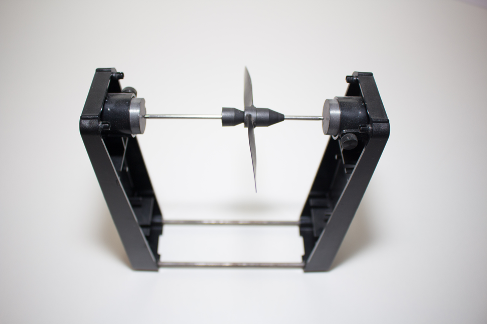
Figure 3-3. When perfectly balanced, the prop should be able to sit in the balancer in any position without falling in one direction or the other.
Motors
One major difference between our quadcopter’s power train and your car’s is that we use a direct-drive system rather than a transmission. With your car, you have one main source of power: the engine, which is connected to the transmission, which divides that power among the wheels that need it. With direct drive, each wheel, or prop in this case, is directly attached to its own power source. For our quads, the power source is a brushless motor.
Sizes
Most modern brushless motors in the hobby industry are identified by the width and height of the motor housing (see Figure 3-4). A 2216 motor is 22-mm wide and 16-mm tall. Of course, not every company subscribes to the exact same naming conventions, so it’s always a good idea to refer to a spec sheet when possible.
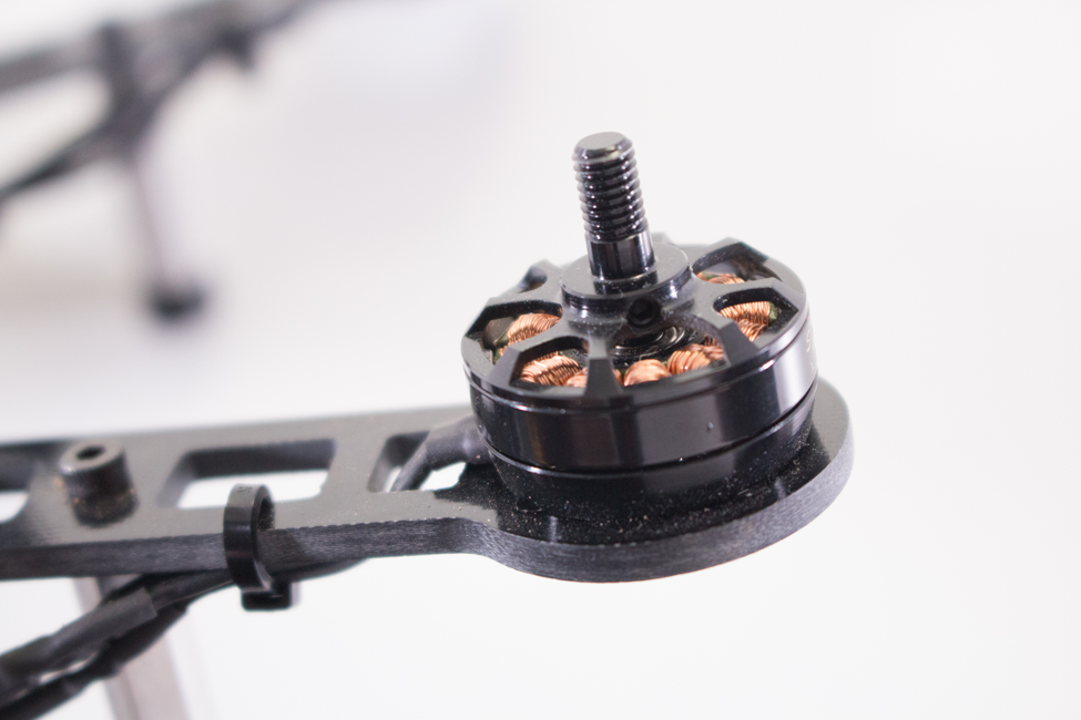
Figure 3-4. These 2204 motors are rated at 2300 kV and work with 5- or 6-inch props.
kV Rating
Another spec that you have probably seen stamped on the side of brushless motors is the kV rating. This tells us the RPM of the motor for each volt of electricity fed into it. This measurement is under zero load on the motor, so actually RPM would vary depending on friction and load. You can now see how this rating is a sliding scale for RPM depending on the battery voltage. A higher voltage battery will make the motor spin faster, but the kV rating is still the same.
Pairing with the Right Props
Each motor will perform at different levels depending on the propeller it is paired with. These days, the guesswork is usually minimal, because most of the motor manufacturers post the recommended prop specs for their motors. To determine the correct prop for your build, you should have an idea of what your drone’s total weight will be once you are done. The heavier you plan your build to be, the larger prop you should use based on the manufacturer’s suggestions.
Total Lift
A common term you will hear in relation to motor and prop combos is their total lift, which is the amount of upward thrust a motor/prop combo generates in the real world. This is typically documented with a weight value that represents the lift generated at 100% throttle command. (Most manufacturers provide this information.) The 2204 motors we used on the Little Dipper build can generate a total lift of 539 grams with a 6 × 3 prop. If we changed props, the lift number would change. Obviously, this is measured for each motor and propeller. To calculate the lift of the entire copter, multiple your results by the numbers of arms on your copter (four for our quad). For the Little Dipper, that works out to be (4 × 539 grams) 2156 grams of lift!
Electronic Speed Controllers
Electronic speed controllers (ESCs) are small electronic circuits that are used to independently control the speed and direction of each motor on our quad. Four ESCs are installed on our aircraft, each designed specifically for use with brushless motors. They work by converting power from the main flight battery into a sequence of electrical signals that are sent across three different wires to the brushless motor. That sequence controls the speed, rotation, and even braking ability of the motor. The required speed for each motor is communicated to each ESC from the flight controller. We will have more on that in the next section.
Classification: Amps and volts
There are generally two main specs you need to look for when buying ESCs: amperage and voltage. The number of volts an ESC is rated for determines what size battery you can use with the ESC (we will discuss batteries in more depth in “Flight Battery”). For now, we will just point out that the unit we will be using in our example is a three-cell battery rated at 12.6 volts. Remember the motor spec sheets we mentioned while discussing total lift? Those same specs generally contain the current draw in amps as well. That information is what you use to determine what size ESCs you need for your desired motor and props.
SimonK firmware
The types of ESCs used in hobby-grade drones were originally designed to be used in RC airplanes. In an effort to upgrade performance, RC enthusiast Simon Kirby developed an open source firmware for hobby-grade ESCs, appropriately called the SimonK firmware. His upgrade provided a faster response time for the motors, which greatly improved the aircraft’s stability. Most major ESC manufacturers now offer SimonK ESCs specifically tuned for multirotor use (see Figure 3-5).
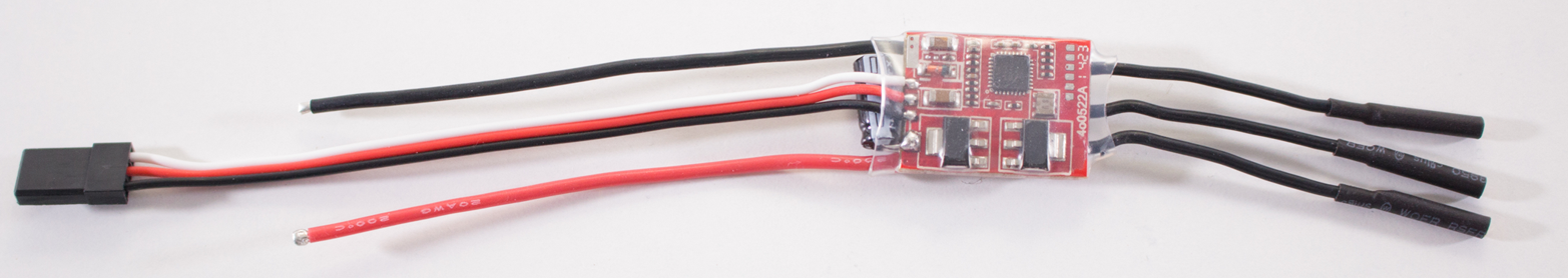
Figure 3-5. The ESCs we use in our example build are rated for 12 amps and up to 16.8 volts (4S battery).
Flight Battery
One of the most important technological developments that helped give rise to the current civilian drone is the lithium-polymer (Li-Po) battery. Very similar to those used in smartphones, Li-Po batteries have a much greater capacity-to-weight ratio than older-generation nickel-cadmium (NiCD) and nickel-metal hydride (NiMH) batteries. That weight savings was key to helping UAVs get off the ground.
Capacity and voltage
Most modern Li-Po batteries are classified according to their capacity and voltage. All Li-Po batteries achieve their end voltage by wiring up a series of smaller battery cells inside the main battery unit. Each cell is rated for 3.7 volts (4.2 fully charged). That means a three-cell battery, such as the one in our demo, is rated for 11.1 volts (3 x 3.7v) and can reach 12.6 volts (3 x 4.2v) when it is fully charged.
The unit of measurement for capacity is the amp-hour (Ah). This describes how long the battery charge will last under certain loads: a 10 Ah battery powering a 1-amp device should last around 10 hours. The same battery with a 5-amp load will last around 2 hours. All of our batteries will come with a milli-amp hour (mAh) rating that determines the capacity of our battery (see Figure 3-6). A battery rated at 2200 mAh has a higher capacity than one with only 1500 mAh. In theory, this battery will last more than 30% longer than the 1500 mAh. In the real world of aviation, though, that might not be the case. A 2200-mAh battery weighs more than a 1500-mAh battery, which means it will have to expend more power to lift its quadcopter. We will discuss this delicate balance more throughout the book.
Although Li-Po batteries helped propel our hobby forward, they still had some drawbacks. Li-Po batteries become unstable under certain circumstances and can catch fire!
For this reason, you should always use great care when handling Li-Pos. Replace damaged batteries, and never use a battery that has been punctured in any way; that is a recipe for disaster! Use fireproof bags when charging Li-Po batteries. Simply hook your battery up to the charger as you normally would, then place the battery inside of the fireproof bag and close the opening around it as much as possible. It is always a good idea to keep an eye on your batteries while charging.

Figure 3-6. Three-cell 2200-mAh main flight battery.
Leave a little in the tank
The rule of thumb is to never discharge your battery below 3.2 volts per cell. That means that for a three-cell battery, discharging below 9.6 volts will damage it. We find that setting an alarm for 3.5 or 3.4 volts per cell lets us land with just enough in the tank (about 20%) to keep our batteries happy. Also, avoid storing batteries that have a full charge. Most decent chargers have a storage setting you can use that brings it down to a nice 3.8 volts per cell. This will greatly increase the life of your batteries.
Step-by-Step Build Instructions
For this portion of the build, you will need (see Figure 3-7):
- Soldering iron and solder
- Helping Hands or some other clamping system
- Heat gun
- 12 pairs (male and female) of 2-mm bullet connectors
- Several inches of 1/8-inch heat shrink
- Wire cutters/strippers
- Allen wrenches
- Small zip ties
- Double-sided foam tape
- Scissors

Figure 3-7. The materials list for this chapter is pretty serious!
Step 1: Mount the Power Distribution Board (PDB)
The very first thing we need to do is secure a location in our dirty frame for the PDB. At the time we did our build, we made our own PDB from copper-clad G-10 (see Figures 3-8 and 3-9), but there are many small inexpensive versions on the market that fit the need. This one fits perfectly in the middle of our dirty frame. Start by applying a couple of small strips of double-sided tape to the back side of the PDB (see Figure 3-10).

Figure 3-8. Our DIY power distribution board cut from copper-clad G10.

Figure 3-9. This is what our PDB looked like—we tinned a few solder spots and added liquid tape for a layer of insulation.
Now press the PDB into place in the middle of the dirty frame where it will be easily accessible by the battery lead, ESCs, and any extras that need access to power (see Figure 3-11). There is a 3-mm hole in the middle if you would like to also add a screw for extra support. We found that the double-sided tape did a very good job holding it in place and opted to not use one. If you do use a screw, try using a small nylon screw and nut, which will save on weight and also does not act as a conductor.

Figure 3-10. Applying double-sided tape to the back side of the PDB.

Figure 3-11. The PDB is pressed firmly into place.
Step 2: Solder on the Bullet Connectors
Th is step is somewhat optional, but it can make the install a lot easier. Bullet connectors allow you to plug and unplug the ESCs and motors into each other rather than soldering them directly. The pros to using them include ease of use during maintenance, troubleshooting, and upgrades. The cons include failure due to loss of contact. If a bullet connector fails, it can cause a crash on a quad (one motor out of four stops spinning and you fall like a rock). With this list of pros and cons, you can understand why people have sharp opinions about these connectors in both directions. We will let you decide for yourself if you want to use them, but this book will assume that the user has them installed. If you decide not to use them, we recommend that you directly solder your connections and seal them with heat shrink. Just make sure your connections are right before you fire up that iron!
Pull out the third-hand helper and turn on your soldering iron—it’s time to get to work!
Bullet connectors, like almost every other type of connector on the face of the earth, are made up of a pair of connectors: one female and one male. We will be installing the male ends on our motors and the female versions on the ESCs. This is considered a best practice, as the ESC is the end providing the power and the female bullet will be shielded to provide protection when things are not plugged in.
Begin by taking one of your four motors and stripping away about 1/8 inch of the insulation from each of the three motor leads. Next, tin the wire tips by adding just a bit of solder to the tip of your iron and coating the outside of your motor leads with it (see Figure 3-12).

Figure 3-12. The motor leads are stripped, tinned, and ready to take the male bullet connectors.
Next, we are going to get out our third hand and use it to add the male bullet connectors to our motor leads. Clamp one bullet connector into one of the alligator clips with one of the tinned motor leads in the other. Take your time and make sure that you can position both of these parts in a comfortable way so that you can easily access them with your soldering iron. Once you have everything configured as needed, place your iron on the outside of the bullet connector, allowing it to heat up for just a few seconds before applying some solder to the inside of the connector where the wire sits. Refer to Figure 3-13 for more info.

Figure 3-13. Everything is in position and we are ready to solder our first connector on.
Apply a moderate amount of solder without going overboard. Once the end of the bullet connector appears to be close to full, remove the iron and solder. Allow the connection to cool for a few moments before removing it from the third hand (see Figure 3-14).
Congrats: you just finished your first solder job on this build! Does it feel good? We hope so, because you have a ton more to do. Let’s get to it!
Once the solder has cooled, remove the motor lead and bullet from the third hand and repeat those steps to solder the other two motor leads and bullet connectors. After your first motor is done, repeat the steps for the remaining 3 motors. When you are done, you should have 4 motors with 12 male bullet connectors soldered to all of their motor leads (1 on each lead).

Figure 3-14. Our solder is cooling while being held in place with the third hand.
Now it’s time to insulate our connection. For that step, we will need our 1/8-inch heat-shrink tubing and a heat gun (or hair dryer if you don’t have one). Cut three 1/2-inch sections of heat shrink and loosely fit them over your newly soldered bullet connections. You want to place the heat shrink across the back raised portion of the connector, as the front male plug part will be inserted into the female plug (see Figure 3-15). If we have heat shrink blocking the connection, it can lead to an unreliable plug. Feel free to plug the male and female plugs into each other a few times and take note of where the connections take place. This will help you better understand where you should—and, more important, should not—have heat shrink placed over your connection.

Figure 3-15. Heat shrink is in place and ready for the heat gun.
Once you have the heat shrink in position, get your heat gun ready. We will gently apply some heat to the heat shrink (see Figure 3-16). Try to position the wires so that you can heat one at a time, especially if you are new to this process. If you are using a hair dryer or heat gun with a lot of wind displacement, be careful that the moving air does not move your carefully positioned heat shrink. Apply this process to all three leads and you should end up with something that looks like Figure 3-17. It only takes a few seconds to shrink the tubing. Once it’s tight around the connector and wire you are good to move on.

Figure 3-16. Using our heat gun to shrink our tubing for insulation purposes.

Figure 3-17. The finished product.
We are starting to make some real progress. At this point, you have four motors with bullet connectors firmly soldered onto each of their leads, which are carefully insulated with heat shrink. Now it’s time to do it all over again with the female connectors on the ESCs. Depending on what ESCs you have bought, there may already be bullet connectors soldered on. If yours do have connectors in place already, check that they work with your male motor bullets. If everything seems to connect nice and snug, skip the rest of this step.
As with your motors, find the three black leads coming out of your ESCs (not the servo plug, the raw wires), strip about 1/8 inch of the insulation, and prepare the wire for soldering. We are going to follow the exact same steps that we did for the motors with the only difference being that we are soldering the female connectors on this time (see Figure 3-18). Walk back through the previous steps if they’re not already ingrained in your head from having done it so many times!
After you have all the connectors soldered up and are ready to begin insulating them, take note of the difference in area that needs to be insulated between the male and female plugs. Rather than the 1/2 inch of heat shrink that you used for the male plugs, the females will require an inch or more (see Figure 3-19). The heat shrink should go just to the tip of the connector without going over while still extending over the wire on the other end. Keep in mind that your heat shrink will change shape a little as it shrinks, so it might pull back from the edge when you apply heat. We usually position it to stick past the edge of the connector just a tiny little bit in anticipation of it lining up perfectly after it has shrunk. If you try this technique and it sticks out over the edge after it has shrunk, use a razor blade to carefully cut any parts away that obstruct the male connector from making a solid connection (see Figure 3-20).

Figure 3-18. Soldering up our first female bullet connector.

Figure 3-19. Be sure to cut the heat shrink to the right length for the female connectors.

Figure 3-20. After applying a little heat, everything looks as snug as a bug in a rug!
At this point, we have four motors with male bullet connectors and four ESCs with female bullet connectors. If you haven’t done so already, let’s try plugging them into each other and see how they fit (see Figure 3-21).

Figure 3-21. Success: everything fits like a glove.
Fantastic—you are well on your way to getting your power train installed on your drone. At this point, put down what you are doing and grab your favorite refreshment from the kitchen. You deserve it!
Step 3: Mount the Speed Controllers
Electronic speed controllers are typically mounted in one of two ways: either on the frame itself, or out on the booms near the spinning propellers in order to get additional cooling from the downdraft of the props. Because our booms fold on this particular frame, we will be mounting the speed controllers on the inside of the dirty frame. Use double-sided tape to mount the speed controllers. Apply a small strip about 1/2-inch wide to a single side of the ESC (see Figures 3-22 and 3-23). Check to see if one side is more flat than the other. Sometimes ESCs can have a large round capacitor that sticks up on one side. If you find that to be the case with your ESC, apply the tape to the other side and stick the capacitor up so that the tape can have the most amount of surface coverage as possible.

Figure 3-22. Apply a small strip of double-sided tape of the flattest side of the ESC.

Figure 3-23. Repeat for all four ESCs.
Now that we have the tape applied to the ESCs, let’s position them in our subframe. Take one of the ESCs and make sure the tape is peeled back and ready for mounting. Locate the open space in the dirty frame around where we installed our PDB. Try to mentally separate this into quadrants and place each ESC into its own space. The red and black power leads coming off the ESC should be pointing toward the center of the frame, while the black motor leads we used in the last step point outward. Be sure that you position the ESC high enough so that another can fit underneath it. Refer to Figures 3-24 and 3-25 for more info.

Figure 3-24. Position the ESC and then press it firmly into place, making sure there is enough space below it for another unit.

Figure 3-25. When all of the ESCs are in place, it should look like this.
Step 4: Solder up the Power Supply
The next step is to solder up the power supply. The overall concept here is to connect the positive and negative leads (red and black wires, respectively) from each of the ESCs in a parallel circuit. If you aren’t familiar with a parallel circuit, that’s OK. It’s a pretty simple concept. It simply means that all of the red wires (positive) are joined together in one connection while all of the black wires (ground) are on another connection. If you look at Figure 3-9, it becomes very clear how that works. We have one strip on the board for positive leads and one for ground. All of the ESCs as well as our main battery lead will connect to the PDB.
Let’s start with a single ESC as the first example. Take the red wire coming out of your ESC and determine how long it needs to be in order to effectively reach a positive circuit on the power supply (in our case, the left-hand strip). Now clip that wire to that length (or just a tiny bit longer, just in case) and strip off 1/8 inch of insulation from the tip. Now tin the exposed wire with your soldering iron and get it ready to be attached to the PDB (see Figure 3-26).
Once you have the positive lead tinned, make sure the tip of your soldering iron is nice and clean before loading it up with a little more solder. Next, take your needle-nose pliers and use them to hold your ESC lead onto the PDB at the point where you want to make the connection. Make sure you are on the correct PDB circuit. This is our positive lead, so make sure it’s on the positive circuit. Finally, apply your hot iron to the top of the positive lead, sandwiching it between your iron tip and the PDB. If you have applied enough solder to all the components, they should all melt together with no problem. Once that happens, remove your iron while continuing to hold the lead for a few more seconds with the pliers. If you pay attention to the solder, you will see it cool in a matter of seconds. It will take on more of a matte finish look and less of a liquid appearance. Once this has happened, you can remove the pliers and check the connection. If it appears to be loose at all, repeat the necessary steps until you have a solid solder joint (see Figure 3-27).

Figure 3-26. Tinning our first ESC power lead before attaching it to the PDB.

Figure 3-27. Our first lead is soldered and seems to be a solid connection.
After you have the first positive lead in place, repeat the same steps for your negative lead on the same ESC. The only thing you should do differently is connect the lead to the negative circuit on the PDB (in our case, the right-hand strip); see Figures 3-28 and 3-29.

Figure 3-28. Solder the negative lead in the same fashion, making sure you connect it to the negative circuit seen here on the strip closest to the bottom of the image.
Awesome—your first ESC is connected to the PDB! Now do the rest in the same manner (see Figure 3-30). Take your time and think about where you will position the wires for all of the ESCs. Don’t make the mistake of cutting one of your wires too short in an attempt to save space. It’s better to leave a little extra length at first.

Figure 3-29. Our first ESC is all ready to get power from the PDB.

Figure 3-30. Example of another build from our fleet with all the ESCs connected to the PDB.
We are almost done with our soldering iron. Is it getting hot in your workshop yet? The only thing left to solder is the main battery lead. This is attached in the exact same fashion as the ESC leads. Clip some insulation from the end, tin the wire, hold it in place with the pliers, and apply some heat. Be sure that you are connecting to the right circuits and that your solder joint is nice and solid.
Step 5: Mount Brushless Motors
Brushless motors for small drones such as the Little Dipper are constantly evolving. At the time we started writing this book, there were a handful of models on the market that most people used. Just a few months later, there were dozens, and more are being added all the time. Due to this constantly shifting landscape, we are not going to give specific instructions for one particular model but rather the overarching ideas that apply to all the different models.
The concept behind mounting your motors to the boom is very simple; find the appropriate-length mounting screws that came with your motor (there could be multiple lengths) and feed them through the mounting holes on the round end of the boom and into the threaded holes on the bottom of your motor. Once you have them hand-tight, work each opposite screw turn for turn the same way that you would on a car wheel while changing a flat.
Pay Attention to the Thread Direction!
Notice that your motors have a shaft that holds the prop in place. This shaft is threaded, and a nut of some type (called the prop nut) fits over that thread and puts pressure on the prop. In the early days of small drones, those threads were all standard clockwise threads. Because our motors spin in both clockwise and counterclockwise directions, manufacturers realized that if they created motors with standard and reverse threads, they could use the spinning prop direction to help keep it tight. Make sure that you always have a thread that screws on in the opposite direction from that in which the prop will be spinning.
Clockwise spinning motors should have a reverse-threaded shaft. Counterclockwise motors work best with a standard thread.
One catch: not all manufacturers make their motors this way. Many still only use a standard thread on all of their motors. This will still work fine; just be sure to tighten it well and check it regularly (as you should anyway).
The moral to the story is to always know what type of threads your motor shaft has and be sure you are installing them in the right location. If you need to confirm the direction that your motor will be spinning, do so before attaching it to the frame.
For our Little Dipper build, our motors will spin clockwise on the NE and SW motors while the NW and SE motors spin counterclockwise.
Start your mounting process by laying the motor flat on the top of the boom while lining up the mounting holes in the bottom of the boom with the threaded holes in the bottom of your motor (see Figure 3-31). Make sure that you have a motor with the correct thread direction for the anticipated motor direction. The motor leads should run down the length of the boom. Make sure they do not run in any other direction.

Figure 3-31. Our motor is sitting squarely on the boom ready to be attached.
Now manually feed the first screw through the boom’s motor mounting hole and into the threaded holes on the bottom of the motor. Once the first one is done, feed the opposite screw in and keep going until you have all four in place (see Figure 3-32).
Once you have all of the screws manually fed into place, tighten them turn for turn on opposing screws, similar to lug nuts on a car (see Figure 3-33).
Now that you have the first motor mounted in place, move on to the remaining three. Don’t forget to keep an eye on what direction threads you are installing!

Figure 3-32. Feed the screws in the same way you would a set of lug nuts on a car to ensure an even tightness all the way around.

Figure 3-33. Tighten the screws turn for turn to ensure that they are all even.
No Props for You!
Be sure the propellers are not attached to the motors yet. That will be our very last step after we have confirmed everything is working as expected. This is an important safety step.
Step 6: Connect Brushless Motors
Our brushless motors will connect to the speed controllers via the three black wires that that we attached our bullet connectors to earlier. If you’re new to brushless motors, you may notice something funny at this point: the wires are not labeled. But there’s a reason why. There is no wrong way to connect a brushless motor to a speed controller, only different directions of motor rotation. You can connect those three wires in any possible combination and it would never be “wrong” in the sense that you are going to damage the motor; it will simply spin in one direction or the other.
Our ultimate goal is to make the NE and SW motors spin in a counterclockwise direction. But because our build is not complete yet, just hook them all up the same and we can test them later in the book to find out what changes we need to make. Now it becomes pretty apparent why there is value in using bullet connectors! If you had to do this step with soldering directly between the components, it would become much more difficult!
Step 7: Clean Up
At this point, it’s a great idea to use a couple of cable ties and clean up your wiring job. It’s also helpful to place identifying tabs on the servo leads coming out of the speed controllers before you button everything up. This will make your life much easier when working on subsequent projects later in the book. We usually use a fine-tip marker or paint pen and label the motor number on the ESC lead.
Wrapping Up
At this point, you should have your speed controllers and motors permanently mounted. Make sure everything is firmly mounted with little risk of coming loose. Also check all soldering in your power harness/power distribution board to make sure nothing is loose. The connection between your motors and speed controllers should be temporary at this point. We will return to the motor wiring later in the book when all our components are installed.