
Chapter 2. Airframes
What Is an Airframe?
The airframe is the main body of the aircraft. All other components—propellers, batteries, computer, etc.—are mounted to the airframe. Airframes can vary greatly in size and complexity. Some of the airframes we built when we first got interested in flying were very simple designs sketched on the back of a napkin, and cut from pressboard with a jigsaw. Today, we use computer-aided design (CAD) software to design our frames before cutting them out with a computerized numerical control (CNC) machine. We will touch on many of the popular design types in this chapter, but first let’s take a quick look at how these actually fly.
Thrust Vectoring
One common trait you will see with all of these airframes is that they use both clockwise and counterclockwise propellers. This is the foundation that allows multirotors to move in all directions. Every other motor spins in a different direction from the one directly next to it, allowing each motor to be balanced by its opposite motor. As a result, nearly all UAVs feature an even numbers of propellers (with one exception that we will discuss in the next section). On a quadcopter, for example, the NW and SE motors might spin clockwise while the NE and SW motors spin counter-clockwise (speaking in terms of compass bearings). By configuring the aircraft this way, all we have to do to move the quadcopter in any direction, including yaw, is change the speed of a certain combination of motors. For example, to yaw the aircraft in a clockwise direction, we would increase the speed of the NW and SE motors. The “push” of one motor and the “pull” of the other will turn the aircraft in the direction we want.
Aircraft Designs
Figure 2-1 shows the various frame types we’ll look at in the following sections. Notice the direction that each prop rotates compared to its neighbor.
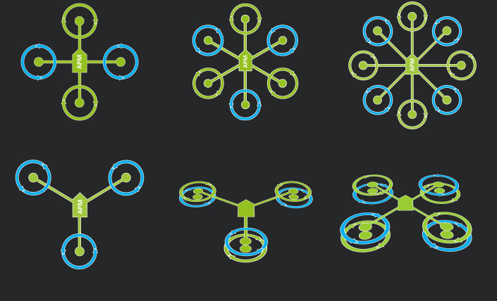
Figure 2-1. Frame types showing the directional rotation of the propellers.
Octocopter
The octocopter design is often used for aircraft that need increased payload along with redundancy. Because it features a total of eight propellers, it is possible for an octocopter to remain in flight if there is any type of failure with any one of the motors or props. The remaining seven will keep the craft in the air without incident. You may also hear this design called a “flat eight.”
Y6
The first of our “coaxial” aircraft, the Y6 features six motors and propellers installed on an airframe with three arms. This is accomplished by stacking motors and props on the top and bottom of each arm with each spinning in the opposite direction from the other. You have probably seen coaxial designs on common store-bought RC helicopters. This design type is inherently more stable but 20%–25% less efficient than a traditional “flat” design.
Materials
Many different types of materials are used to build the modern-day drone. Some of the more popular options include carbon fiber, fiberglass, and various types of plastic or metal. As with most things in this hobby, you’ll always perform a balancing act based on which characteristics are important to you. There is an old saying in this hobby, “Cheap, strong, or lightweight: you can have any two.” While materials like carbon fiber may have a very high weight-to-strength ratio, they can be very expensive to work with. For this reason, many people begin by making their designs from wood, or even 3D-printed acrylonitrile butadiene styrene (ABS) plastic. The frame that we will be working through in this book is called the Little Dipper and is primarily made from G-10 fiberglass (see Figure 2-2). We think this material is a nice balance of weight, strength, and cost.
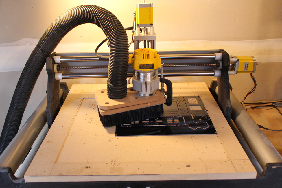
Figure 2-2. G-10 fiberglass frames being cut on a CNC machine.
Keeping It Balanced
No matter what type of frame you are building, it’s always very important to keep the weight balanced front to back and side to side. If you are designing something from scratch, keeping your frame symmetrical is a great way to ensure that it will be easy to balance after your build is complete. If you have to go with a slightly asymmetrical design, try to position your components on the frame in a way that ultimately brings it back into balance.
Note
Your drone’s battery is often a good candidate to reposition in order to bring balance to your design.
Building the Little Dipper Airframe
The Little Dipper is a compact, foldable quadcopter. Its airframe is made up of two subframes that help isolate the motor vibrations from the flight and imaging sensors. These subframes are called the clean and dirty frames. The dirty frame is the bottom subframe, and it holds all of the moving parts such as the motors and the propellers. The clean frame sits on top and holds all of the flight and communication electronics.
Lay out the flat frame parts, and refer to the photographic diagram in Figure 2-3 to identify them. Divide them into the two subframe build portions. Parts A and B make up the dirty frame (A is bottom, B is top), while C identifies the four booms, which will hold our motors and props. Parts D, E, and F make up the clean frame: D identifies the bottom clean frame plate, while E shows the top clean frame plate. Part F is the camera plate, which sits on top of rubber isolation balls (more on that soon).
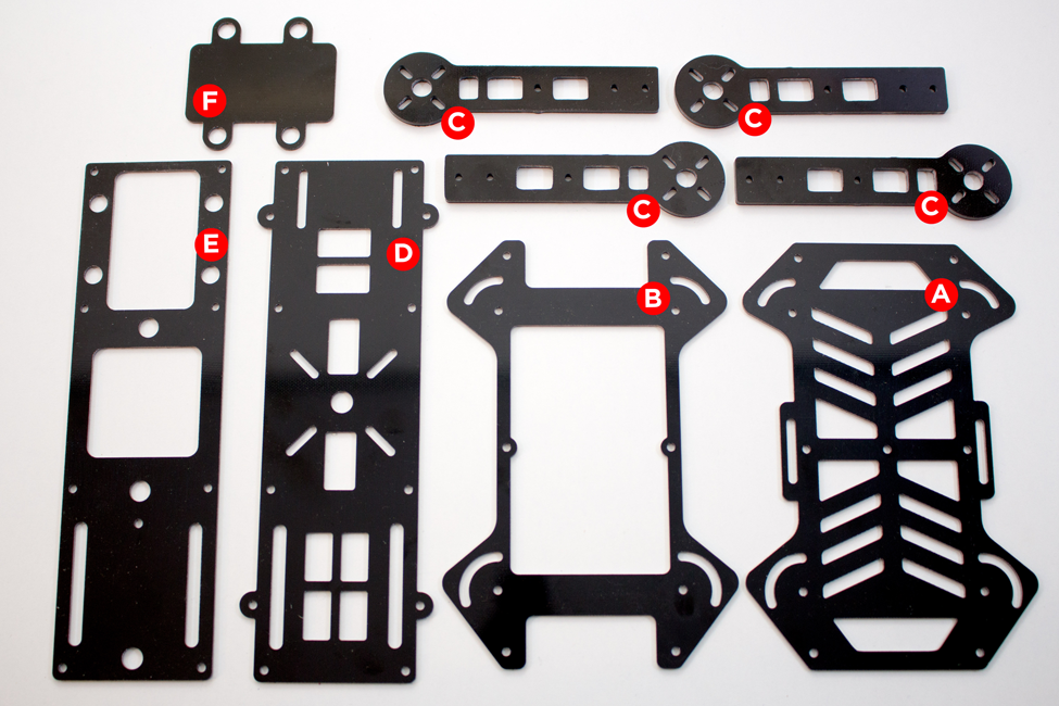
Figure 2-3. You should have all of these parts in your frame kit.
Alternative Frame Options
Although we are walking you through our example build with the Little Dipper, a few alternative options for airframes are presented in Table 2-1.
| Frame Name | Configuration | Independent Booms | Clean/Dirty Frame | Folding Booms |
|---|---|---|---|---|
| Lumenier QAV250 | 250-class quadcopter | No | No | No |
| Blackout Mini Spider Hex | 290-class hexacopter | Yes | No | No |
| DroneKraft Mach 300 | 300-class quadcopter | Yes | Yes | No |
The QAV250 (see Figure 2-4) is one of the most popular frames on the market today. It’s extremely lightweight due to its simple two-plate design and very effective for quadcopter racing.

Figure 2-4. QAV250 with 5X3 carbon fiber props.
Step-by-Step Build Instructions
Here are the tools you will need to get started (see Figure 2-5):
- Metric Allen wrench (2.5 mm). A full set is nice to have, but we will be using the 2.5-mm wrench during this build.
- An adjustable wrench, needle-nose pliers or a 7/32 nut driver. Any of these will work, but if you use the nut driver, make sure it is slim enough to fit into the tight spaces around the frame. A full ratcheting socket will not work, because it is too large. The needle-nose pliers will mark up your hardware slightly, so use those as a last resort.

Figure 2-5. Tools you will need for the frame build.
Step 1: Install the Standoffs
Begin building the bottom portion of the airframe—the dirty frame—by attaching the short aluminum standoffs (see Figure 2-6). Locate the top dirty frame plate (plate B in Figure 2-3). There are four 3-mm holes at each corner of the plate (see Figure 2-7). Use those holes to mount the standoffs with the 5-mm screws (the short black screws included in the kit).

Figure 2-6. Standoffs—either aluminum for stiffness and longer life, or rubber for increased vibration isolation—are used to separate the two subframes.

Figure 2-7. Pointing out the standoff mounting holes on plate B of the dirty frame.
Manually fit the screws through the holes, then attach the standoff on the other side of the plate. The screws should not come out the other side of the standoff (if that happens, you used the wrong screws). When all four are done, plate B should look like an upside-down table with its legs sticking up in the air, as shown in Figure 2-8.

Figure 2-8. All four aluminum standoffs installed on plate B.
DroneKraft Mach300
If you are building out a Mach300, your kit will come with rubber standoffs very similar to those shown in Figure 2-6 and should provide a comfortable level of vibration isolation for your flight controller.
Step 2: Complete the Dirty Frame Assembly
Complete the bottom portion, or dirty frame assembly, by attaching the four booms (plates C in Figure 2-3) and bottom dirty frame plate (plate A) to your top frame plate. When you are finished, it will look like Figure 2-9.

Figure 2-9. The dirty frame fully assembled from plates A, B, and C.
It is best to do this step one boom at a time. Begin by placing plates A and B on top of each other with the standoffs on plate B pointing up. Make sure that both plates are facing the same direction. You can check this by locating the boom holes (shown in Figure 2-10) and making sure that the arched half-moon holes line up between both plates. If they don’t, flip one of the plates (front to back) until the holes match up.
You can identify the boom holes in plates A and B pretty easily. Both front and back mounting holes will have a single 3-mm round hole positioned just above an arched 3-mm slot that allows folding of the frame.

Figure 2-10. Rear boom mounting holes (notice the anchor hole just above the folding slot).
Let’s continue by sandwiching the boom (plate C in Figure 2-3) between the top and bottom dirty frame plates (plates A and B); see Figure 2-11.
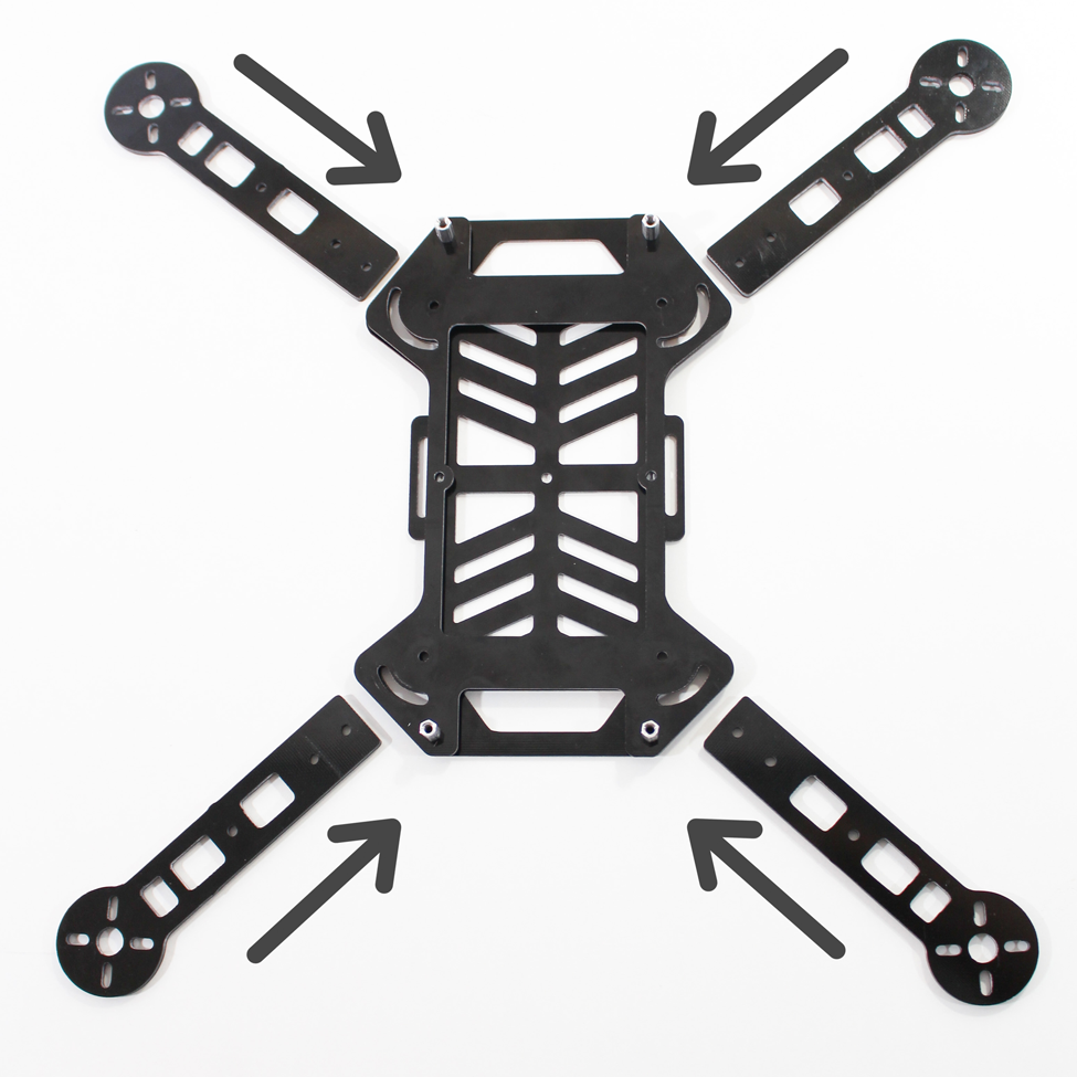
Figure 2-11. The booms are lined up and ready to be sandwiched between the top and bottom dirty frame plates.
Stand Up Straight
The standoffs are added to the design to help isolate vibrations between the clean frame and the dirty frames, so they should be on the top of the dirty frame top plate (plate B).
Now take your first boom and line the two 3-mm holes on the rectangular end with the boom mounting holes. Take a 12-mm mounting screw (the longs screws that came in the kit) and place a flat black washer over it. Now manually push this screw and washer through one of the boom mounting holes in the top plate, then the boom, and finally the bottom plate. We recommend starting with the 3-mm anchor hole first. Once the screw is all the way through the sandwiched set of plates, push another flat black washer on the other side of it before finally placing a 3-mm locking nut on the bottom. Repeat this for the second hole on the boom (see Figures 2-12 and 2-13). Once you have one boom installed, repeat this entire step for the rest of the booms.

Figure 2-12. Pushing the second screw through the mounting holes.

Figure 2-13. Placing the nuts on the bottom of the frame.
Do Not Overtighten the Nuts
You can very easily overtighten the nuts on the boom mounting screws. This will not cause any damage, but it will prevent your booms from folding. You want to tighten them just enough to hold the boom in place firmly, but not so much that it prevents it from folding at all. Practice folding the boom as you are going through this step. The nuts we use, called lock nuts, have a layer of nylon at the end of the thread that holds the nut in place without having to overtighten it. You should still consider checking the tightness of the mounting screws/nuts during regular aircraft inspections.
Step 3: Assemble the Clean Frame
Next, we are going to build out our clean frame. This frame is made up of plates D, E, and F (which we will add later in the book) from Figure 2-3. We will also be using the eight 37-mm standoffs that came in the kit. The overarching idea is to use plates D and E as a top and bottom of our frame that is held together with the standoffs.
Let’s start by finding plate D. You will notice eight 3-mm diameter holes that are positioned around the edges of the plate. These are our standoff mounting holes. Take a 5-mm black screw (one of the short screws that came with the kit) and manually push it through one of the holes (see Figure 2-14). It doesn’t matter which hole you pick, because we will repeat this for all the holes. You also do not need a washer for these screws.
Next, take one of your 37-mm standoffs and thread it on the portion of the screw that is sticking out of the other side of plate D (see Figures 2-15 and 2-16). Once you have it finger-tight, you can tighten it further with your Allen wrench and adjustable wrench or pliers.

Figure 2-14. Pushing the 5-mm screw through the standoff mounting holes on plate D.

Figure 2-15. Threading the first 37-mm standoff on the back of our mounting screw.

Figure 2-16. Our first standoff is installed (the rest are waiting in the wings).
Now we can repeat these steps for the remaining 37-mm standoff (see Figure 2-17). When you are all done, plate D should like Figure 2-18.
Now that we have our 37-mm standoffs installed on plate D, we are ready to attach plate E. If you haven’t done so already, find that plate and take a close look at it. You will notice two important things. First, there are eight identical mounting holes around the perimeter of the frame (just as in plate D) and second, there are two long slots near the edges of the plate on one end (just as in plate D). Place plate E on top of our assembly and make sure the two long slots are directly over of the two long slots on our bottom plate. It should resemble Figure 2-19.
As you may have guessed, we need to thread more 5-mm mounting screws through the holes in plate E into our standoffs (see Figure 2-20). Start by manually placing the screws into the holes and then tighten them with a 2.5-mm Allen wrench (see Figure 2-21).

Figure 2-17. Tightening the final 37-mm standoffs on plate D.

Figure 2-18. Plate D with all the 37-mm standoffs installed and ready for plate E.

Figure 2-19. Plate E on top of our assembly prior to adding the mounting screws.
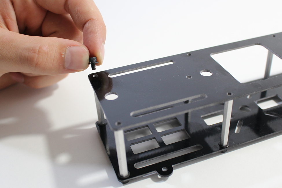
Figure 2-20. Threading our first mounting screw through plate E into our 37-mm standoffs.

Figure 2-21. Once you have all the screws threaded, make sure they are all nice and tight.
Lumenier QAV250
If you went with the QAV250 for your airframe, you will notice that the entire airframe is assembled in a similar fashion to our clean frame. The main difference is that the QAV has booms built into its bottom plate and only uses six standoffs to separate the two frame plates. This will create a lighter frame that is well suited for racing applications.
Good job! You have now built out the basis of both our subframes. If everything went as planned, your build should look like Figure 2-22. It’s finally starting to look like a quadcopter, wouldn’t you say?
Note
Technically speaking, we need to stop our frame build at this point. There are electronics (covered in the next chapter) that need to be installed in both subframes, and that is much easier when they are not attached to each other. That being said, we are going to show you the final step of building out the frame now (it’s a really simple one) and you can refer back to this chapter later in the book when we are ready for it.

Figure 2-22. Both of our subframes assembled and ready to be loaded up with flight components.
Step 4: Attach the Two Subframes Together
Just to reiterate: this final frame-building step should not be performed if you are just getting to the end of Chapter 2. We need to install electronics in both of our subframes, and this step should be saved until we reach the end of Chapter 4 (autopilot install). Because this step is so simple, and for the sake of continuity, we will display it here and you can either refer back to this chapter or (more than likely) pull it from memory.
Begin by placing the clean frame on top of the dirty frame. Line up the four small tabs that stick out from the bottom of the clean frame (with 3-mm holes in the center) with the four short standoffs sticking up from the top of the dirty frame. Make sure that both frames are pointing in the same direction. You can determine this very simply: the back of the clean frame has two long slots along the sides between the back two standoff mounting screws, while the back of the dirty frame is the direction the booms will point when they are folded in.
Once you have placed the frames on top of each other, take your final 5-mm mounting screws and manually place them through the tab holes in the clean frame before tightening them with a 2.5-mm Allen wrench. Repeat this for all four tab holes. Refer to Figure 2-23 to see how it’s done.

Figure 2-23. Attaching our two subframes with a screw through the mounting tab (on the clean frame) into the short standoffs (on the dirty frame).
That’s it—you have attached the two subframes. That was easy, wasn’t it?
Watch It Being Built
You can find a detailed video showing all of these steps as well as the results other readers have had by visiting the companion website.