Chapter 7. Telemetry Radios
Software Monitoring and Control
By now, you may have noticed one very important thing about RC transmitters: they only send communications in one direction, from the transmitter to the aircraft. In order to gain access to any of the onboard data from your aircraft, we have to use a special two-way radio that is known as a telemetry link.
Just as its name implies, the telemetry link takes a series of measurements from your aircraft and sends them back down to the ground where they can be displayed in ground control software (Figure 7-1). In addition, data—such as waypoints, autonomous flight missions, and aircraft configurations—can be communicated up to the aircraft from the same ground control software.
Having access to this type of information while you are still safely on the ground can be a huge advantage. It can help you identify problems before they get out of hand. Some of the data points your ground control software needs are latitude, longitude, altitude, aircraft attitude, current battery voltage, aircraft heading, speed and duration of flight, plus many more. You can find a complete list of all data communicated in your ground control software manual.

Figure 7-1. This Android tablet can be used a ground station with the addition of telemetry radios and a free app.
Step-by-Step Build Instructions
For this portion of the build, you will need:
- One inch of foam double sided tape
- One inch of Velcro
- Zip ties
Step 1: Mount the Ground Station Radio
Your telemetry radio set will actually come with two different radios. One goes on the aircraft while the other connects to your ground control software (Figure 7-2). The ground radio can be mounted in any number of ways; however, we ordinarily use Velcro on the back of the tablet or laptop that runs the software. This allows us to remove the radio when we’re not using the ground control software.

Figure 7-2. Velcro holds the telemetry radio on the back of our tablet while in use and allows for easy removal when we are not flying.
Step 2: Prep the Aircraft Radio for Mounting
For the aircraft radio, we suggest using double-sided foam tape to attach the radio to the frame (Figure 7-3). Cut two small strips about 1/2 inch in width and place them on opposite ends of the radio. As for location, there is some flexibility here, but we recommend you place the radio on the back half of the airframe. This will move the telemetry radio as far away from the RC receiver as possible.
Don’t attach the radio just yet. We want to put the tape in place and have it ready, but we still need to plug the radio in, and this will be much easier to do if it’s not mounted yet.

Figure 7-3. Double-sided foam tape can be used to fasten the radio to the air frame.
Which Way Is Up?
Be sure that you are mounting these components in the correct spot. You can easily identify the front of the frame because it has a large cut out for the vibration isolation mount that the camera will sit on. Another good reminder is that the booms fold back on the frame, not forward.
Step 3: Plug in the Radio
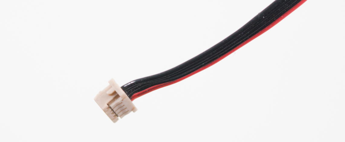
Wiring up your new telemetry radio couldn’t be simpler (see Figure 7-4). Find the correct cable that came with the radio set and plug it into the back half of the aircraft radio. This cable will have five individual wires (four black and one red), but the plug on either end will have slots for six wires, leaving one of them empty. This is normal. The other end of that cable will plug into the telemetry port on your autopilot.

Figure 7-4. Plugging in the telemetry radio will be much easier if done before it’s mounted to the frame.
Step 4: Mount the Aircraft Radio
Now that you have plugged in the radio, go ahead and mount it on the back of the airframe (see Figure 7-5). The double-sided tape should hold it securely in place. Make sure that it sticks out from the frame far enough to allow the antenna to swivel freely as needed, but not so far that it will be in the way as you handle it.

Figure 7-5. The end product with the radio mounted in place.
Note
You will notice small tabs on the sides of the cable plugs that allow the cable to plug in in only one direction. Find those tabs and identify the direction before applying pressure (see Figure 7-6).