
HALLOWEEN HAUNTED HOUSE CONTROLLER
Build a relay board that synchronizes lights, motors, and other electrical devices to a scary soundtrack playing on a computer, and create spooky haunted house special effects! »
Set up: p.89 Make it: p.90 Use it: p.96

Illustration by Erik T. Johnson
GEEK MEETS GHOUL
I loved neighborhood haunted houses as a kid. Trick-or-treating was more of a search for haunted houses than for candy and mischief. I was ever-hopeful that around the next corner, I would find another garage converted into a cardboard-and-bed-sheet maze filled with low-budget frights. But I often thought, “I could do better than that.”
For the last ten years, I’ve been perfecting my technique of scaring kids. This project shows you how to build a tool I frequently use in my haunted creations: a relay board that switches on electrical devices in time to an audio file that’s playing on a laptop. The laptop connects to the controller board via its parallel port. Using this setup, you can then write code that synchronizes lights, motors, fog machines, pumps, laser pointers, and other devices to sound cues in a spooky soundtrack.
SET UP.
Visit makezine.com/03/halloween for source list.

MATERIALS
[A] 120 VAC solid state relays logic-compatible input voltage (range should include 3.3-5 VDC), screw mount, with load voltage and load current ranges sufficient for any AC devices you expect to control. Get one for each device; I used three Crydom D1225 relays.
[B] DC solid state relays single-pull single-throw, logic-compatible input voltage (range should include 3.3-5 VDC), screw mount, with load voltage and load current ranges sufficient for any DC devices you expect to use. I used two Crydom D2D12 relays.
[C] Terminal block for 16- to 22-gauge wire I used a 12-position barrier screw terminal strip.
[D] 25-wire flat ribbon cable
[E] 25-contact male D-subminiature connector with “displacement connection” that crimps onto ribbon cable
[F] 24-pin DIP (dual inline package) plug with displacement connection, for connecting ribbon cable to breadboard. These may be called either “IDC DIP plugs” or “DIP plugs,” but don’t confuse them with plain DIP plugs that don’t bite into ribbon cable.
[G] 470-ohm resistors one for each relay, plus one extra.
[H] LEDs (standard 2V is fine)
[I] Small plugboard (solderless prototyping breadboard)
[J] Four stand-offs or some hard plastic or metal tubing that’s wide enough to accommodate your screws. These need to be long enough or cut to sufficient length to clear height of relays plus some extra headroom for wiring; I used 1.25-inch for relays 0.9 inches tall.
[K] Cable ties
[L] Non-conductive base I used plywood.
[M] Non-conductive transparent cover I used a small sheet of hard acrylic.
[N] Grounded extension cords Get one for each AC relay. One should be at least 6 feet long; the rest can be any length because you’ll be cutting them and only using the ends.
[O] Wire 16-gauge stranded for AC devices, 22-gauge solid core for DC and signals.
TOOLS
Windows-based laptop (or a desktop computer, but those are less convenient and harder to conceal)
Wood screws
MAKE IT.

BUILDING THE CONTROLLER BOARD OF DOOM
Time: A Weekend Complexity: High
START »
1. ASSEMBLE THE CONTROLLER BOARD’S AC SIDE.
My controller board consists of three AC relays (to power 120 VAC props) and two DC relays (to power things like laser pointers and battery-powered props), but you can add another relay. The relays are switched on and off by signals sent from a personal computer through its parallel port. The schematic below shows how the various components are connected. If you can’t read a schematic, don’t worry; you can still build the controller by following along with the photos. (Also, see page 151, Reading and Drawing Schematics.) But to program it later, you’ll need to get into some simple C++ code and do some light tweaking, compiling, and debugging.

Photography by Dale Dougherty
1a. Attach main components to wooden base. Using the photograph as a guide, lay the solid state relays, terminal block, and breadboard onto the base. Mark places for holes, and drill holes appropriately sized for the screws. Using wood screws, attach the components to the base.
1b. Attach receptacles. Cut all of the extension cords approximately 12 inches from their receptacles, and strip ¾ of an inch of insulation at the cut. Mount three receptacles to the edges of the base by drilling through holes and securing with cable ties.

1c. Attach AC power cord. Attach the cut end of the fourth extension cord to the base, and strip ¾ of an inch of insulation.
1d. Attach wires to terminal block. Wire up the AC side of the controller, as shown, using the screw connections on the terminal block. Use short pieces of the #16 wire to connect the hot side of each receptacle to the hot output (Terminal 2) contacts of the solid state relays. It’s always best to switch the hot side, not the neutral.

The wires in extension cords are often color coded: black is hot (live), white is neutral, and green is ground. If yours aren’t color coded, look at the plugs with the blades pointing towards you and the round, ground plug at the top. Hot is the smaller blade, on the right, and neutral is the wider blade. Use a multimeter to test conductivity between the blades and wires to identify which is which.
2. MAKE THE DATA CABLE.
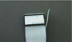
2a. Snap D-sub connector to cable. Position one end of the ribbon cable squarely between the D-subminiature connector’s two rows of forked contacts, and then press down with the strain relief. The connector should snap into a locked position.

Each of the forks (“insulation displacement connectors”) should pierce through the ribbon cable’s insulation and make a connection with a wire inside.
2b. Snap DIP plug connector to cable. Peel one wire away from either edge of the other end of the ribbon cable, and connect the remaining 24-wire ribbon to the DIP plug, using the same method as above.

It doesn’t matter which edge of the ribbon cable you peel the wire away from.
2c. Determine pin-to-pin relationship. Use the multimeter to see which pins on the D-subminiature, parallel port connector correspond to which pins on the DIP plug. The pins we’re interested in are the ones that connect to the parallel port’s Pins 2-9, which are the output data lines, and the port’s Pins 18-25, which are all grounds.
You might sketch a map of the DIP plug’s layout or attach a label to help you remember.
3. WIRE UP THE BOARD’S SIGNAL SIDE.

3a. Wire up the breadboard. Plug the DIP into the breadboard. Using the schematic or photos as a guide, wire up the controller’s signal side, using #22 wire. This will connect the relays’ input terminals to the parallel port via the ribbon cable, while LED/resistor pairs show the state of the parallel port. The first output pin, Pin 2 on the parallel port, will always be on as a general status indicator. Then, starting with Pin 3 and going down the line, each input pin connects to both the positive-side input (Terminal 3) of each relay and the relay’s LED indicator. The other sides of the relay inputs and indicator pairs connect to ground.

4. CONNECT THE COMPUTER.
4a. Secure the DIP connector to the board with a cable tie, so that it won’t get yanked out of the breadboard.

4b. Cover the AC portion of the controller. Mark and drill holes in the base and cover and connect them with the stand-offs. I used clear acrylic so I could still see the LEDs.
4c. Ensure your wiring is correct before attaching to a computer. A parallel port can only source a few milliamps of current, and can be damaged if the data lines are shorted to ground.
4d. Plug the controller into your computer’s parallel port (leave the AC unplugged for now) and see if you can illuminate the LEDs. Use a parallel port monitor such as “lpt.exe” from neil.fraser.name/software/lpt. The port number of the parallel port varies between machines, so be sure to check all options. You may have to change your parallel port’s setting in the BIOS to something other than bidirectional, such as ECP or output only.

Note that a parallel port’s eight output pins are addressed in binary fashion: writing a 0 to the port turns them all off; writing 1 turns on only the first data pin (Pin 2); writing 2 turns on only the second data pin (Pin 3); 3 turns on the first and second, and so on up to 256, which turns on all eight.
4e. Test the controller board by plugging it into 120 VAC and then plugging a lamp into one of its AC plugs. The power to the lamp should now be under computer control.

4f. Attach your devices. AC devices can be attached by simply plugging them in. For DC devices, splice a DC relay’s output terminals between the positive wire that comes from its power supply (for example, the device’s wall wart) and the device’s positive power input. For battery-powered devices, you can use an external battery pack and run the wires through the controller, or use an equivalent wall wart AC to DC transformer and plug that into the AC on the board.

5. CREATE YOUR ACTION SEQUENCES.
The devices you use with the controller complete the display. Lights, strobes, fans, and fog machines are easy; just plug them in. I created one vivid effect by directing laser pointers into the eyes of a stuffed rubber mask, and when the controller switched them on, the eyes seemed to come alive. Projectors shouldn’t be repeatedly power-cycled with a controller, but you can set motors up to block or deflect their beams.
Motors outfitted with rotating cams will pull strings that make skeletons dance and bats flutter, and reels will raise and lower hanging spiders. To drop a guillotine blade, I used a 12 VDC automobile seat motor to rotate a cardboard hook that released the rope. I reinforced this effect with an aquarium pump that gave a quick squirt of warm water just after the blade dropped, treating onlookers to the feeling of fresh-sprayed blood.
5a. Think of some simple but scary scenarios that can be conveyed by sounds and darkness and enhanced by your devices. One approach: weave a story that’s just plausible enough that kids will wonder if it’s true, and while they’re pondering, startle them with something dramatic, like an abrupt lighting change or the hiss of a fog machine.
5b. Create the soundtrack. Using a wave file editor, I sampled, cut, and pasted sounds from Halloween CDs. The sequence of sounds should suggest a series of events, but it needs to be short and concise; trick-or-treaters aren’t known for long attention spans, and you don’t want the next group arriving in the middle and missing the fun. You can hear my guillotine sequence soundtrack at oreilly. com/go/soundtrack.
5c. Download Borland’s free C++ Compiler, then download inpout.dll and add it to your compile libraries. This is what makes calls to your parallel port from Windows NT and XP. For details and links, see hytherion.com/beattidp/comput/pport.htm.
5d. Write the controlling code that syncs your devices to your soundtrack. You can model your code on my sample at oreilly.com/go/syncode. Include inpout32.dll and define all of your devices as variables at the top of the file. Then play your soundtrack file and run through a precisely timed sequence that pushes values to the parallel port (often at machine address 0x0378) and calls to the Sleep function. Compile, run, debug, and repeat as needed.
Or, instead of writing a fixed script, you can also use the controller board to switch lights and other devices in time to the beat of music you’re playing on Winamp. Check out discolitez.com for a Winamp plug-in, or try mine at 8-legs.org/ewilhelm/projects/2.165. My plug-in works by calculating the difference in the Fast Fourier Transform of a song between one time step and the next. When the value of this difference in a narrow frequency range exceeds a threshold, one of the relays is triggered. This lets you set a string of Christmas lights along the floor to flash with the kick drum, sync another at eye level with mid-range beats, and use a third along the roof to complement cymbal crashes.
5e. Dress up your haunted house with other tricks. I discovered that baby Furbys behave very strangely when given half of their normal 6 VDC. Instead of batting its eyelashes and making baby sounds, mine moaned and screamed like it was just skinned alive. So, I completed the effect by actually skinning it and wiring it up to the controller and a 3 VDC source. Remember that in the dark, you often need only to suggest something rather than fully recreate it. For example, two bright white lights and a rush of air from a fan along with the soundtrack were enough to evoke the feeling of a truck stopping just short of trick-or-treaters at the door.
You’ll know you have it right when kids come to the door holding their bags open for treats, watch wide-eyed for a few terror-filled moments, clamp their bags shut and sprint back to their parents before the piece of candy you tried to drop in their bag hits the ground. Happy Halloween!
FINISH X
NOW GO USE IT »
USE IT.

Illustration by Eric T. Johnson
