
RETROVISION 2000 AV CABINET
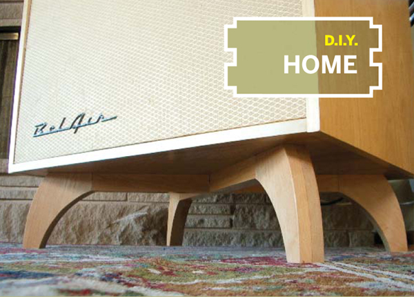
Behind this mid-20th veneer is your 21st century entertainment setup.
Photography by Steve Lodefink
Building a home entertainment center in the form of an Atomic Age TV set.
I really like the 1950’s vintage enameled steel and wood cabinet TVs. At one point, I had a collection of half a dozen classic sets, but they proved a less practical thing to collect than, say, wheat pennies or comic books. Eventually, I jettisoned them all but I could never quite shake my affinity for the mid-century sets.
A lot of people probably consider a brand new Sony 27-inch television a stylish addition to their environment, but for me it was a big ugly plastic assault on my sensibilities. I decided to build a cabinet that looked outwardly like a Populuxe television set, but inside held our entire stack of AV gear. I had been toying for some time with the idea of building a custom housing for a modern television.
This project is very straightforward, but requires some basic cabinetmaking skills and tools. At the very least, you will need a drill, table saw, jigsaw, and a router.
Layout and Design
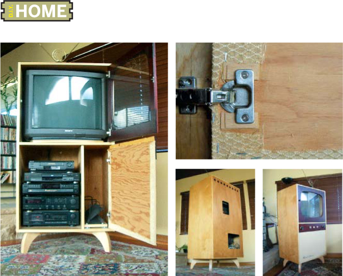
Design your cabinet based on the dimensions of the equipment that it will house. To preserve the illusion that it is an old TV, the cabinet should be as tight fitted to the television set as possible. For best effect, take care to position the television screen directly behind the window of the upper door so that the maximum amount of screen is visible, without revealing the plastic TV case inside. Take into account the height of the lazy Susan, if you use one.
Construct the Cabinet Box
I cut the top, bottom, sides, center shelf, and lower vertical separator from ¾-inch hardwood plywood on the table saw. To provide this large cabinet with adequate rigidity, these pieces need to be assembled and glued up as an interlocking unit.
Use a router with a ¾-inch rabbeting bit to make the edge joints for the top, sides, horizontal shelf, and vertical separator. Cut slots in the side panels to accept the shelf. Similarly, slot the bottom and horizontal shelf pieces to accept the vertical separator.
After gluing this assembly, rabbet the backside of the box to accept a ¼-inch plywood back panel. I nailed and glued the back into place before cutting ventilation holes and strategically placed access ports. Use a hot iron to apply preglued veneer edging to exposed plywood layering.
Build the Base
Fully loaded, this unit is a heavy beast and calls for a sturdy stand. You could use prebuilt furniture legs to save time and effort, but I made a Noguchi-looking base out of maple. If 2-inch-thick maple stock is available, the stand could be made with just two parts. I had some ¾-inch stock on hand, so I built it up out of eight separate components. The X-shaped stand is glued and screwed to the bottom of the cabinet. Nylon glides on the bottom of the feet protect the floor and aid in moving the cabinet.
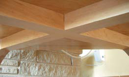
Make sure the base of the unit is well-supported.
The cabinet is basically a big birch ply box with three sections, one up top for the TV, and two down below, one for all the other components, and a smaller, vertical compartment for media storage. The knobs on the front are just for show, but your kids, and maybe your parents, will never tire of twirling them.
Upper Door
I used 1"x6" poplar to build a frame for the upper door. The four frame pieces were glued together with half-lap joints, and then the old-school cathode ray tube shape was cut out.
I used clear silicone to adhere the glass, which fits into a recess that I cut into the backside of the door with the router. You can mount the door using inset European-style cup hinges. A 1-inch wood ball serves as a discreet knob for opening the door.
Lower Door
The lower door is made from ½-inch plywood covered in reproduction antique radio grille cloth (which I ordered from grillecloth.com) to give the illusion that it houses a speaker. Some 3M 777 spray adhesive applied to the front of the door will keep the fabric in place while stapling it to the back, and prevent it from shifting over time.
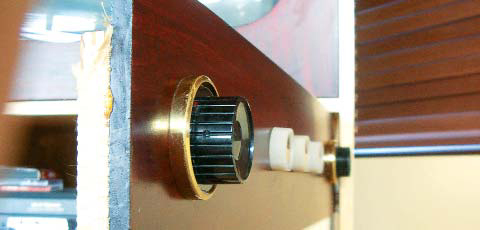
I built a mock “control panel” from ½-inch poplar and mounted it to the top of the door. Knobs salvaged from old radios are hot-glued to anchoring screws that I first attached to the panel. The knob on the left serves as the handle for the lower door. A chrome Chevrolet Belair fender script bought on eBay provides a touch of Hi-Fi to the lower panel and really makes if feel like a speaker grill.
Finish
I finished the main cabinet body and base stand in a clear waterborne acrylic, which provides a durable, clear finish without the yellowing that occurs with polyurethane products.
To create a nice two-tone effect, the poplar upper door and control panel received a dark mahogany color stain with a polyurethane topcoat.
We typically open the upper door for viewing, but occasionally, I’ll cue up a tape of some old black and white commercials, close the door, put on an Esquivel or Henry Mancini record and let it flicker in the background while we have martinis and chat about the space race.
Seattle-based designer Steve Lodefink describes himself as a “broad-spectrum dabbler” who always has to be building something. See everything he makes at finkbuilt.com.
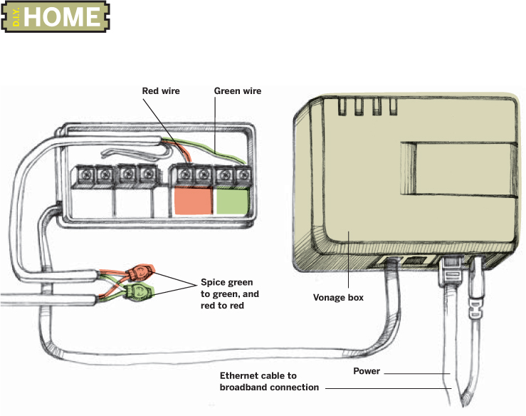
Wiring all your phones to your Vonage account involves terminating the lines at the adapter.
Illustration by Damien Scogin
VOIP PHONE WIRING
Connecting multiple phones to a Vonage connection.
I have no complaints about my Vonage experience so far. The call quality is great. Getting voice mail messages in my email is probably my favorite feature. I can send faxes using a traditional fax machine. I’m able to place calls using a 900 MHz cordless phone or any other standard landline phone. I activated 911 dialing on my account so that emergency dispatchers could determine my location. The only thing that had me perplexed was how I could connect several phones the way I would in a normal landline configuration.
I had a revelation during a walk to the drugstore. The phone wiring in the house could be terminated at my Linksys Phone Adapter the same way the phone company brings their lines to the house and ties in to all the internal wiring of the house. Both scenarios route all the wiring in the house back to a central office. The traditional landline service routes underground or to a pole along the street back to the company while the VoIP method connects to my router headed for the servers at Vonage.
I currently live in an 80-year-old house. The phone wiring has been updated, but the routing of the wiring is a jumble of three different incoming lines routed to different sections of the house. This didn’t matter to me when I moved in because we don’t have a landline phone. In newer houses, this won’t be a problem because all phone wiring should terminate at a central location.
Most home phone wiring is made up of two pairs of wires: red/green and yellow/black. In most cases, the primary line you’ll want to connect to route your VoIP service throughout the house is the red/green pair. If the house was wired using Category 5 cabling, green might be replaced with white-with-blue-stripe wires and red with blue-with-white-stripes. The yellow and black wiring pair will not be needed.
Required Tools and Supplies
Before starting, I needed a few supplies from the hardware store. I purchased a roll of Category 3 cable, a box of 3 port telephone splice connectors, and a phone wire junction box with a modular plug. You could get by without using the junction box, but I’m lazy and don’t enjoy connecting RJ-11 ends to raw wire. The junction box makes it easy to quickly connect your household wiring to the phone adapter. Note: If you plan on connecting the VoIP phone adapter directly to a wall jack, you probably won’t need these supplies.
Several tools are also required. To make the connections, you need a Phillips screwdriver and wire strippers. To finish up, you may want a cordless drill to fasten the junction box and phone adapter to the wall, as well as some coaxial cable straps to router your Ethernet cable along the wall between the phone adapter and your router. Make sure there’s an outlet in close proximity to your phone wiring (to power the phone adapter) or get an extension cord long enough to reach.
Making the VoIP to Cat 3 Connection
First, find the location where external phone lines come in to your house. Determine which lines are internal and which lines route back to the phone company. Disconnect the phone lines coming into the house from the phone company because they might cause noise on the line (or damage the VoIP adapter), and they aren’t being used anyway. Word of Caution: Do not attempt this if you still have an active line with the phone company; it will cause your landline service to cease functioning.
Connecting VoIP via a Wall Jack
If your phone lines all originate on the same copper pair from the phone company, this is potentially your stopping point. With the lines from the local phone provider disconnected, simply plug the VoIP adapter into any wall jack in your house and you should be able to make calls from any of the other wall jacks in your house.
Connecting VoIP at the Origin
Depending on how your home is currently wired, you may need splice connectors to combine all of the various ends throughout the configuration to a single wire that ultimately connects to the junction box. An alternative is to connect each individual line to the junction box. Red wires connect to red wires; green connect to green.
Once all the internal wiring is connected, plug in the phone adapter, connect the Ethernet cable to the appropriate port on the adapter, and connect the RJ-11 modular plug from the junction box to the phone adapter.
Test your connections by plugging a phone into one of the wall jacks in your house. If you get a dial tone, you’re probably set. It’s not a bad idea to place a call to your cell phone just to make sure everything is working.
The final step is to mount the junction box to the wall with the two bundled screws, secure the VoIP phone adapter so it won’t come unplugged accidentally, and fasten the Ethernet cable to keep it out of the way.
Avoid Power Surges
VoIP phone adapters are susceptible to power surges due to lightning strikes, just like a modem might be. To protect your phone adapter, use a surge protector for the power brick and route the phone wiring through the surge protector in reverse. Connect the wall side of your phone connection (the part coming out of the junction box) to the phone/modem port on the surge protector. Connect the VoIP phone adapter to the line side of the surge protector.
Troubleshooting
It’s a good idea to test your connections by placing a call to the VoIP phone number. For my tests, I used my cell phone so I could quickly verify the call.
Jake Ludington is the author of Podcasting Starter Kit (PodcastingStarterKit.com) and hacks media gadgets from his home in Seattle, Wash.
Old school file sharing: Making a duplicate record by casting it in plastic.
RECORD CLONING
Make a plastic cast of an LP or 45.
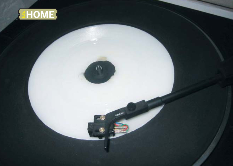
Let’s make a copy of Marvin Gaye’s classic song What’s Goin’ On. Instead of going to our computer and burning an MP3, we’re going to be making a copy of a 45 record. To understand how we can do this, you have to know how a record works. A record is just the physical embodiment of sound etched into the surface of a flat piece of soft material. What we’re going to do is make a copy of those grooves onto a much harder material by making a mold and using that mold to make a plastic casting.
Molding
First, make a form to hold both the record and the molding material you want to use. I built a simple box out of wood that I am setting on a sheet of glass (Fig. 1). Next, you need to choose something to make the mold with. Silicone is a good choice because it can pick up the smallest of details. There are many kinds of silicones, but make sure that you buy one that does not require a vacuum chamber (unless you have access to a vacuum chamber). I used Smooth-On OOMOO 30 to make my mold because of its excellent self-degassing characteristics (smooth-on.com/liqrubr.htm).
Once you have built the form, you need to put clay around any gaps that the silicone might get through (Fig. 2). Modeling clay works well for this because the silicone doesn’t stick to it. Next, you need to apply a release agent to your form. There are several universal release sprays available that work well; however, if it is a very porous material such as wood, you should use petroleum jelly. Coat the inside of the mold and lightly brush it to assure there are no high spots. Use a bubble level to get your form perfectly level.
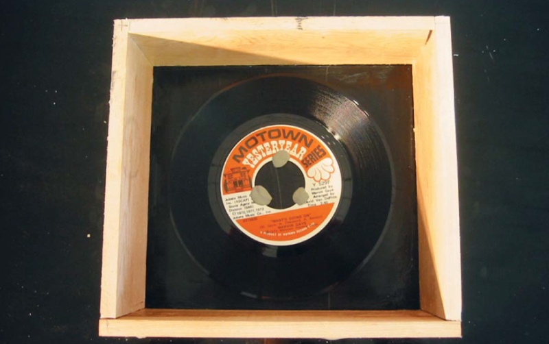
Fig. 1: Place the record you want to duplicate in a box that has been taped up along the corner edges to prevent leakage. You’ll then pour enough liquid silicone into the box to cover the record. After the silicone cures, you’ll use that to make as many plastic castings of the record as you desire.
Put the record on the bottom of the box with the side you want to copy facing up. Use clay to affix and weigh down the record when you begin pouring the silicone.
Mix up your silicone following the manufacturer’s directions. Slowly pour the silicone over the record assuring that no air bubbles remain in the record grooves. Gently tap the side of the molding form to dislodge any air bubbles. Wait until the rubber has cured.
Remove the original record from the mold being careful not to get dirt in the mold or touch the grooves of the silicone mold. You should be looking at an exact reversed copy of your record.
Casting
Now that we have a mold, our next step is to cast a copy. It’s a good idea to use a high performance plastic as the casting material; this way, your copy will be much more durable than the pressed wax original. I used Smooth-On Task 4 for the casting — it has a higher degree of wear resistance than normal casting plastic. Because silicone already has significant self-release properties, I am not applying a release to the mold so that I can get the most accurate representation of the grooves on the record.
BEWARE: This technique can backfire; silicone sticks to some casting materials.
Level the mold and carefully pour the plastic after mixing it according to the manufacturer’s instructions (Fig. 3). Make sure there are no air bubbles on the grooves of the mold. If the mold is level, the plastic should stay in the mold and not run over (Fig. 4). Gently tap the mold to dislodge any air bubbles.
Wait for the plastic to cure according to the manufacturer’s directions. If everything went well, you now have a super durable copy of your favorite record (Fig. 5) and the mold to make as many more as you want!
Dan Mikesell lives and works in New York City where he is a professor and co-founder of Moddities toy design.
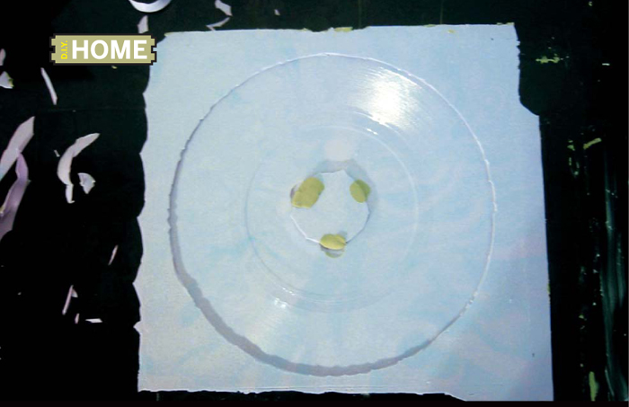
Your silicone mold (above) is a reverse copy of the record. You make the mold by placing the record in a wooden box and pouring silicone over the record (Fig. 2). You’ll then pour plastic into the silicone mold. Be sure to allow the plastic to cure (Figs. 4 and 5) before playing your duplicate!
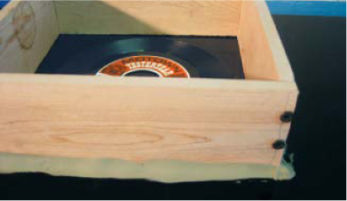
Fig. 2
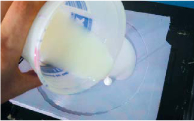
Fig. 3
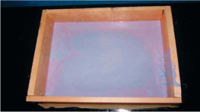
Fig. 4

Fig. 5