R-TRONIC TOY MUSIC SEQUENCER

Photograph by Garry McLeod
BABY BEATS
This simple sequencer lets babies play with shapes, sounds, and lights, while it also teaches older kids the basics of electronic music — and secretly you’ll have lots of fun with it yourself.
I wanted to make a unique present to give my daughter for her first birthday, a musical toy that she could sit down and play with immediately but that would also become more educational for her in a few years. So I built her the R-Tronic 8-Bit, a simple music sequencer that lets you build up, play back, and edit musical patterns. It uses wooden shapes as buttons and LEDs instead of fancy displays.
I started on the project 3 months before my daughter’s birthday, programming a Picaxe microcontroller with a speaker on a breadboard, using just enough software to make the sequencer’s 4 noises. Then I added 4 switch inputs to trigger the sounds, followed by 12 LED blinkies. I ported the tangled breadboard circuit to a neat printed circuit board, and finally built the wooden frame and fit the electronics. The final wiring was completed the night before my daughter’s birthday party.
If I had any worries that she wouldn’t like the R-Tronic, I needn’t have. As soon as she saw it, she knew just what to do.
Set up: p.127 Make it: p.128 Use it: p.133
Brian McNamara ([email protected]) lives in a small town near Canberra, Australia. By day he works at a university designing and repairing biological research equipment; by night he designs, hacks, and bends kids’ toys and musical instruments.
ANATOMY OF A SEQUENCER
The R-Tronic loops sounds in sequences that are 8 beats long. LEDs along the top flash in series to show which beat it’s on.
Push one of the shape pegs, and it adds its corresponding sound into the repeating sequence, at the current beat, overwriting other sounds (or erasing it like a toggle if the same sound is already there).
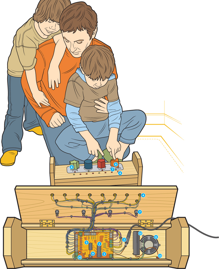
Illustration by Timmy Kucynda
➊ Picaxe-28X microcontroller programmed in BASIC to read input from shape pegs and generate output to LEDs and speaker.
➋ Audio jack provides micro-controller programming port.
➌ Crystal generates oscillations used by microcontroller for sounds and timing.
➍ Sequence LEDs show your place in the 8-beat sequence.
➎ A 3-to-8 decoder lets 3 microcontroller pins run all 8 of the sequence LEDs.
➏ Wooden shape pegs push switches to trigger 4 sounds.
➐ Shape peg LEDs indicate the shape peg associated with the current sound.
➑ The microcontroller has only 3 input pins available for the 4 pegs, so the star (4th) input combines the triangle and pentagon inputs. (The chip’s 4th input pin is needed as a general interrupt.)
➒ 8-pin operational amplifier (op-amp) boosts sound output from the microcontroller to drive the speaker.
➓ Multi-turn potentiometer adjusts the audio volume.
![]() Speaker plays sounds.
Speaker plays sounds.
![]() Three AA batteries in a holder power everything.
Three AA batteries in a holder power everything.
![]() On/off switch
On/off switch
SET UP.
Photography by Brian McNamara
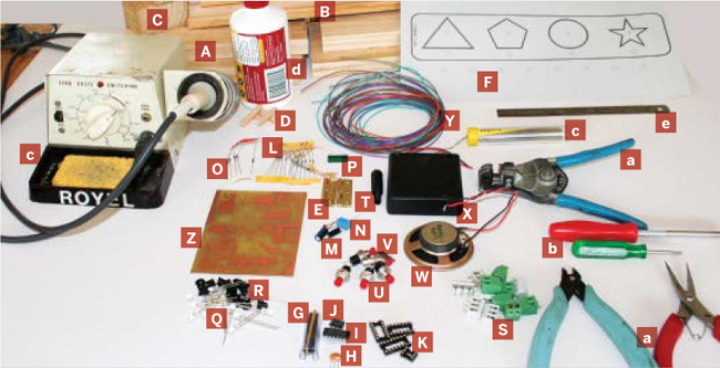
MATERIALS
[A] Lumber, 5"×¾"×48" or similar size I used pine.
[B] Wood molding, 2½"×½"×32" long
[C] Wood block, 13/8" thick to cut 4 different-shaped blocks. Or substitute pre-shaped blocks.
[D] Wood dowel, ¼"×4" long to make four 1" pegs
[E] Hinges (2) with screws
[F] Silver foil label paper, 8¼"×10¾" $8 from desktopsupplies.com, #68000-10
ELECTRONICS
[G] Picaxe-28x microcontroller $9 from world-educational-services.com
[H] Crystal 4MHz resonator comes with microcontroller
[I] 74HC138 3-to-8 line decoder from mouser.com, part #512-MM74HC138N
[J] LM386 power amp RadioShack #276-1731
[K] IC holders: 16-pin, 8-pin, 14-pin (2), and 3-pin strip (optional)
[L] ¼W resistors: 10Ω, 330Ω (12), 4.7KΩ (2), 10KΩ (5), and 22KΩ (2)
[M] 0.1μF capacitors (2)
[N] 250μF electrolytic capacitor
[O] 1N4001 diodes (5) RadioShack #276-1101
[P] Potentiometer, 10KΩ multi-turn
[Q] Colored LEDs: white, amber, red (4 each)
[R] LED holders (12) RadioShack #276-079
[S] Terminal block connectors: 2-pin (5), 3-pin (6)
[T] Stereo jack, 3.5mm
[U] Momentary button switches (4) RadioShack #275-1571
[V] SPST switch for on/off switch
[W] Small speaker Mine came from an old computer.
[X] 3×AA battery holder and clip, with 3 AA batteries
[Y] Stranded wire, 22-gauge Multiple colors make it easier.
[Z] R-Tronic printed circuit board Use the Gerber files at makezine.com/13/sequencer to make one, or send it to a fabrication shop. If someone coordinates a shared bulk order in the discussion area, they’d be much cheaper. You can also email me, and if I have extras I can sell you one for about $18.
[NOT SHOWN]
Self-tapping mounting screws (7) for PCB, speaker, and battery
Screw for securing lid
Cable ties
Beeswax
Food dyes or other nontoxic paints or stains
Heat-shrink tubing, 1/8" and 1/16"
TOOLS
[a] Wire cutters, strippers, and pliers
[b] Screwdrivers
[c] Soldering iron, solder
[d] White glue
[e] Ruler
[NOT SHOWN]
Saw, hobby knife
Chisel with mallet or hammer
Drill with 1/16", 7/32", ¼", and 5/16" bits
C-clamps
Pencil, marker, paper, tape
Small brush and bowls
Picaxe serial programming cable $7 from sparkfun.com, #PGM-08313
PC with serial port
MAKE IT.
BUILD YOUR BABYTRONIC SEQUENCER
Time: 3–4 Weekends Complexity: Moderate to Difficult
START ≫
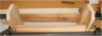
1. MAKE THE WOOD FRAME AND PEGS
I used a 5"×¾"×48" plank and some 2½" molding, but your box can differ, as long as the electronics fit.
1a. From the plank, mark and saw two 8" lengths (for the ends) and two 16" lengths (top and bottom). From the molding, mark and saw two 16" lengths, for the front and back. Trim the 2 top corners of each end piece: mark 1" in and 1" down from each corner, rule a line between them, and cut to shape.

TIP: The molding’s cut-away profile allows you to open the top of the finished box easily. Instead of molding, you could use a router to make your own pattern on the front piece.
1b. Mark a line 2½" up from the bottom of each end piece. Align the bottom edges of the front and back pieces with the ruled lines, and the outside surfaces of the front and back with the ends’ edges. Glue and clamp the 4 pieces together. Allow glue to dry before removing clamps.
1c. Glue and clamp the bottom piece onto your frame, flush with the front and back pieces. Let dry before removing clamps.
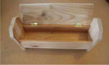
1d. On the top of the back piece, mark 2" in from each end then mark the width of your hinges farther in. Saw and chisel between the marks to make notches for the 2 hinges.
TIP: Wipe off excess glue with a damp cloth; it’s much easier wiping it off now than sanding it off later.
1e. Hold the hinges in place to mark the screw holes on the back piece. Drill 1/16" pilot holes and screw the hinges on. Hold the top piece (lid) against the frame, then mark and drill pilot holes and attach the hinges.

1f. Make sure the lid moves up and down freely, then remove it with the hinges attached. Sand all edges of the lid and frame, removing any excess glue, then seal or paint the wood with something nontoxic (I rubbed it with beeswax). Reattach the lid, and your frame is finished.
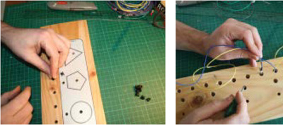
1g. Mark and cut 4 shapes out of wood. I made a triangle, pentagon, circle, and star from a block 13/8" thick.
NOTE: I cut my own shapes, but you can also use pre-shaped wooden blocks.
1h. Paint and seal shapes with nontoxic products. I used food dye to stain, then beeswax to seal.
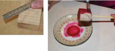
1i. Drill 7/32" holes in the center of each shape, about halfway through, then glue a 1" piece of ¼" dowel into each. Allow the glue to dry.

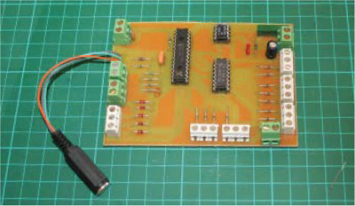
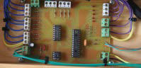
2. POPULATE THE CIRCUIT BOARD
2a. Fit and solder the resistors and diodes to the board. Be sure to fit the diodes in the correct direction.
2b. Solder on IC sockets for the 28-pin microprocessor (I used two 14-pin holders end-to-end), for the 16-pin 3-to-8 decoder, and for the 8-pin audio op-amp. Add the capacitors, potentiometer, and crystal (in an optional 3-pin socket strip).

NOTE: I designed and used a custom circuit board. You can also use plain breadboard and follow the schematic, but the wiring will be dense. Either way, refer to the diagrams at makezine.com/13/sequencer.
2c. Attach the terminal block connectors around the perimeter of the board and plug the microprocessor, op-amp, and decoder chips into the IC sockets.
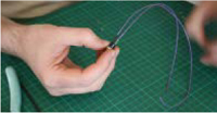
Solder the 3 wires for the programming port onto the 3.5mm audio socket. Now solder the wires to J1 on the PCB. The tip of the socket is soldered to the lower pin on the PCB, and the ring (middle) of the socket is soldered to the middle pin on the PCB. The sleeve (inner contact) on the socket is soldered to the top pin on the PCB. Screw the backshell onto the 3.5mm audio connector.
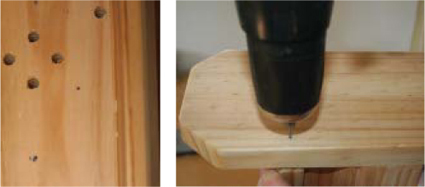
3. DRILL THE FRAME
3a. Print the lid template from makezine. com/13/sequencer. Unscrew the lid.
Trim the template, center it on the lid panel, and tape it in place. Then drill ¼" holes through the panel for each of the 4 shape pegs and the 12 LEDs, as marked on the template.

3b. Using a 5/16" bit, drill back up from the underside of the panel most of the way through the 12 LED holes, leaving a thin fillet of wood. This lets the LED holders latch correctly.
3c. For the speaker, drill four ¼" holes through the bottom of the frame on the right-hand side. Drill another ¼" hole in the bottom-right corner for the on/off switch.
3d. Drill a 1/8" hole in the right end piece, in line with the lid. This is where we’ll add a screw later for securing the lid closed.
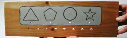
3e. Print the template from Step 3a again, this time on silver foil label paper, using a laser printer. Use a hobby knife to cut out the outline and the holes for the 4 shape pegs and their 4 LEDs. Peel off the sticker backing and affix the label to the panel.
4. POPULATE THE TOP PANEL
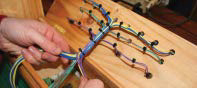
4a. Solder 14" lengths of 22-gauge wire onto the legs of each of the 4 button switches, then insulate the connections with heat-shrink tubing.
4b. Trim the legs of all 12 LEDS to about ¼", then solder 14" lengths of wire onto each, insulating with heat-shrink. Use different colors for the anodes and cathodes so they’re easy to identify later. The anodes (+) customarily have longer legs.
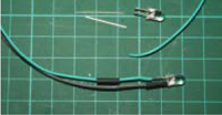
TIP: Heat-shrink tubing strengthens the mechanical connection as well as guarding against short circuits.
4c. From the top side of the lid, fit the 12 LED holders into the LED holes. From the underside of the panel, clip the LEDs into the holders. You may need to use a small screwdriver to snap them into place. I mixed white, amber, and red LEDs to look nice, following no particular pattern.
4d. Continuing on the panel underside, screw the momentary switches into the ¼" holes behind the shape template. Use a black marker to mark each switch’s wires so you can tell which is which when you connect them later.

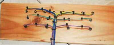
4e. Arrange cable ties around the wires to form a neat loom. This will feed down into the bottom of the box, where the circuit board sits.
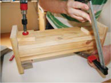
5. FIT THE ELECTRONICS AND FINISH THE WIRING
5a. Center the PCB in the bottom of the box. Mark and drill mounting holes for it in the bottom panel, but don’t mount it yet. You can also drill the board itself, but I positioned the holes so that 4 screws would hold it at the edges. Position the battery holder clip and speaker next to the PCB, then mark and drill mounting holes for those.

5b. Solder the red wire from the battery holder onto one side of the on/off switch. Solder a free wire onto the other side of the switch. Glue the switch into its hole, and clip in the battery holder.
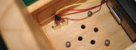
5c. Connect wires from the speaker, battery holder, and on/off switch to the screw terminals on the PCB (refer to TB1 and TB7 on the wiring diagram).

5d. Screw the lid back onto its hinges. Follow the wiring diagram and split the loom into 3 parts, routing connections to each terminal row. Work your way around the board, trimming, stripping, and terminating all the wires. Use additional cable ties to keep things neat. Note that for the LEDs’ positive connections and the peg switches, 2 wires go into each screw terminal.
5e. Have a good look at your wiring to confirm that everything is in place, then mount the circuit board with the screws and load 3 AA batteries into the holder.
6. PROGRAM THE MICROCONTROLLER AND TEST
Finish the project by programming the microcontroller and testing the sequencer, following the instructions at makezine.com/13/sequencer.
FINISH X
NOW GO USE IT »
USE IT.
PLAY, BABY, PLAY
The 8 sequence LEDs represent 8 time slots that can hold sounds. When one of the LEDs is lit, if a sound is triggered using one of the shapes, it will be repeated each time that LED lights up.
Each of the 4 shapes represents a different sound. When you press a shape, the sequencer will remember what slot number (1–8) you were up to and which sound was triggered, and it will play that shape’s sound each time that slot is cycled through. This lets you build up a sequence of sounds one at a time, up to a maximum of 8 in the sequence.
You can change the sequenced sounds by pressing a different shape during any time slot, overwriting the previous choice. Individual sounds can be cleared from the sequence by pressing the same shape during that slot, a bit like a toggle switch. Or you can clear the entire sequence from memory and start from scratch by turning the R-Tronic off and on again.
SUGGESTED MODIFICATIONS
This project is just asking to be hacked. The programming for the Picaxe microcontroller is in BASIC, so you can easily edit the file R-Tronic 8-Bit.bas to change the sound effects for each shape. You could also associate additional sounds for when more than one shape is pressed at the same place in the sequence. And the wooden case simply holds the electronics, so you can be as creative with it as you want.
The shape pegs on my R-Tronic are interchangeable and fit into each other’s slots. The sticker is just a guide, and it’s actually the position rather than the shape that determines the sound. For kids older than 1 or 2, it would be great to make a version of the R-Tronic that only triggers a sound when the shape matches the sticker underneath. Keyed peg holes with matching peg shapes are an obvious way to do this.

Photograph by Sam Murphy
RESOURCES
![]() Watch a short video of the R-Tronic in action at makezine.com/go/rtronic.
Watch a short video of the R-Tronic in action at makezine.com/go/rtronic.