Photography by Gene Scogin
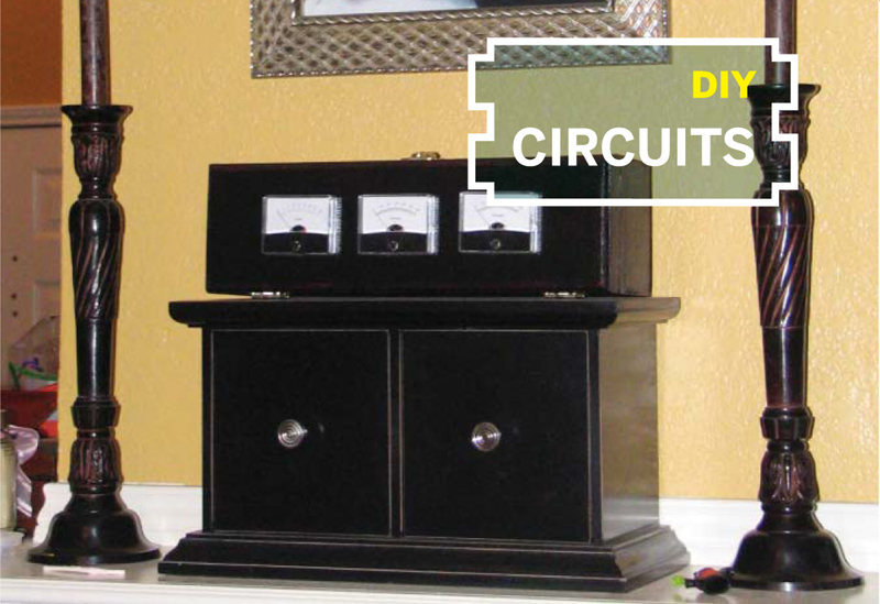
ANALOG AMP METER CLOCK
 Elegant timepiece marks the hours with needle meters.
Several years ago I had the idea of making an analog clock that used voltmeter-style needle gauges rather than a standard dial. A few weeks ago I finally made one, using an Arduino board and 3 current meters from a local electronics store. I built it up in stages, starting out with a single meter that displayed just seconds, then adding hour and minute meters, adding buttons and programming to make the time settable, and finally building it into a nice box. Here’s how I did it.
Feeding the Meter
The Arduino board has 6 outputs that can drive analog values using pulse width modulation (PWM). This means they simulate output voltages lying in between binary high and low (0V and 5V) by cycling rapidly between the two for varying time ratios; for example, a 2.5V output would be simulated by being on for exactly half the time. I found that the Arduino’s pulse frequency was fast enough (490Hz) and my meters were slow enough that you could drive them directly from the board’s outputs without the needles vibrating; you don’t need a capacitor to smooth out the signal.
I was only able to find ammeters and not voltmeters, so I needed to put a resistor in series with the meter to limit the current. Ohm’s law states that to get 1mA of current with a voltage of 5V, you need 5,000Ω of resistance. To allow for normal variations in components, I assembled this resistance by putting a 4,750Ω resistor in series with a 0Ω to 500Ω potentiometer. To set the range for each meter, you first zero it with the adjustment screw on the meter itself, then adjust the pot to set its high point.
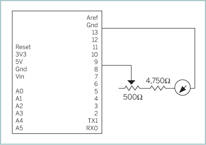
The microcontroller output pin runs through adjustable resistance and then to the seconds meter.
Making It Tick
Once we have our meter hooked up, we can write a simple C program to make it count 60 seconds over its full range every minute. The analogWrite() function takes a value between 0 and 255 and the index of an output pin, and sets the output for the specified pin to a PWM value between 0V and 5V.
To track the seconds, the program runs a continuous loop that calls millis(), a built-in Arduino function that returns the number of milliseconds since the board was last powered up. The value returned is compared with the millis() value from the previous loop, and the difference is added to the running total of seconds, which in turn updates the display.
When the seconds wrap around, the code resets the running total to 0 and adds the remainder. The code also handles another special case, when the value returned by millis() itself rolls over, after about every 9 hours of uptime.
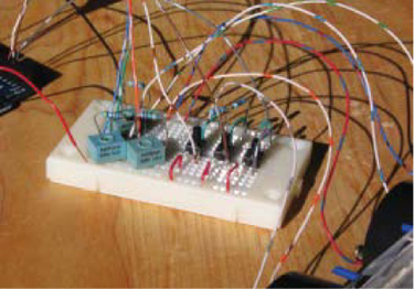
The breadboard carries 3 identical circuits running in parallel, for the hours, minutes, and seconds meters.
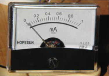
Original ammeters showed a scale between 0 and 1 milliamps.
I used the Arduino’s pin 11 to drive my newly programmed seconds meter. Then I went on to programming and driving the hours and minutes meters in a similar fashion, using pins 9 and 10. The wiring for each meter is exactly the same: the microcontroller output pin connects to the potentiometer in series with the resistor, which then leads to the meter. All the code for this project, along with wiring diagrams, is available at makezine.com/13/diycircuits_clock.
Setting the Time
To make our clock useful, we need a way to set the time after we power it up. To do this I used 3 switches. One cycles the clock through its 4 modes (normal, set, all-low, and all-high — explained later), one increments the hours, and one increments the minutes. To get a proper reading from digital inputs, we need a pull-up resistor between each input pin and +5V. The Arduino’s microprocessor has these conveniently built in, but you need to explicitly activate them by declaring the pin as input with pinMode(b1pin,INPUT) and then calling digitalWrite(pin,HIGH).
Because the program runs through its main loop many times each second, we assume that a single push of the button will be read multiple times. To handle this, I have a variable for each button that keeps track of its state. Also, when the program first detects that a button’s state has changed, it delays for 20 milliseconds to wait out any signal bounce from the switch.
The mode switch moves the clock between 4 modes: normal, set time, all meters low, and all meters high. Normal mode shows the time, set mode lets you change it, and the all-low and all-high modes set the 3 output pins to 0V and 5V, respectively, for calibrating the meters. The code continues to keep track of the current time in all modes, unless it’s reset. I am considering adding additional modes to the clock, such as alarm, stopwatch, and timer.
Making the Scales
The scales on the meters as purchased read from 0mA to 1mA, but for the clock to be readable, we need scales that go from 0 to 24 for the hours and 0 to 60 for the minutes and seconds. Doing this ended up being one of the hardest parts of the project.
I started by disassembling one of the meters and scanning the printed panel with the scale. Then I used the measuring tools in the Unix drawing program Xfig (xfig.org) to measure the image’s distances and angles. One complication was that the scale isn’t based on a simple circle arc; it’s compressed vertically so that the ends of the scale lie farther away from the needle’s pivot point than the middle.
To generate the new scales, I wrote a program in Tcl (tcl.tk) that takes a set of distances and angles that describe a scale, calculates its component lines and curves, and outputs an image file in Xfig’s native format. I read this file into Xfig and used it to generate a printable PostScript file.
The only problem was that the finest line that Xfig could draw was thicker than I wanted, so I edited the PostScript by hand to make the line thinner before printing it. Once I printed out the new scales, I cut them out and used spray adhesive to stick them on the plates (Figure A).
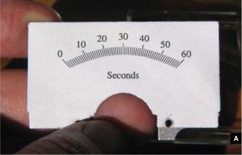
Fig. A: The seconds meter scale displays 60 with an input of 1 milliamp.
To help line up the scales on the plates, I printed extra marks where the screw holes were. And so that the original scales would not show through the paper, I put the new scales on the backs of the plates, which were blank (and symmetrical).
Boxing It Up
This is the type of project that needs a good box, to display the meters and conceal the wires and such. My wife suggested that a nice wooden box would look good on the mantle, and we chose one at a local craft store.
Mounting the meters meant drilling a wide central hole for the back of the meter itself, surrounded evenly by 4 small holes for the mounting screws. I made a paper template as a guide (Figure B, previous page) and drilled accordingly, but it was hard to get the mounting holes accurate enough, so I used a larger bit and a keyhole saw to clear out enough space for them to fit (Figure C). The meters all fit tightly in the central holes, so I didn’t bother putting nuts and washers on the mounting screws (Figure D).
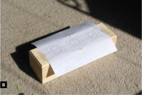
Fig. B: Paper template for cutting holes in the box.

Fig. C: Holes in the box, with some holes sawed out into slots to fit screws.
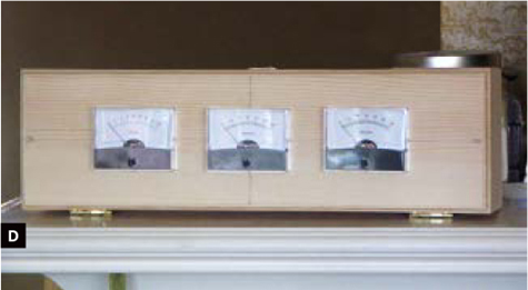
Fig. D: The meters with their new scales fit into the box.
For the power source, I considered putting batteries in the box, but the Arduino pulls 20mA–30mA, so even with D cells, they would need to be changed about every 5 weeks. Instead I decided to use a wall wart and ran the cord through a hole in the back of the box. The buttons for setting the clock and changing modes I left on the breadboard inside.
Finally, I wanted the box to be an aged black, to match our furniture. I accomplished this effect by first putting down a coat of red paint and allowing it to dry (Figure E). I then followed it with black and lightly wiped the wet paint off the edges, exposing small amounts of red underneath (Figure F).
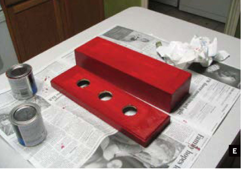
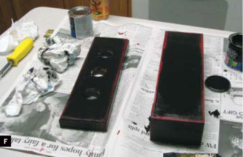
Fig. F: Black paint partially rubbed away along the edges, exposing the red undercoat for an antique effect.
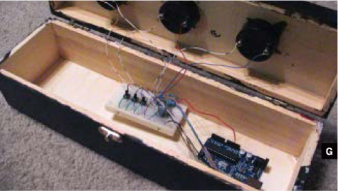
Fig. G: Finished amp meter clock with the lid open to show the circuitry.
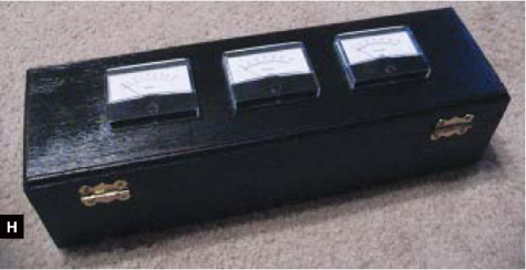
Fig. H: Clock displaying the analog to a blinking 12:00.
The end result is a unique clock and a great conversation starter that can be displayed prominently in my home, and now in yours, too!
Gene Scogin is a computer programmer who enjoys a variety of hands-on projects.

Photograph by Sam Murphy
TV-B-GONE HAT
 Turn off TVs by just looking at them.
“Hey, you mind turning that thing off?” Simple enough question, but I got tired of people looking at me like I’m from Mars. When a TV is on in the room, I can’t think. I just stare at the thing and drool.
So I invented TV-B-Gone, a key chain that stealthily turns off just about any television. When the TVs turn off, people turn on, engage in conversation, read, eat, and perform all sorts of human activities. Peace happens.
I recently teamed up with prolific kit maker Limor Fried to create a $20 kit version of the original TV-B-Gone key chain. This version works up to 40 yards away, and it’s totally hackable; the entire project is open source and documented at ladyada. net/make/tvbgone. Here’s how I built one into a baseball cap that lets me look at almost any TV, touch the top, and watch with glee as it shuts off.
How TV-B-Gone Works
TV remote controls all work the same way: by transmitting coded patterns of 940nm wavelength infrared to the television’s remote control receiver, somewhat like sending Morse code with a flashlight. The receiver watches for blinking IR, and when it sees patterns it recognizes, performs the corresponding functions on the TV. To avoid accidental triggering by reflected light in the room, receivers only respond to IR light that pulses at a specific carrier frequency.
For our TV-B-Gone, we don’t care about couchsurfing functionality; all we need is the code for turning a TV off. (Because remotes have just one on/off button, this is the same as the code to turn it on, and the TV’s current state determines which new state to toggle to.)
For example, to turn off a JVC TV, you blink the pattern shown in Figure A using a carrier frequency of 54kHz. The entire sequence lasts only a tiny fraction of a second, so there’s no perceivable delay.

Fig. A: On/off infrared blink sequence for JVC brand TV remote controls.
Different manufacturers’ IR standards vary, but they all use rapid blinking of an even faster carrier frequency. TV-B-Gone transmits the on/off button codes for most TVs, one right after the other. So it works like other remotes, but with just one button.
1. Assemble the kit.
First I built the TV-B-Gone kit itself. I already knew how to do this, but you can follow the excellent instructions at ladyada.net/make/tvbgone.
2. Install the switch.
Take out the batteries and unsolder the battery leads from the board. Then bend the 4 legs of the tactile switch apart so they’re flat, and hot-glue the switch to the button on top of the cap (Figure B).
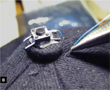
Fig. B: Pull wire-wrap wire through the cap’s fabric to connect the switch on top.
Use needlenose pliers to push some of the wire-wrap wire through the hat fabric near the button. Pull enough wire through on the underside of the hat to reach the end of the visor. Repeat using a second piece of wire, then solder the wires to 2 of the switch’s legs on the same side, clip off the other 2 legs, and cover the soldered joints with 1/16" heat-shrink tubing.
If you use a lighter, be careful not to place the tubing (or the hat) directly in the flame. Hold the flame just above the tubing and move it around slowly until it’s fully shrunk.
Use a needle and thread to sew the 2 wires to the inside of the hat. I used 5 loops for each, tying them off with a square knot (Figure C). Alternatively, you can also use hot glue.
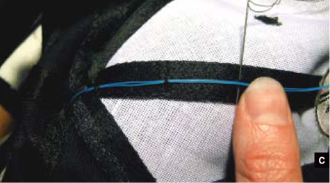
Fig. C: Sew the switch wires along the inside seam from the top button to the brim where the circuit board is glued.
Position the assembled TV-B-Gone at the edge of the visor of the hat, with the IR emitters just inside the brim, pointing outward. Cut the wires from the hat-top switch so they extend just past the switch button on the circuit board (Figure D).

Fig. D: Trim the wires to just reach the board switch terminals.
Photography by Mitch Altman
3. Install the battery pack.
Center the battery pack under the cap’s dome with its 2 wires facing forward, toward the visor. Hot-glue the battery pack in place, then sew (or hot-glue) its wires to follow the same paths as the switch wires.
4. Install the TV-B-Gone.
Trim and solder the wires to the battery terminals on the circuit board (BATT), red to + and black to -, covering the connections with 1/16" heat-shrink tubing. Trim and solder the 2 wires from the tactile switch and solder them to the 2 connected terminals for the onboard switch (S1). It does not matter which wire goes to which terminal (Figure E).

Fig. E: Solder the switch wires to the onboard switch terminals.
5. Test.
Insert 2 batteries into the holder. The visible LED (LED5) should start blinking. If not, immediately take the batteries out and check that the battery leads aren’t reversed. You can also confirm that all 4 of the TV-B-Gone’s IR emitters are blinking by watching them through a digital camera (most cameras can see IR).
After the TV-B-Gone turns itself off, pushing the button on top of the hat should restart the transmission sequence. If not, double-check the wires running from the hat switch to the board.
6. Final assembly.
Remove the batteries, then cover the circuit board with a 2"-long piece of 1" heat-shrink tubing and shrink it in place. After shrinking, cut little pieces out of the tubing to expose the visible light and the onboard switch.
Hot-glue the covered board to the underside of the visor with the IR emitters facing forward, as before. Finally, use a colored marker or paint to conceal the silver parts of the hat switch (Figure F).
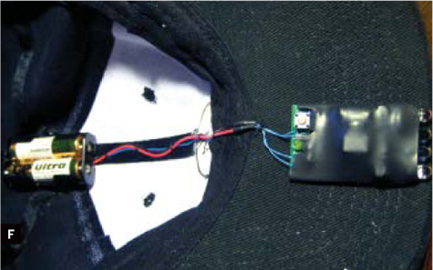
Fig. F: TV-B-Gone and battery pack installed, insulated, and ready to increase the peace.
A Real-Life TV Story
We walk into a restaurant. Nice place — except there are 3 huge-screen TVs blaring from different corners. No one is watching any of them, so off they go. None of the customers even seem to notice, yet the waiter feels obliged to turn them back on.
No problem — off they go again. The waiter calls the manager, who grabs the remote control and turns them on again. Triumphant, they start to walk away. Off go the TVs once more. While they’re standing there, dumbfounded, I switch them all on. Then off. Their shoulders slump in unison, admitting defeat. We enjoy our meal and conversation.
I love my TV-B-Gone hat.
Among other projects, Mitch Altman is currently working on TV-B-Gone Pro, which will turn off TVs from 100 meters, and an open source, commercial version of the Brain Machine he wrote about in MAKE, Volume 10.
Photography by Nick Archer
TRANSISTORIZE YOUR IPOD
 Get vintage sounds from time-warp radio.
Hearing “Monday, Monday” on giant stereo speakers doesn’t pack the emotional wallop of listening to it through the 2¼" speaker of my childhood transistor radio. When the iPod shuffle came out, it hit me: I could wire one of them into a vintage radio and recreate that experience.
I got an old radio from eBay, hooked it up, and it worked! Then I loaded up the iPod with old airchecks from DJs of my childhood, plus old songs and commercials from the same era, and now I can listen just like when I was 12. Everyone I’ve played it for says it’s spooky, like the radio just arrived from the 60s.
Rewiring It
The idea is to route the output from the iPod to the audio input and to the radio’s volume control. Open up the old radio (Figure A, on next page) and remove the guts. Stick the tiny screws to a piece of tape for safe storage. My speaker had a hole in it that caused a buzzing sound at high volume, but here’s an old trick: layer rubber cement over the hole until it’s covered (Figure B). No more buzz!

Fig. A: Transistor radio from eBay with the case back removed.
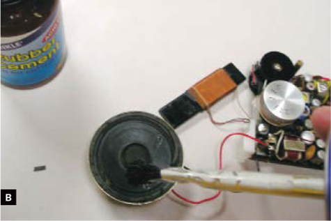
Fig. B: Repair a buzzing, damaged speaker with rubber cement.
Now, prepare the plug that goes into the iPod (Figure C). After unscrewing the back, solder 1 wire to the terminal that connects to the plug’s sleeve; this is ground. Solder two 3.3kΩ resistors to each of the other 2 terminals, and then join the other ends and solder them to another wire. This converts the stereo signal to mono. I put a piece of paper inside the plug to prevent shorting before screwing the shell back on.

Fig. C: Convert stereo to mono by adding resistance to channels and connecting them together.
Drill a hole in the back of the radio case and thread the 2 wires through from the plug. Solder the wires to the 2 exposed tabs on the radio’s volume control.
Attach a 9V battery to the radio’s clip, plug into the iPod, and turn both on (Figure D). The iPod’s sound should come through the radio speaker, and the radio’s volume control should work, but if it works the wrong way, unsolder, and reverse the 2 wires.

Fig. D: The iPod connected and the radio ready for reassembly.
Carefully replace the radio guts back into their case, tuck in the new wires, and reassemble. I hung the iPod on the back of the radio’s leather outer case so I can still take it off to go to the gym, but yours might fit inside the case, at the top, in place of the ferrite antenna. My radio already had a broken antenna wire, so I left it alone.
Programming It
Now go to reelradio.com and airchexx.com, and grab some vintage airchecks from your favorite childhood station. I’ve loaded Bill Berlin from WKDA Nashville, Tenn., Dr. Don Rose from WQXI Atlanta, and various jocks from WKBW Buffalo, N.Y., WEAM Arlington, Va., and WOWO Fort Wayne, Ind. Make an iPod playlist with airchecks, your fave songs, and some old commercials.
Load it up and enjoy! Even the old-school earphone works! Will Apple build these for us oldsters? I hope so, but why wait around?
![]() You can hear the radio in action at makezine.com/13/diycircuits_radio. Keep the volume low, and you can really hear how songs sounded in the 60s.
You can hear the radio in action at makezine.com/13/diycircuits_radio. Keep the volume low, and you can really hear how songs sounded in the 60s.
Nick Archer has been a radio DJ, program director, and disco DJ, and now owns a recording studio in Franklin, Tenn., that does radio commercials, internet audio, and books on tape. His transistor radio has been on non-stop since January 1965. archerproductions.com