Photography by David Simpson
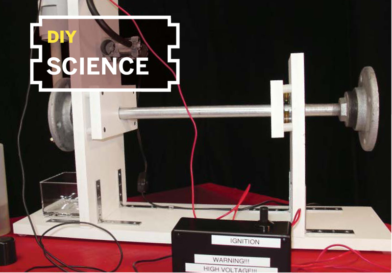
EXPLOSION ENGINE
 DIY internal combustion using Home Depot parts.
A few months ago, some of the cadets in my Civil Air Patrol squadron were stumped by the chapter we were reading on internal combustion engines. The pictures failed to convey what really happens, and even the word “combustion” sounds like what a candle does. Engines are all about explosions, front and center! So we needed to make some explosions and show the students how these blasts get turned into the power that runs cars, airplanes, and weed whackers.
I thought it would be fun to make my Internal Explosion Engine entirely out of parts available at Home Depot, and I did it (almost), basing my design on the classic PVC spud gun. The result has all the parts of an engine and shows how they work together. After building this project, you’ll feel a lot more knowledgeable talking to your mechanic.
Overview
Our combustion cylinder is 2" PVC pipe, and the fuel is butane, which you squirt in manually. The ignition spark comes from a piezoelectric grill starter wired to 2 pairs of screws inside the cylinder. A 12V electric air pump blends fresh air with the butane and flushes out the exhaust.
The explosion forces down a PVC piston and its dowel connecting rod, turning the galvanized pipe-and-flange crankshaft, which rotates 4 or 5 times until balance weights on the flywheel pull it back for the next firing. I made the frame from a PVC composite board that tools like wood, but looks spiffier. A complete list of materials and tools is on page 164.
Construction
Keep everything as square as possible, so linkages work smoothly. If you don’t have a drill press, monitor your drilling angle, and after making a pilot hole, slide the bit back in to make sure it’s straight. If not, correct it, using the next larger bit.
1. Cut the crankcase and base boards.
Cut 3 lengths of ¾"×7¼" (referred to as 1×8) Veranda or Azek trim board: 25" for the base, 23" for the forward crank support, and 11" for the rear crank support. I attached 6 rubber feet to the underside of the base, but you can also do this at the end.
2. Build the crank bearing assemblies.
For each crankcase bearing, we’ll use three 1¼" patio door roller bearings spaced evenly around the crankshaft. (If it didn’t violate “available at Home Depot,” I’d have simply used 2 sealed ball bearings.)
Mark a point on each support centered 7½" up from the bottom, and use a compass or template to draw a circle the width of your crankshaft pipe (mine was 13/16") around each point. Use a protractor to mark 3 evenly trisecting lines around each point.
Using the roller bearings as guides, mark the points where you can mount a bearing along each line so they’ll cradle the crankshaft on all sides. Drill a ¼" hole ¼" deep at each point, then drill out the center to 1" (slightly larger than the crankshaft). To allow the top bearings some play, use the Dremel router bit to extend each top hole up about 1/16", making them oblong.
Cut two 3½"×7¼" blocks of trim board; these will hold the other sides of the bearing shafts. Mark and drill the positions of 3 bearing mount holes and 1 big center hole, just as you did with the supports. Mark, drill, and countersink 4 more holes on each block, ½" in from each corner and large enough for 15/8" drywall screws to drop through.
Time to assemble. Lay the bearing support blocks flat, drilled side up. Sandwich each bearing in its holes (Figure A) with the smaller blocks on top, fitting ¼" nylon flat washers over the shafts on each side. Mark the support blocks below each corner hole, and drill pilots for drywall screws. Screw the blocks together, threading 4 stacked ¾"×½"×1/8" nylon washers onto each, in between as spacers (Figure B). The bearings should spin freely, and each top bearing should have a little up/down play.
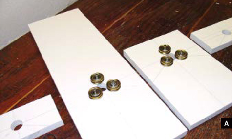
Fig. A: Crank supports with bearings installed, and smaller “sandwich” blocks, ready to assemble.
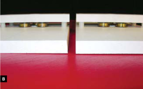
Fig. B: Side view of finished crank bearing assemblies. Bearings are made from metal patio door rollers.
3. Make the cylinder saddles.
On a long piece of the 7¼" trim board, mark 2 lines, 3" and 6" in from one end, then mark the center point of the first line. Cut a 2" hole around the point using a hole saw. Using clamps and a straightedge as a fence, cut along each line to create 2 identical arch-shaped pieces.
Mount the 2 saddles to the forward crank support, on the opposite side from the bearing, using 1½" corner braces. Position one flush with the top and the other 7" down. For traction, line the arches with 1" adhesive tread (Figure C).

Fig. C: Cylinder saddles mounted to front bearing block and lined with adhesive tread.
For the cylinder hold-downs, use 2 lengths of ¾" brass pipe strap. Drill 1/16" pilot holes on either side of each saddle for mounting screws, and do a “dry run” securing the 2" PVC in place (Figure D).

Fig. D: Cylinder test-mounted in saddles with brass pipe strapping hold-downs.
4. Mount the crank bearing assemblies.
Mount the 2 crank bearing assemblies to the top of the base, 6" in from each end, with the bearing sides facing each other. Use a square to make sure the supports are vertical and parallel, and secure them with pairs of 3" corner braces on each side. Offset the braces by ½" so their screws don’t clash (Figure E).

Fig. E: Crank bearing assemblies mounted onto the base.
5. Make the cylinder.
Use the Dremel to cut an exhaust port in the 2" PVC pipe about 11/8" high by 1½" wide, and 5/16" from the end (Figure F). Chamfer the inside bottom of the cylinder to give clearance for the connecting rod.
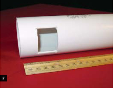
Fig. F: Exhaust port cut into the bottom of the cylinder.
6. Insert the spark points.
Mark the circumference of the cylinder at 11½" and 20½" from the bottom. Through each line, drill 2 pilot holes spaced 120° straight into the center. Screw in 4 drywall screws until the tips of each pair lie ¼" to 3/8" apart inside the pipe (Figure G).
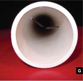
Fig. G. Spark points (drywall screws) form a spark gap inside the cylinder.
Test the points by linking one from each pair together with an alligator clip jumper, then run leads from the 2 free points to the grill igniter. Push the igniter button, and you should see 2 sparks. If not, disconnect, tighten the screws to bring the points closer together, and try again.
7. Mount the cylinder head.
Fit the PVC end cap, or adapter with screw plug, onto the cylinder (the end cap makes a “hemi” style head, while the adapter and plug let you examine the sparking more easily). Secure with 3–4 screws.
Marking PVC Pipe Straight Across

One way to mark a pipe evenly for cutting is to lay it in the corner of a box or drawer, hold a pencil down at the measured marking point, and rotate the pipe underneath until the pencil mark goes all the way around.
Find more tools-n-tips at makezine.com/tnt.
8. Assemble the piston and connecting rod.
Drill two 15/64" holes centered through the 1¼" PVC end cap, 3/8" from the bottom. Precision is important here. The 2" tension pin, which acts as the wrist pin, should fit through and move without binding. Drill a 7/32" hole for the pin, ½" from the top of the 9" dowel; it should fit snugly. Drill a ¼" hole for the crank, ½" from the bottom of the dowel, parallel to the top hole. Attach the piston to the rod using the pin and two 3/8"×5/8" nylon spacers (Figure H).
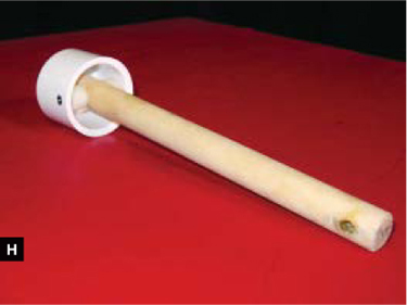
Fig. H: PVC end cap piston connects to the dowel connecting rod with wrist pin and nylon spacers.
9. Make the flywheel and crank.
Tightly screw each of the 2 pipe flange adapters onto the flanges. Thread a 2" flat-head bolt, washer, lock washer, and nut out through one of the mounting holes in one of the flanges. Slide the metal pipe through both bearing assemblies, and slide a ¾" steel washer and 7/8" external tension retaining ring onto each end. Screw on the flange assembly with the bolt (the crank) and attach the other flange assembly (the flywheel) onto the other end (Figure I).
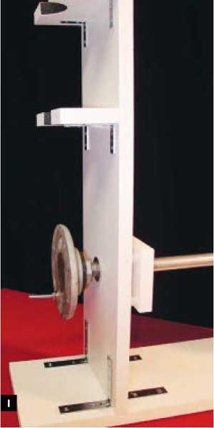
Fig. I: Galvanized pipe crankshaft and pipe flange crank with a bolt running through the connecting rod.
Link the connecting rod to the crank by threading a washer, the rod, another washer, and 2 nuts locked against each other onto the crank bolt. The crankshaft should turn freely and rock the connecting rod and piston. At this point, it’s a floppy mess!
10. Secure the stationary engine components.
Slide the cylinder over the piston and strap it down loosely. Position it so that the exhaust port faces sideways and half of the wrist pin drops below the cylinder at the bottom of the stroke (Figure J). Tighten the hold-downs, but not enough to distort the cylinder.

Fig. J: Cylinder and moving parts installed: piston, rod, crank, crankshaft, and flywheel (not shown).
11. Mount the air injection system.
Remove the guts of a 12V car-trunk air pump and attach a basketball inflating needle to the hose. Drill a 5/64" hole into the cylinder roughly 5/8" below the head, slide the needle into the hole, and fabricate a small saddle out of board that you can zip-tie between the hose and cylinder to keep the needle in place (Figure K). Mount the compressor to the back of the forward crank support using screws, coupling nuts (as standoffs), washers, and rubber grommets. The air hose should lay flat against the support.

Fig. K: Fuel and air injection: Holes for canned butane and an air pump with a basketball inflation needle.
12. Mount the ignition system.
To keep a safe distance from the explosions, I made extra-long leads for the igniter using alligator clips and 9’ lengths of hookup wire. And to avoid the risk of zapping myself, I mounted the igniter inside a small project box. Drill holes for the wires in opposite ends of the box (Figure L) and keep them apart as they snake over to the spark points so the spark doesn’t jump too soon. Connect the wires the same way as when you tested the spark points in Step 6. Your ignition system is now “armed and dangerous.” Label the housing with appropriate safety lingo.

Fig. L: Ignition system: Piezo grill igniter in the project box with holes on either side to keep the leads safely separated.
13. Drill the fuel injection port.
Drill a 1/8" hole in the cylinder about 5/8" below the head. This is where you’ll inject bottled liquid butane into the explosion chamber. Slip a small washer over the bottle’s nozzle to prevent it from sticking to the cylinder.
14. Counterbalance the flywheel.
Weight the flywheel assembly with a bolt, washer, lock washer, and nut combination, so that the piston naturally comes to rest just past the top of the stroke — the optimal position for power delivery.
15. Lubricate the piston.
Using a squeeze ketchup bottle, squirt the thickest clear shampoo you can find into the exhaust port so that it runs around the piston. This helps with compression and lubrication. Catch the overflow in a plastic container below the connecting rod — the engine’s “oil pan.”
Fire It Up!
With all the fanfare of a shuttle launch, follow this sequence:
1. Set the piston to the just-over-top position (the counterbalance weight should take care of that).
2. Plug the air compressor into a car lighter jack and switch it on.
3. Fire a 1-second shot of butane into the cylinder.
4. Wait 15 seconds to let the air and fuel mix.
5. Fire! You should get a good explosion and at least 5 rotations of the crank. Wait 15 seconds for the compressor to replace the exhaust with fresh air, then repeat Steps 3 and 4. Periodically lube the piston with a squirt of shampoo.
Experiment with the duration of the fuel burst and the air/fuel mix time. Slightly shorter or longer may yield a more efficient blend and a better bang!
David Simpson teaches aviation to teenage cadets as aerospace education officer for the Civil Air Patrol in Morristown, N.J. He is also a private pilot, and he began building and flying model airplanes at the age of 11.