
Owen Tanner
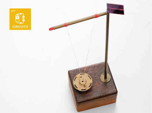
Solar Pendulum
Sunshine is all you need to get this easy-to-build pendulum swinging.
IF YOU’RE STUCK FOR SOMETHING TO DO on a rainy weekend then this might be the perfect thing to build, ready for when the sun comes back out. The pendulum is self-starting, meaning that when light hits the solar panels it’ll start swinging all by itself. There’s something a bit magical about watching it swing ever higher with no visible help, which is the main reason I decided to build one.
The inner workings of my pendulum are built around a circuit that appeared in the book Junkbots, Bugbots, and Bots on Wheels, co-authored by the father of BEAM robotics, Mark Tilden. BEAM stands for biology, electronics, aesthetics, and mechanics, and it’s a style of robot-making that uses simple analog circuits rather than microprocessors (see MAKE Volume 06, page 76).
BEAM bots generally use simple electronic components, and they’re often solar powered. Another hallmark of BEAM bots is that their behavior is usually more complex than their simple components would suggest, and this pendulum is no different.
The pendulum itself consists of a neodymium magnet suspended above a coil of wire using fishing line. Capacitors in the base store energy from the solar panels, which is dumped into the coil below the magnetic pendulum by transistors. The magnetic field generated by the current flowing in the coil attracts the hanging magnet, starting it swinging. With every swing the magnet gets another pull from the coil, lifting it higher and higher.
An LED connected across the coil takes advantage of the back EMF (counter-electromotive force) generated when the moving magnet passes by. This energy is harvested and used to flash the LED with every swing. The cycle continues as long as the sun is shining.
With no batteries to replace, this pendulum will run for years without maintenance.
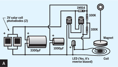
1. Assemble the circuit.
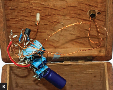
Build the circuit, following the schematic (Figure A). This should be simple if you’ve had any previous soldering experience, as there are only a few components. I’ve gone for a slightly shambolic approach to this circuit (Figure B) as I knew it was going to be hidden away, so feel free to be much neater than me. It doesn’t need to be pretty to work, though, so don’t feel intimidated if you’ve not had much experience building electronic circuits.
To connect the LED, solar panels, and coil, you may want to use crocodile clips rather than soldering, so you can test the circuit before assembling it. I made long extension cords for these parts using twisted pairs of enameled copper wire to allow me to run them through the brass arm and then down through the holes in the base box.
To test the circuit, you can use any 3V DC power supply in place of the solar panels if there’s no sunshine. You should be able to tape a magnet to a piece of thread and, holding it above the coil, trigger the magnetic pulses. This will cause your magnet to start swinging and will also light the LED as it passes back past the coil.
2. Construct the brass arm.
Cut 2 lengths of brass tubing: 30cm for the vertical section of the arm and 10cm for the horizontal section. Clamp the vertical tube in a vise, and drill a 5mm hole 10mm from one end. You’ll run the LED wires through both tubes, via this hole. Be careful not to drill all the way through the tube; if you’re using a drill press, it’s helpful to set the depth stop before drilling to prevent this happening.
Next, join the 2 sections of tubing at right angles by brazing (soldering) them together. If you have a low-powered soldering iron, you may have trouble. Mine is only 25W and it did OK, so anything above that should be fine.
Before soldering, clean the areas to be joined by roughing them up using coarse sandpaper. Sand the end of the horizontal tube, and all around the hole in the vertical tube.
Next, stick some solder onto the 2 tubes before you attempt to join them. This is where the flux comes in. Tackling one piece at a time, liberally apply a coating of flux at the joining point, and then heat the area with the soldering iron while feeding solder into the area. When the tube is hot enough, the solder should begin to flow around the area to be joined.
Once each piece has a coating of solder, they can be brought together and reheated. Clamp the vertical tube to stop it rolling around, and hold the short tube with pliers or thick gloves. You may find it useful to use a blowtorch instead of a soldering iron to gently heat the pieces while you push them together (but be careful, too much heat may discolor the metal).
You’ll now have the 2 pieces joined at right angles (Figure C). If you have masses of solder at the joint, just sand it down nice and smooth.

3. Drill the base.
Position the brass arm and the coil on top of your box so the coil lies approximately beneath the midpoint of the horizontal tube (Figure D). Once you’ve found positions that look right, mark the positions for the holes on the box. As the wire coil has a hole in its center, you’ll probably want to offset the drill hole for this so it’s hidden under the coil.

When you’re happy with the layout, drill a 5mm hole for the brass arm. It should be a snug fit. A smaller drill bit of 3mm can be used to make the hole for your coil wires to go through. Lightly sand both holes to remove any rough edges.
4. Make the pendulum.
My pendulum is constructed using some old brass gears to hide the neodymium magnet. The main gear is 45mm in diameter, with a smaller gear stuck on top for decoration. The magnet and gears are attached using epoxy glue, which is more than strong enough to hold everything together.
For hanging the pendulum, I added a short loop of the enameled copper wire. I simply looped it through the holes around the edge of the gear, wrapped the loose ends back around to secure it, then bent it upward to form a peak in the middle (Figure E). Depending on the weight of your pendulum you may need to use slightly stiffer wire for a hanger, to stop it deforming as it swings to and fro.

![]() CAUTION: When using power tools, always wear eye protection, work slowly and carefully, and follow the operation and safety instructions in the owner’s manual.
CAUTION: When using power tools, always wear eye protection, work slowly and carefully, and follow the operation and safety instructions in the owner’s manual.
5. Wire it all together.
This is the tricky bit. The wires for the LED and solar panels must be threaded through the brass tubing and down into the box.
I found it best to thread the LED wires first as they’re the most difficult. Push them through the short brass tube, wiggling until you can see them come out into the vertical tube.
Next, take a short length of copper wire and make a small loop in the end, creating a makeshift needle (or use an actual needle if you like). Tie a length of cotton thread to this loop and drop your needle down the vertical tube.
Make a slipknot in the thread and slip it around the LED wires; with careful maneuvering you’ll be able to pull it tight around the wires. Now pull the wires down through the vertical tube and push-fit the tube into the base. (I added a decorative disk at the base.)
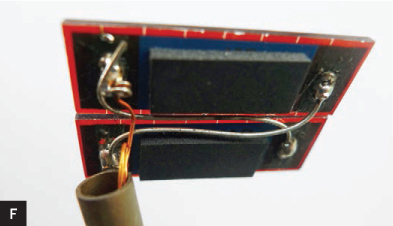
The solar panel wires can then be worked down alongside the LED wires with a bit of jiggling (Figure F).
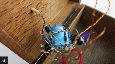
Finally, push the coil wires through their hole and solder them into the circuit, along with the LED and solar panels (Figure G).
6. Hang the pendulum.
Originally I hung the pendulum using the enameled copper wire, but it snapped after constant swinging fatigued it. I switched to fishing line and haven’t had any trouble since.
Tie one end of the fishing line to the brass arm, thread the line through the wire hanger on the pendulum, and then loop it back up over the arm and tie it to itself using a slipknot. This will allow you to make adjustments to the height of the pendulum above the coil.
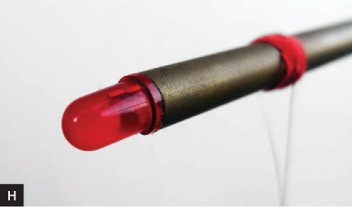
To keep the line from moving around on the brass tubing, wrap cotton thread around the tube many times, on both sides of the line, until you’ve built up a tight and secure lashing, then tie off the thread and trim the knot (Figure H).
If the slipknot on your pendulum isn’t tight enough, add a drop of super glue to fix it in position when you’re happy with the height.
Operation and Troubleshooting
To operate the pendulum, simply set it in the sunshine on a sunny day. If the pendulum doesn’t start moving, try the following:
![]() Adjust the positioning of the magnet. Hang it so that it’s not aligned directly above the coil. It should be off to the left or right slightly, but not so much that the magnet doesn’t overlap the coil at all.
Adjust the positioning of the magnet. Hang it so that it’s not aligned directly above the coil. It should be off to the left or right slightly, but not so much that the magnet doesn’t overlap the coil at all.
![]() Experiment with the vertical distance between the coil and the magnet.
Experiment with the vertical distance between the coil and the magnet.
![]() Check the connections of the transistors, which handle the switching of the coil.
Check the connections of the transistors, which handle the switching of the coil.
![]() Make sure there are no other magnetic materials around where you’re building and testing the circuit that might be causing it to trigger. Something like that is easy to overlook and can cause hours of head-scratching.
Make sure there are no other magnetic materials around where you’re building and testing the circuit that might be causing it to trigger. Something like that is easy to overlook and can cause hours of head-scratching. ![]()
Owen Tanner is a compulsive maker and experimenter who loves to create new things. He and his good friend Greg Tudor document their projects at accomplished.org.