
ELECTRONICS: FUN AND FUNDAMENTALS
Electronic Rock-Paper-Scissors
Emulate the classic game using switches and LEDs.
IS IT POSSIBLE TO BUILD A FUN-TO-PLAY electronic game that uses only switches and LEDs, and no other components at all? Most definitely! The game I have in mind is an emulation of rock-paper-scissors — which has some strategic subtleties that may surprise you.
First I’ll recap the rules, just in case you are one of the 3 or 4 people in the world who’ve never played this game. Two opponents face each other, and on a count of 3, each of them makes a fist to represent a rock, or displays a flat hand to represent paper, or shows 2 fingers to indicate scissors. Three rules determine the winner: rock blunts scissors, scissors cuts paper, paper wraps rock.
This sounds like a process of pure chance, but it isn’t. The reason is that we are influenced by our human memories.
Consider an inanimate object, such as a coin spinning through the air. Because a coin has no memory, it doesn’t change its current behavior based on its behavior in the past. If you throw heads a dozen times in a row, the coin is unaware of this history, and the odds of heads coming up yet again on the next throw remain exactly the same as before.
Human beings are different. We remember what we’ve done and tend to avoid repeating ourselves when we’re trying to be unpredictably random. In a rock-paper-scissors session, this means that if your opponent makes a rock on 3 consecutive turns, he’s more likely to try scissors or paper. If you anticipate this by making scissors yourself, you’ll either tie or win. Either way, you reduce your chance of losing.
The problem is, if you’re playing against an experienced opponent, he may realize that you won’t expect him to repeat himself. Consequently, he may repeat himself just to defy your expectations.
What if you know him well enough to expect this? Once again, you can anticipate his behavior and modify your strategy accordingly — but if he picks up on that, he’ll modify his. This recursive process in which people try to second-guess each other is a common theme in the fascinating field of game theory, a branch of mathematics that became so influential after its invention in the 1940s, it even affected nuclear weapon strategies during the Cold War.
If we emulate rock-paper-scissors using switches and wire, this leads us into another interesting area: the fundamentals of computing. The evolution of digital computers began with telephone switching systems, and many of the low-level processes inside a computer can still be modeled using real switches.
Figure A shows an unusual example: a circuit that adds two 8-bit numbers using an array of 6-pole switches. It was designed by Graham Rogers, a British computer scientist in England, who has placed a Java applet showing how it works at henleymob.co.uk/Circuit/circuit.html. Figure B shows the actual device. Fortunately, our rock-paper-scissors circuit will be less complex than this — initially, at least.
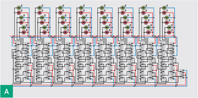
![]() Fig. A: Switches and wires can emulate many operations in digital computing. This circuit adds two 8-bit numbers. Each green LED indicates a 1, while each red LED indicates a 0.
Fig. A: Switches and wires can emulate many operations in digital computing. This circuit adds two 8-bit numbers. Each green LED indicates a 1, while each red LED indicates a 0.

![]() Fig. B: The wiring for the schematic in Figure A.
Fig. B: The wiring for the schematic in Figure A.
Charles Platt
 START
START
Schematics
Figure C shows 3 switches to be controlled by Player 1, and 3 similar switches for Player 2. Each player presses a switch to indicate his choice of rock, paper, or scissors (indicated on the schematic by letters R, P, and S).
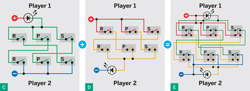
![]() Fig. C: This circuit lights the LED in response to the 3 switch combinations that represent a win for Player 1.
Fig. C: This circuit lights the LED in response to the 3 switch combinations that represent a win for Player 1.
![]() Fig. D: The LED in this circuit lights in response to any of the winning switch combinations for Player 2.
Fig. D: The LED in this circuit lights in response to any of the winning switch combinations for Player 2.
![]() Fig. E: The circuits in Figures C and D are combined using double-pole switches to create a minimal rock-paper-scissors game.
Fig. E: The circuits in Figures C and D are combined using double-pole switches to create a minimal rock-paper-scissors game.
The connections are colored to make them easily distinguishable in subsequent schematics. Think of the colors as being like colored insulation on the wires.
Study the circuit, and you’ll see that when 2 switches sharing a green path are closed, they light Player 1’s LED. The switches are wired in series, so they must both be closed to establish the outcome of the game. But each pair is wired in parallel, so any pair will light the LED.
Each of the switch pairs will win the game for Player 1, while other combinations do nothing. Now check Figure D, which shows the 3 winning switch combinations for Player 2.
We can merge the 2 schematics by using double-pole switches, as in Figure E. One LED or the other will light up to identify the winner. If both players make the same choice, nothing happens. This is a complete emulation of the game, but we can add a lot more details.
To prevent cheating, the players should be unable to see each other’s switches. But when the players have both pressed their switches, their choices should be shown by LEDs. We need 3 LEDs to show which of the 3 switches Player 1 has closed, and 3 LEDs for Player 2. However, these LEDs should not light up until both players have committed themselves. How can this be done?
Figure F shows the simplest circuit. By wiring the 2 groups of LEDs in series, we guarantee that Player 1’s choice won’t become visible until Player 2 also makes a choice, because that’s the only way to complete the circuit. It is absolutely nonstandard practice to wire LEDs in series, but they will work if you use special LEDs containing their own resistors, specified in the parts list.
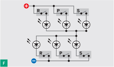
![]() Fig. F: How to wire 6 LEDs to show which switches have been pressed.
Fig. F: How to wire 6 LEDs to show which switches have been pressed.
Figure G shows the player LEDs merged into the main schematic, using 3-pole switches. But wait, there’s more. Figure H shows another enhancement to the game: a noisemaking device which sounds when the game is a tie because both players have made the same choice. Figure I shows this feature added to the main schematic.
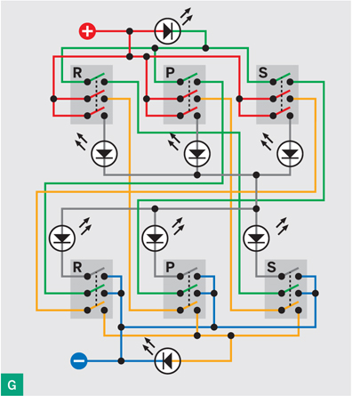
![]() Fig. G: The LED circuit is now embedded in the main schematic.
Fig. G: The LED circuit is now embedded in the main schematic.
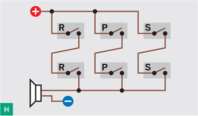
![]() Fig. H: Additional wiring sounds a “tied game” beeper.
Fig. H: Additional wiring sounds a “tied game” beeper.
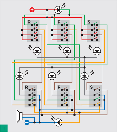
![]() Fig. I: The beeper wiring is added to the main schematic.
Fig. I: The beeper wiring is added to the main schematic.
If you build this circuit using 4-pole pushbutton switches of the type recommended in the parts list, you’ll find they are double-throw switches. In other words, they have contacts that are normally closed, as well as contacts that are normally open. Figures that show the functions of the pins and how the switches can actually be wired together, along with game enhancements (such as a score counter and a way to prevent each player from cheating by pressing more than one switch at a time) can be found at makezine.com/28/electronics. ![]()
![]() Make: Electronics book at the Maker Shed: makezine.com/go/makeelectronics
Make: Electronics book at the Maker Shed: makezine.com/go/makeelectronics
Charles Platt is the author of Make: Electronics, an introductory guide for all ages. A contributing editor of MAKE, he designs and builds medical equipment prototypes in Arizona.