
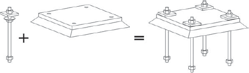
Structural columns, which are different from architectural columns, are what help support almost every building. They are a major part of the skeleton structure that other structural elements like beams and slabs connect to. For this reason, they are probably going to be one of the first or second components that you will model in your project and will be the primary focus in this chapter.
Columns can take on many different shapes and sizes, as well as different construction materials. Depending on the type of material they consist of—wood, steel, precast, concrete—they demand different connection requirements, annotations for location, and documenting of sizes and reinforcing (if any). You should understand the various behaviors each scenario will bring.
Columns are typically defined as a vertical structural member; in today's world, they can become sloped, tapered, skewed, bent, and in some cases spiraled. Yes, you name it, and eventually a column will probably have to take on that form. Buildings are no longer square in footprint and straight-up vertical in height.
Even though columns are a major part of the building process, the basic structural column is simple to model and work with when using Revit Structure. Those that are not so basic in size and shape or vertical in height can be created and placed in a similar method but might not take on all of the functionality of a simple column.
In this chapter you will learn to:
Work with the basic structural column family template
Place structural columns in your project
Attach structural columns to other structural components
Employ the methods of placing slanted columns
Document your model with the Graphical Column Schedule
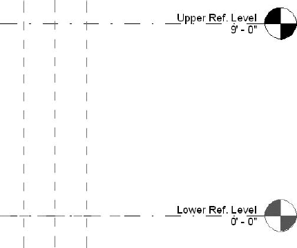
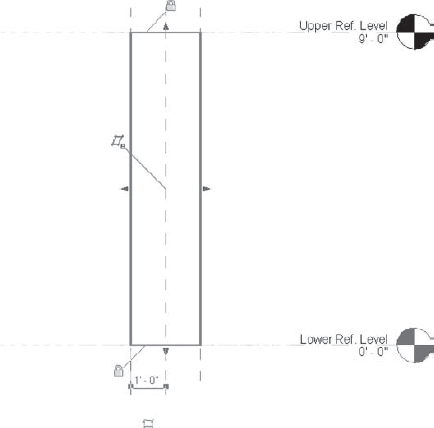
Revit Structure has two column template families to help you create the behavior or intent of the columns you place in your project: column.rft and Structural Column.rft. Both templates have Upper Level and Lower Level constraints, as shown in Figure 4.1, which indicate where the top and bottom of the column should be locked and referenced to. We'll discuss the use of these levels in the section "Adding Structural Columns to Your Project." Because they are each set to a different category, they will present completely different behavior when they are loaded into your project. So when you are working with Revit Structure, make sure that you are using structural columns (Structural Columns category) and not architectural columns (Columns category). There is a dramatic difference in them, such as how they join to other elements as well as their structural properties, which will limit your capabilities if you use the wrong ones.
A third template is called Generic Model.rft. This template does not have the Upper Level parameter, which means you do not have to place it with a Top Level reference. As long as you set the category to Structural Column, it will be available to choose from within the Structural Column list and continue to behave like a column—it just will not be locked to a top level. The reference level in the family will reference a level of your choice in the project. This level can be used for uniquely shaped and placed columns that are specific to your project.
Figure 4.2 shows a unique structural column that was created with the Generic Model template. This column has two ring beams with varying heights throughout the structure. The top ring supports the roof, and the bottom ring supports the ceiling. Round skylights sit at the top of each column. This unique structural column family obviously does not work with Analysis programs, but as you can see, it proves to be valuable from a visualization standpoint as well as for documenting the model.
Getting to know the various column-related categories that are a part of Revit Structure as well as their behavior will allow you to better control how they display in the model and in your documentation. Different templates are available that have certain settings already built into them. You should also understand the various methods and reasons for loading a new column type into your project or duplicating existing types to change their properties.
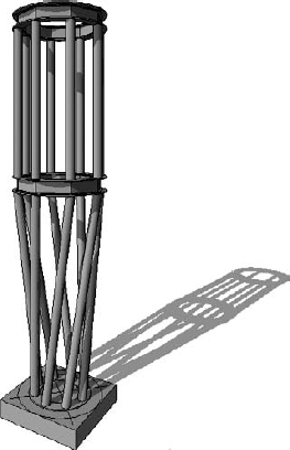
Figure 4.2. A structural cluster column created from a Generic Model template Courtesy of Ericksen Roed & Associates
Architectural columns, which are assigned to the Columns category, are typically used by the architect to create elements such as column surrounds and structural column placeholders. This column type is useful to architects because it can automatically join with wall geometry when it comes into contact with it. This means that architects can easily convey the "column-ness" of what looks like a column without actually placing a structural column. They can focus on the space they want to allow for a structural column but not worry about the engineering-determined size until they have figured it out. Architectural columns can also be used as a design phase – related tool. In schematic design they are wonderful, but for construction documents or quantity takeoffs for walls and drywall, they don't perform as well. Architectural columns are basically intended to stand in for real columns and walls until you know what you want to use. Because of this you probably will find that you will not use these types of columns very much when working on your structure-only projects.
You can place architectural columns by selecting the Home tab
Architectural columns can have the same appearance as structural columns, so from the surface it can be hard to tell which category of column they are set to. Figure 4.4 shows examples of column families that have already been created and are available to use as part of the Revit Structure installation.
Another thing to note about architectural columns is that structural elements do not recognize them—which means that structural elements do not attach themselves to architectural columns, the columns do not have any analytical information or symbolic display, and the columns will not show up in a Graphical Column Schedule. Once you place an architectural column, you cannot easily swap it out with a structural column, so be sure to make users aware of these differences. Trying to swap out the category inside the family after it has already been placed in your project may confuse Revit Structure and create errors when you load the family back into your project.
Something Just Isn't Right
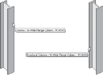
If you are noticing strange behavior with your columns or you just can't see them in some of your views, you might want to verify whether they are architectural or structural columns. Someone may have accidentally placed an architectural column or copied it from a linked model. As you can see in the following graphic, you can easily verify which category the column is set to by hovering your mouse cursor over the column and reading the pop-up notification that displays. The first set of words indicates the category name of the object.
If your columns are not displaying, you might want to check the visibility settings of the view to see if the Columns category is checked to display. By default, Revit Structure will have this category set to not display in some views.
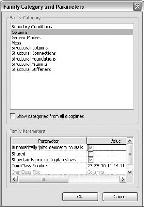
Since the architectural column is meant for nonstructural purposes, its built-in family parameters (shown in Figure 4.5) are limited and therefore much different from what you will see when you toggle to the Structural Columns category. These parameters are built into the Family template, which helps Revit Structure understand and control their behavior depending on the family category they are a part of. You can continue to add your own parameters to build additional intelligence into them.
Structural columns are the columns that you should be using while modeling in your project. Therefore, the remainder of this chapter will explore the placement and behavior of structural columns. Before starting to place columns, you should have a good understanding of their properties and how they behave when placed in your project.
Structural columns are similar to architectural columns in the way that they look, but they automatically take on specific properties depending on their configuration and industry standards. They also have an analytical representation attached to them, which can be exported and used in other analysis design software.
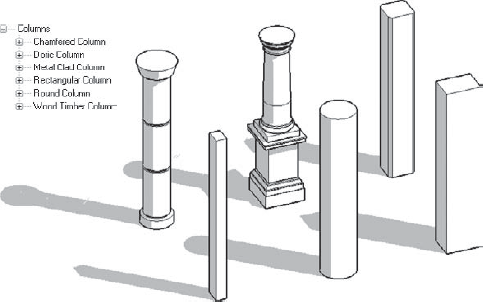
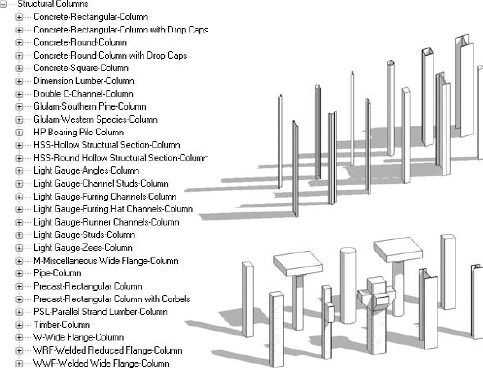
Unlike walls, slabs, and roofs (which are system families), columns are considered a component (external) family. This means that they can be created outside your Revit Structure project as independent RFA (Revit family) files and loaded into your project. As a last resort for modeling unique items that are not repeated throughout the project, you can create structural columns as an in-place family directly inside your project. Since they are a component family, you have the freedom to create just about any shape you want. Figure 4.6 shows examples of structural column families that are part of the stock content provided with the Revit Structure installation. These families go a long way when it comes to modeling, but you will find that for some projects you will have to either modify existing ones slightly or create your own that look totally different.
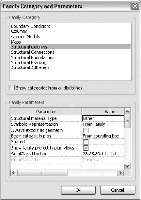
As you can see in Figure 4.7, the Structural Columns category has a few built-in parameters that allow it to behave differently depending on these parameters' settings inside the family. Setting the Structural Material Type parameter will let you add or remove additional parameters that pertain specifically to the material being used. In some cases, you might find that you need to have families containing the same geometry, but these options are set differently, so the geometry in each family displays a certain way when placed in your project.
When creating your own structural column, make sure that you set Structural Material Type inside the family to the proper material that it is meant to represent. You can select from five different material types: Other, Steel, Concrete, Precast Concrete, and Wood. This material property is different from the material that you assign to the family to give it surface and cut patterns and rendering appearance. This is what tells Revit Structure how the family behaves as it interacts with other structural elements and as it displays in certain views. For instance, a concrete beam that frames into a concrete column behaves differently than a steel beam that frames into a steel column or a steel beam that frames into a concrete column. Figure 4.8 shows the automatic behavior that is derived from this setting.
The Structural Material Type parameter helps determine whether the two elements should join their materials together with a construction joint or place the steel beam with a setback dimension. Each material behaves differently based on common industry conditions when it interacts with different materials. The Graphical Column Schedule also uses this setting, which allows you to schedule only columns of a certain material type. This makes this option one of the most important and the first one you should set when creating your column families.
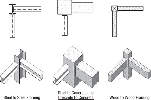
Figure 4.8. The Structural Material Type setting within a structural column family helps determine how other structural elements attach to the column.
No, It Really Is Not the Right Material
When you are working with concrete, you might want to join two separate elements together to remove a construction joint. Let's say you need to join a concrete column to a concrete slab, and part of the column must be poured with the slab. To join these monolithically, both elements need to have the same material assigned to them. You keep checking the materials, and both the column and the slab have the same concrete material assigned to them. You have toggled among all three different Detail Level settings, and you still cannot get the construction joint to be removed. One last thing to try would be to edit the family and check the Structural Material Type setting referenced in the Family Properties panel
This setting affects the family only when your views are set to a coarse detail level. If your column family is going to be a steel or wood material, you will probably want to have this option set to From Project Settings. That way, Revit Structure will automatically place symbolic lines to represent the column in a plan, section, or 3D view when set to a coarse detail level. You can control the display of this symbolic line by the subcategory Stick Symbols under the Structural Columns category. It also controls the symbols that are displayed for the Top and Bottom connection types that are set in the Structural Settings dialog box for the project and an instance parameter of a column. You can control the display of these symbols through the Connection Symbols category under the Annotation Categories tab in the Object Styles dialog box. For most companies, this will be the industry standard for showing steel or wood at reduced scales, which would also be shown in Revit Structure's coarse detail level view.
When using concrete or precast concrete, you would typically show the true double-line representation of the shape in all detail levels. For this reason, set the Symbolic Representation option for these families to By Family. This tells Revit Structure to not automatically place symbolic line work and symbols for those families.
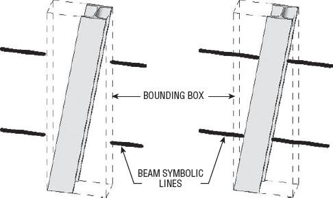
This is another setting that affects the family only when your views are set to a coarse detail level. Beam Cutback in Plan refers to the stick symbol symbolic line, which Revit Structure automatically generates for a beam family when its Symbolic Representation option is set to From Project Settings. If set to From Bounding Box, the symbolic line will be cut back from the bounding box of the column; if set to From Geometry, the symbolic line will be cut back from the geometry of the column. You are probably wondering, "What is a bounding box?" A bounding box is an invisible box that Revit Structure places to the extents of the geometry inside the family. This concept is best shown with a sloped column, as in Figure 4.9. Revit Structure uses this box to help it make decisions during its automated process. In the scenario of a beam framing into a column, the Symbolic Cutback Distance setting in the Structural Settings dialog box will start its offset dimension from the bounding box or the geometry of the column, depending on the settings in the Column family.
Display in Hidden Views
When Structural Material Type is set to Concrete or Precast Concrete, this parameter becomes available to help control the visibility of hidden lines that should or should not display in your concrete column families. There are three settings for this parameter: Edges Hidden by Column Itself, Edges Hidden by Other Members, and All Edges. Figure 4.10 shows the various displays that Revit Structure will produce depending on what your family is set to.
In some cases, you may need an exact duplicate of your family with a different family name. The only difference between the two families may be the Display in Hidden Views setting. Sometimes you may have to create duplicate families with different settings so your column with special conditions displays properly once it's in your project.
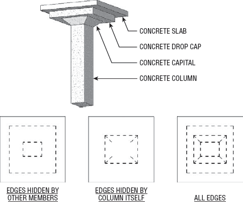
Figure 4.10. Setting the Display in Hidden Views option in the Structural Column family produces various plan displays.
Since structural column families are component families, you will need to import them into your project in order to use them. Once the families are in your project, you will be able to duplicate them to create different sizes. Some structural column families will be created with a type catalog file that is part of the family. This type catalog file allows you to define a list of preset types that let you lock in the settings for each type and display them in a list to choose from when importing. You can find additional information on the use of type catalogs by searching the Help index in Revit Structure.
To load a structural column family or any other component family, choose the Insert tab
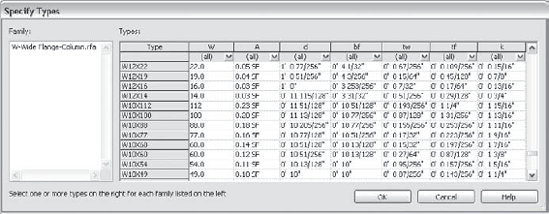
Type catalogs are typically used when the structural shape properties are pretty much static for their type. The properties of steel, light-gauge steel, and wood shapes are usually pulled right from a product catalog or are industry standards. Structural elements that are concrete or precast concrete can come in just about any shape you could imagine, so putting them in a type catalog would be exhaustive. However, if a family's types are used repeatedly throughout other projects, your exhaustive efforts will pay off.
Most families such as the wide flange member or a precast L-beam maintain their basic form; just the actual dimensions that define their size or related information change. A type catalog can make it easier for you to create a long list of sizes rather than having to create them in the Family Types dialog box each time you need a new size. It also means that you don't have to load all the types of a family when you really need to use only a couple of them. A quick look at the wide-flange family shows lots of types, but you use only a small fraction of them in a project. Certain families you create may warrant using a type catalog; you will need to decide when the right time is to use one for your families.
When working with families that are using type catalogs, you should load in new shapes from the catalog rather than duplicate them. You load new types in the same way you load the family for the first time. Use the Duplicate method for families that do not use type catalogs.
One method to duplicate a Structural Column, is to perform the following steps:
Select a column that you want to duplicate.
Click the Duplicate button in the Type Properties dialog box.
Give the duplicated column a new name.
While still in the Type Properties dialog box, make changes to all parameters that differ from the other types.
Click OK in all subsequent dialog boxes.
Another method to duplicate a Structural Column, is to perform the following steps. (This method allows you to create new types without touching already modeled elements.)
Select a column type from the Project Browser in the Structural Columns category.
With the column type selected, right-click and select Duplicate.
Give the duplicated column a new name.
Right-click on the new column type and select Properties.
While in the Type Properties dialog box, make changes to all parameters that differ from the other types.
Click OK in all subsequent dialog boxes.
Exercise: Creating a Simple Structural Column Family
In this exercise, you'll use a simple structural concrete column, one that is already created for you in the Revit Structure installation. Going through the steps will help you grasp the idea and help you create structural columns of much greater complexity.
Choose the Application menu

Browse to
Imperial TemplatesStructural Column.rftand select it to open it.From the Create tab on the Ribbon choose the Family Properties panel
Set the Structural Material Type option to Concrete. Click OK to close the dialog box.
While in the plan view, choose the Create tab
Use the Align command on the toolbar to align and lock the sketch lines to the reference planes, as shown here:
Note that placing the initial sketch lines away from the reference planes and then aligning and locking to them afterward ensures that your sketch lines are properly locked to the reference planes.
Click Finish Extrusion from the Extrusion panel on the Ribbon.
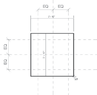
Place dimensions between the reference planes for both the width and height of the column.
Create a Label parameter, as shown in the following graphic, so the extrusion will flex inside your project. You can easily do this by selecting the dimension(s) and then selecting Add a Parameter from the Label box on the Options bar.
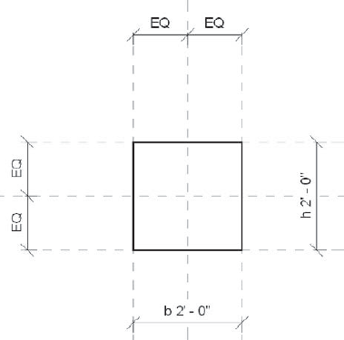
In the Parameter Properties dialog box, fill out the appropriate information by giving each parameter a name (here we use b and h, which is consistent with Revit Structure's references to width and height in the other structural column families) and group them under Dimensions. Make them a Type parameter and click OK.
Note that when using this method the Type of Parameter value has already been set to Length. This is because a Length parameter is the only type that can be assigned to this type of dimension.
Open the Front Elevation view from the Project Browser.
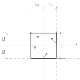
Select the solid form, drag the top grip (triangle) up until the Upper Ref. Level is highlighted, release the mouse button, and click the padlock that appears to lock the relationship between the top of the solid and the level.
With the solid still selected, drag the bottom grip (triangle) up and then back down until the Lower Ref. Level is highlighted, and release the mouse button. Click the padlock that appears to lock the relationship between the bottom of the solid and the level.
Select the extrusion and open its Element Properties dialog box.
In the Element Properties dialog box, select the little rectangular button next to the Material parameter, in the = (equals) column.
In the Associate Family Parameter dialog box, click Add Parameter.
Name the parameter Material, make it an Instance parameter, and group it under Material and Finishes.
Click OK to return to the Element Properties dialog box.
Notice that the little rectangular button next to the Material parameter now has an equals sign in it. Steps 15, 16, and 17 just added a parameter to your family and hardwired it to the extrusion, so when you place the parameter in your project, you are able to assign different materials to each instance of a column that you place. Click OK to close the Element Properties dialog box.
Perform a few safety checks by changing the Dimensions values in the Types dialog box located in the Family Properties panel of the Ribbon to make sure that your new family flexes properly. Also, choose the Lower Ref. Level and move it up or down, and do the same with the Upper Ref. Level to verify that the top and bottom of the column are constrained properly to the levels.
If you have not done so already, make sure to save the family in case you would like to use it later on.
After learning about the various column family libraries and what makes them tick, you are ready to move on to placing columns in your project. You can use the Structural Columns-STL.rvt file for this section of the chapter. Before placing structural columns, you should have levels and a pretty good portion of your grids generated. The top and bottom of any columns will need to refer to levels that are already generated in the model. If you place columns on grids, you can set them to stay attached to the grids. You can do so by making sure that the Moves with Grids option on the Options bar is checked when a column is selected or that the Moves with Grids parameter is checked in the column's Instance properties. That way, when a grid moves, the column moves with it. The grids also allow modeled columns to display in a Graphical Column Schedule.
The natural tendency when starting a project is to model your columns full height from the top of the foundation to the roof. This makes perfectly good sense in a single-story structure. But you have to stop and ask yourself, "What concrete column is poured in a 100-foot lift?" or "Who erects a 100-foot-long steel column?" The preferred method is to place columns as the building will be built. Note that the Split tool doesn't work on columns, so think about how you are going to get to the finish line to achieve the "model as it's built" concept before you start.
If you are modeling a concrete post-tensioned or flat plate structure and the columns go floor-to-floor, you should model the columns floor-to-floor. A good rule is to stop the columns at the construction joint—which will most likely be the top of the slab for the bottom of the column and the bottom of the next slab above or below the beam for the top of the column. Typically, concrete structures are erected floor-by-floor, so the concrete columns would be placed level-to-level in Revit Structure just as they will be built out in the field.
If you are modeling a steel structure, the columns are more than likely going to be erected to a certain height before they will need to be spliced. This might be necessary to meet Occupational Safety & Health Administration (OSHA) requirements or because of a change in column size. A steel column usually projects above a specific level before it splices, stopping just below a level at a roof or termination of column condition. Regardless of the scenario, you should be modeling columns as they will be built.
Not only does modeling structural columns as they are constructed give you a more accurate BIM model, but when it comes to creating sections and Graphical Column Schedules and performing quantity take-offs, you will spend less time developing your sections, create a useful schedule, and have a much more accurate representation of material amounts.
The biggest part of mastering the placement of structural columns in your project is learning the ways that you can place them and knowing the best times to use those particular methods. Thinking ahead in the modeling process and attaching structural columns to other elements (so they adjust to changes in the model) will help keep element relationships consistent and their parametric behavior as you intended.
To begin placing your structural columns, select the Structural Column tool from the Home tab
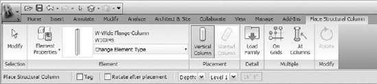
Figure 4.12. The Options bar and contextual tab give you several options for placing a structural column.
The following is an overview of what's available to you for placing structural columns into your project:
Ribbon panels
Before placing a column, you can edit the Element properties of the currently selected column or duplicate it to make a new column type.
From the Type Selector pull-down in the Element panel, select the type of structural column you want to place.
In the Placement panel you can choose to place a vertical column or a slanted column. The Slanted Column tool is not available in a plan view.
You can load a new family on the fly by choosing the Load Family tool from the Detail panel.
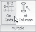
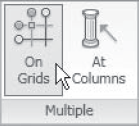
Two additional placement options in the Multiple panel are On Grids and At Columns. These are both explained further in "Using the On Grids Option" and "Using the At Columns Option."
Options bar
If you want the columns to be tagged in the current view directly after placement, select the Tag check box.
Selecting the Rotate after Placement option automatically opens the Rotate command after placement, with the insertion point that is defined within the family by two reference planes serving as the center of rotation.
In the Height/Depth area, you can choose to place the column with a depth (going down) or with a height (going up) with a reference to the current level you are placing it in.
To the right of the Height/Depth area is the Constraint list, where you can set the constraint of the top or bottom of the column or set it to be unconnected.
If you're using an unconnected height, you can give a depth or height of the column from your current level.
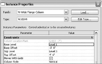
After you place the columns, take a look at the properties of a few of them. You will find that their Instance parameters will vary depending on the structural material type assigned to them in their family as well as how they are placed in the model. Figure 4.13 shows that a steel column will have additional Graphics parameters for the display of symbolic symbols and concrete columns will have additional Structural parameters for the concrete cover.
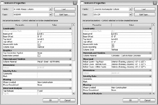
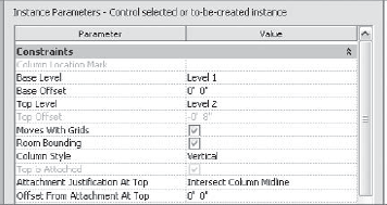
Every structural column will have a base and a top level that the bottom and the top of the column refer to. From each of those references, you can specify a top or bottom offset from the specified reference level. If you have an interior column sitting on a footing that is 8″ below the Level 1 slab on a grade, the Base Level option of the column would be set to Level 1 with a Base Offset dimension of −0′-8″. The same column that goes up and splices 4′-6″above Level 3 would have its Top Level option set to Level 3 with a Top Offset setting of 4′-6″.
You will also see a Column Style parameter. This parameter will come into play in a later section called "Adding Slanted Columns to Your Project." This parameter sets the behavior of the column in your project. Is it vertical or is it a slanted column?
When you place structural columns in Revit Structure, several tools are available that allow you to place them quickly as well as ensure that they are placed properly. Using the Single Pick option will place single columns one-by-one and also control the rotation of each specific placement. Using the On Grids or At Columns placement options allows you to place several columns at once while using other elements for their placement location.
The Single Pick option is the initial state that Revit Structure starts in after you select one of the structural column placement tools. This allows you to place columns one at a time and easily adjust settings between each placement.
To use the Single Pick option, follow these steps:
Columns will be placed using the Depth option by default, so activate an upper-level plan view or change the option for Depth/Height if you prefer a lower-level plan view.
On the Home tab
Select the type of column you want to place.
Observe the Options bar and make any necessary settings. Click the Element Properties button, and set the Top Level and Base Level values as well as any offsets that are required.
Start placing columns one-by-one and watch them snap to the intersection of gridlines.
You can rotate columns while placing them by pressing the spacebar. Each tap of the spacebar rotates the column 90 degrees. If on gridlines, the column will snap perpendicular to them and use an angle degree that's half the grid intersection angle.
You can tag each column as you place it by checking or unchecking the Tag check box in the Options bar.
This method is useful for placing columns that are not on grids or that require a more specific location or rotation. Even after the columns are placed, you can use the spacebar to rotate them by selecting one or more columns and pressing the spacebar.
If you use this method for grid intersection placement, take care to ensure that you are placing the column at the correct intersection point rather than at another unexpected intersection point. Keep an eye on the status bar located in the lower-left area of your Revit Structure session dialog box to verify where the column is being placed. Setting the Visibility properties of a view to show only grids and columns may help you select the correct intersection point.
The On Grids option allows you to select groups of grids for placement. Revit Structure will place a column on each intersection for all the grids that you select. This can be a quick method for getting columns into your project. Even if there is not supposed to be a column on a particular grid intersection, it can still be more efficient to place a column on it and remove it afterward.
Ask yourself which way you can do it faster. Should you place 50 columns by using the Single Pick option, or should you place 55 columns with the On Grids option and erase 5 of them afterward? Figure 4.14 shows that you can place 30 columns onto your gridlines in a matter of seconds.
For grid intersection placement, perform these steps:
Columns will be placed using the Depth option by default, so activate an upper-level plan view or change the option for Depth/Height if you prefer a lower-level plan view.
On the Home tab
Select the type of column you want to place.
Observe the Options bar and make any necessary adjustments.
Select the On Grids Placement option from the Multiple panel.
While in this mode, the Options bar will refresh to display the option Tag the Column(s) after Placement. From the Ribbon, cancel out of the tool or choose Finish Selection to accept your grid selection. Note that you have to choose the option to tag before selecting grids. Otherwise, you can't check the box; it will be unavailable to select.
Select all grids with a right-to-left crossing window. You should see columns display at the center of all selected grid intersections.
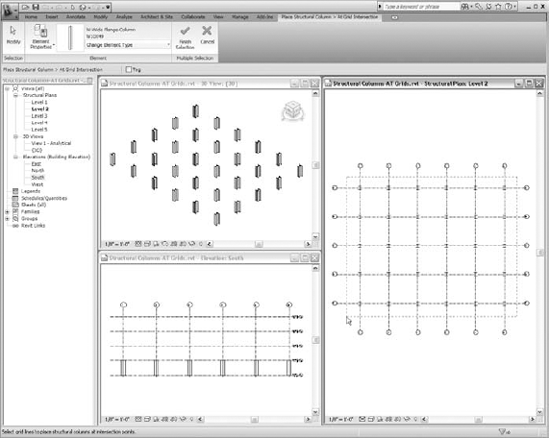
Figure 4.14. Placing columns with the On Grids option will quickly and accurately place them onto gridlines.
Select grids by clicking the gridlines and holding down the Ctrl key to add to your selection or by holding down the Shift key to subtract from your selection. You should see columns appear and disappear at the center of grid intersections as you add and subtract grids from your selection.
Once you've selected all required grids, be sure to click the Finish Selection button from the Ribbon to accept your column placement. Any other action will remove your placements.
You can now delete any unwanted columns that are on grid intersections and do any fine-tuning of their rotation.
Using this method will help ensure that all columns are accurately placed at the exact intersections of the grids. This will also ensure that the columns will properly be attached to the grids so that when the grids move, the columns will move with them. When columns are properly placed at grid intersections, they will continue to display in the Graphical Column Schedule (which we discuss later in this chapter).
If you have architectural columns modeled in your project, you can use them to place your structural columns. As shown in Figure 4.15, Revit Structure will place a structural column at the center of all architectural columns that you select. If this method of placement fits in with your modeling workflow, this can be a quick method of getting columns into your project.
For At Columns placement (which requires an architectural column to place a structural column), perform the following steps:
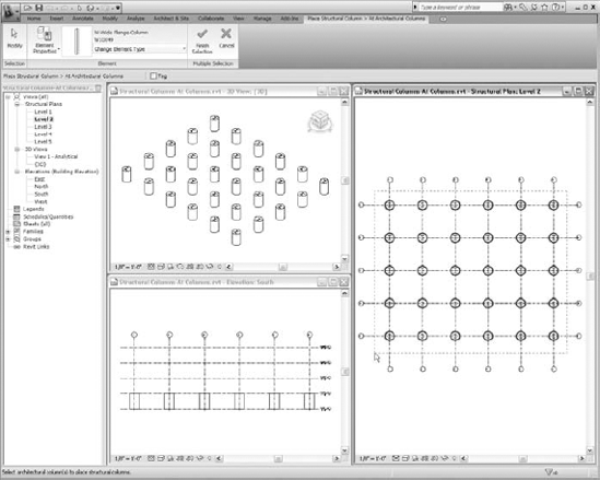
Figure 4.15. When you use the At Columns option, Revit Structure will place a structural column at the center of each architectural column that you select.
Columns will be placed using the Depth option by default, so activate an upper-level plan view.
On the Home tab
Select the type of column you want to place.
Observe the Options bar and make any necessary adjustments.
Select the At Columns Placement option from the Multiple panel.
While in this mode, the Options bar will refresh to display the option Tag the Column(s) after Placement. From the Ribbon, you can cancel out of the tool or choose Finish Selection to accept your architectural column selection.
Select all architectural columns with a right-to-left crossing window. You should see structural columns display at the center of all selected architectural columns.
Select architectural columns by clicking them and holding down the Ctrl key to add to your selection or by holding down the Shift key to subtract from your selection. You should see structural columns appear and disappear at the center of each architectural column as you add and subtract them from your selection.
Once all required architectural columns are selected, be sure to click the Finish Selection button from the Ribbon to accept your column placement. Any other action will remove your placements.
If you are using this method to place your columns and the architectural columns that you're selecting are from an outside client, make sure that architecturally the columns are accurately placed. Usually an architectural column will be in the form of a column surround, so when you place the structural column you place it within the surround. Communicating the behavior of the columns to those who created them will help achieve an accurate placement.
Some companies may use the structural linked model to display structural columns in their model, so this can be an excellent way to collaborate and keep your documents coordinated.
Once you have columns placed in your project for one of your levels, another time-saver you can take advantage of is to copy them to other levels as needed. Each project will be a little different, so you will have to use your judgment on which tools and methods are best to use.
The basic procedure goes like this:
Select the column(s) that will be copied to other levels.
Switching to a 3D view to perform your selection and then using the Filter Selection tool to select only the columns can speed up the selection process. The 3D view allows you to orient to an elevation view that lets you select through the model with no clipping plane.
After element(s) are selected, choose Clipboard panel
If the element(s) are still selected, choose Clipboard panel
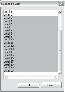
- Select Levels/Select Levels by Name
Choosing this option allows you to paste the element(s) you have copied by picking from a list of levels that are in your project to paste the element(s) into. Using the Ctrl and Shift keys on the keyboard while selecting the levels from the list allows you to include multiple levels in your selection.
- Select Views
Choosing this option allows you to paste the element(s) you have copied by picking from a list of views. It is typically used for pasting annotation and detail items into view(s). If element(s) that will be pasted do not meet the proper criteria for any views in the project, this option will be unavailable. This is common for modeled geometry. Elements such as detail lines, annotations, dimensions, and filled regions will typically display a list of views that the element(s) can be pasted into. Using the Ctrl and Shift keys on the keyboard while selecting the views from the list allows you to choose multiple views in the list.
- Current View
Choosing this option allows you to paste the element(s) you have copied into the active view. Those element(s) that are being pasted will be hosted or referenced to the level associated with your current view if they are level, hosted, or work plane based. This option may be unavailable if the proper criteria of the current view are not met for pasting the element(s), such as attempting to paste a column into a section view.
- Same Place
Choosing this option allows you to paste the element(s) you have copied to the exact same place that they were copied from regardless of the view you are in. It will also display a warning that reads: "There are identical instances in the same place. This will result in double counting in schedules." This is just telling you that you now have duplicate elements on top of each other and what can happen because of it.
Pasting Columns in the Same Place
Since the Split tool does not work on columns, you can paste in the same place when you have modeled a structural column the full height of the building and need to split it into additional elements to follow the model-as-it-is-built approach. After the structural column is pasted in the same place, you can adjust the base and top constraints until there is no longer duplication of the elements.
A short example would be as follows: Column A runs from Level 1 to Level 3. Copy column A to the clipboard and use Paste Aligned
In a floor (slab) example you could split a floor into separate floors by doing the same thing. Select one floor and modify its sketch lines. Select the other floor and modify its sketch lines. You now have two floors without having to resketch the entire floor shape.
- Pick Level/Pick Level Graphics
Choosing this allows you to paste the element(s) you have copied by picking the geometry of a level. The cursor will display the usual arrow with an additional level head symbol indicating that you must select a level. If you are not in a view where levels exist, you will have to switch to one that does have them.
After you select a Paste Aligned option, the columns will be placed into your model depending on which method you select.
While the columns are still selected, right-click and choose Properties from the shortcut menu.
Make any parameter adjustments that are needed for the final location of your columns.
Using Paste Aligned
Exercise: Placing Structural Columns for a Steel Structure
For this exercise, you can use the Structural Columns-STL.rvt file. You will go through the steps of placing columns into your project first by placing the first lift. You'll then use the Copy to Clipboard method to place the upper levels. Columns will span two supported levels before requiring a splice connection.
Open the
Structural Columns-STL.rvtmodel.Open the Level 3 view (if necessary). Note that the first lift of columns will go from Level 1 to Level 3.
Select the Home tab on the Ribbon, and choose the Column drop-down
Select W10X49 from the Type Selector pull-down.
Set the column constraint option to Depth and the bottom constraint to Level 1.

For the placement option, choose On Grids.
Select all grids from upper right to lower left. Temporary columns will display.
Click Finish Selection from the Ribbon to make your selection permanent.
Delete the columns on grids A-4, A-5, A-6, B-4, B-5, and B-6.
Open a 3D view, and orient the view so that you're looking south by selecting the S on the ViewCube, shown here:
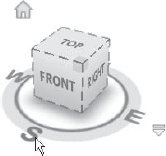
Working with the controls on the ViewCube is the quickest way to maneuver the view to preset directions. However, you can also select the drop-down that appears adjacent to the ViewCube. This drop-down displays additional options for choosing the orientation of the current 3D view.
When you select columns in the following steps, it appears that you are selecting only six columns when creating a right-to-left crossing window. Since a 3D view does not have a clipping plane, you actually are selecting all columns; 24 should be listed on the status bar next to the Filter icon, bottom-right corner.
Select all columns that you previously placed with a right-to-left crossing window, right-click, and select Element Properties to access the columns' Instance properties.
Change the Top Offset value to 4′-6″and close the Instance Properties dialog box.
While columns are still selected, choose Copy from the Clipboard panel on the Ribbon.
While columns are still selected (important because you'll have to use a different Ribbon tab if they are not still selected), choose the Paste Aligned drop-down
The levels were selected for the tops of the columns because Revit Structure will place them using the Depth option when they are pasted. If columns are not still selected, you will have to choose the Paste Aligned drop-down from the Modify tab
Select the second lift of columns that go from Level 3 to Level 5 with a right-to-left crossing window (as shown here), right-click, and select Element Properties to access the columns' Instance properties.
Change the Base Offset value to 4′-6″ and close the Instance Properties dialog box.
Select the third lift of columns that go from Level 5 to Level 7 with a right-to-left crossing window, right-click, and select Element Properties to access the columns' Instance properties.
Change the Base Offset value to 4′-6″ and the Top Offset value to −0′-5″ (the depth of the slab), and close the Instance Properties dialog box.
Check that all columns are placed correctly.
Using a top offset for the column that matches the thickness of the slab will not create a relationship between the column and the slab. If the slab changes thickness, you will have to change the Top Offset value accordingly. Another option is to attach the columns to the bottom of the slab. With this method, the top of the column will automatically adjust as the slab thickness changes. To view a completed model of this exercise, see the Structural Columns-STL_Complete.rvt file.
Like walls, the top and bottom of columns can be attached to other structural elements such as floors, roofs, foundations, and structural framing members to help maintain their relationship. They can also be attached to reference planes and reference levels. The Ribbon will switch to display Attach and Detach buttons on a contextual tab, as shown in Figure 4.17, when you select a structural column. When you click the Attach button, the Options bar will display settings for the type of attachment you want to make.
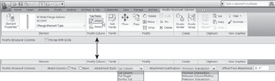
Reading from left to right, the Options bar in Figure 4.17 allows you to do the following:
Select Top or Base to define which end to attach the column to.
Select the attachment style type.
Select the attachment justification type.
Define any offset from the attachment that may be required.
To attach the top of a structural column to a slab, follow these steps:
Select the column(s) that will be attached.
In the Modify Column panel of the Ribbon, click the Attach button.
Select Top on the Options bar.
Set the style and justification methods on the Options bar.
Select the slab that you will be attaching to.
To attach the bottom of a structural column to the top of a beam, follow these steps:
Select the column(s) that will be attached.
In the Modify Column panel of the Ribbon, click the Attach button.
Select Base on the Options bar.
Set the style and justification methods.
Select the beam that you will be attaching to.
The style and justifications will react differently depending on the type of element and the material that you are attaching to. Concrete-to-concrete attachments will result in an automatic join in which neither the column nor the target will be cut. A steel column can cut to a steel beam, but a concrete column cannot. We encourage you to spend a few minutes playing around with the different style and justification types to see how they react with various material types and elements. Knowing these limits will help you put constraints in your model that will save you time further into your project. Figure 4.18 shows examples of various style and justification combinations.
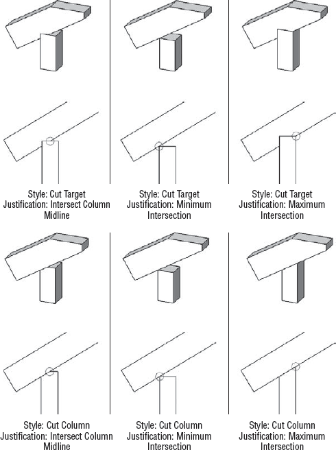
Figure 4.18. Setting the proper attachment style and justification can eliminate tedious detail cleanup.
Exercise: Place Structural Columns for a Concrete Structure
For this exercise you can use the Structural Columns-CONC.rvt file. You will go through the steps of placing columns into your project by placing the first lift and then using the Copy to Clipboard method to place the upper levels. Individual columns will span between each supported level and will be attached to the bottom of the concrete slab.
Place Columns Using the On Grids option
Open the Level 1 view.
Note: The first lift of columns will go from Level 1 to Level 2.
Select the Home tab on the Ribbon and choose the Column drop-down
Select Concrete-Square-Column: 18 × 18 from the Type Selector pull-down.
Set the column constraint option to Height and the top constraint to Level 2.

For the placement option, choose On Grids.
Select all grids, from upper right to lower left. Temporary columns will display.
Alternatively you could create two separate crossing window selections by pressing the Alt key from the keyboard to add the second window selection to your selection. This could eliminate the steps for deleting the columns because you are selecting only those intersections that require columns. There is always more than one way to accomplish a task.
Click Finish Selection from the Ribbon to make your selection permanent.
Delete the columns on grids A-4, A-5, A-6, B-4, B-5, and B-6.
Copy and Paste Columns to Another Level
Display a 3D view.
Select all columns with a crossing window. If more than just the columns are selected, use the Filter Selection tool on the Options bar to select only the columns.
Using the Filter Selection tool will allow you to include only the elements in your window selection that are in the category that you choose to select in the Filter Selection dialog box.
Click Attach from the Modify Column panel of the Ribbon.
On the Options bar shown here, attach the column at the top with a style of Do Not Cut and a justification of Intersect Column Midline.

Select the bottom of the Level 2 slab.
While the columns are still selected, right-click and select Element Properties.
Check the parameters for Top Is Attached and Attachment Justification At Top against those shown here, and close the Element Properties dialog box.
Select all columns, if they aren't still selected.
Choose Copy from the Clipboard panel on the Ribbon.
Choose the Paste Aligned drop-down
If the floor-to-floor heights are the same as the columns you are copying from, then the columns will be placed properly. If not, the columns will be placed with incorrect top or base offset values. Revit Structure will not automatically increase or decrease the height of the column to align with the new levels the column is being associated to.
For example, if the original columns referenced to Level 2 and Level 3 with a height between them of 10′-0″ were pasted to Level 5 and Level 6 with a height between them of 11′-6″, the pasted columns would be referenced to Level 5 and Level 6 with a Base Offset value of 1′-6″. You would see a gap between the slab and the bottom of the column. These columns would then need to have their Base Offset value reset to 0′-0″. Revit maintains the column height and a relationship with the level above and below, but to do so it must adjust the top or bottom offset parameters relative to the levels in order to maintain the same column height.
Verify that all columns are placed correctly.
The columns that originally had their top attached to Level 2 maintained their top attachment to each level that they were copied to. If any of the slabs change thickness or location, the top of the column will automatically stay attached to the bottom of the slab and update the Top Offset value accordingly. To view a completed model of this exercise, open the
Structural Columns-CONC_Complete.rvtfile.
Revit Structure is capable of dealing with most of the requirements of how a structural column must perform. The tools provided to place structural columns into your project as well as help maintain their behavior with other elements work in sync with how you need to work with them when you are modeling. Placing a slanted column is one of those examples where Revit Structure offers tools specifically for modeling elements that are more specific to how they perform. Yes, placing a slanted column in many ways is similar to placing a vertical column; however, how it behaves and adapts to changes in the model can be quite different.
Adding slanted columns into your project is new to this version and thus is much easier to achieve than it was in the past. Slanted columns will behave and react to other framing members the same as vertical columns do. As usual, the Help documentation that comes with Revit Structure is another resource that you should use to further your knowledge of working with slanted columns in your project.
Slanted columns use the same structural column families and tools that you use for placing a vertical column. They have the same properties along with a few added ones that are specific to their slanted nature that control how they behave when changes occur. You can create slanted columns by changing the properties of an existing vertical column or by creating a new one using the Slanted Column tool. To begin the placement of a slanted column, choose the Structural Column tool from the Home tab
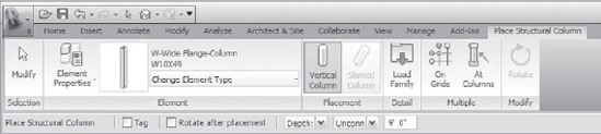
Figure 4.19. The Place Structural Column contextual tab while in a plan view (Slanted Column tool is grayed out)
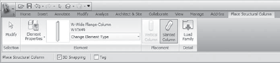
Figure 4.20. The Place Structural Column contextual tab while in a section or elevation view (Vertical Column tool is grayed out)
Within this contextual tab you will see the Slanted Column tool. You will also see the same Type Selector that is used for placing vertical columns as well as the Load Family tool for loading new structural column families. As we said before, slanted columns use the same families as vertical columns; it is their method of placement that is different. Depending on the view you are in while placing them, you will find different options available on the Options bar.
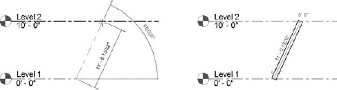
Selecting the Slanted Column tool while in a section or elevation view requires only a few settings from the Option bar, as shown in Figure 4.20, such as choosing 3D Snapping and whether you want it to be tagged. Placing the column is a two-click process. Each of your pick points represents the top or base of the column depending on which point is higher. The endpoint at the higher elevation is the top, and the lower elevation is the base.
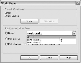
Prior to picking your points, you will also want to set the work plane that the column is to be placed on, or it will be assigned to an unassociated plane that will not be your expected location. If you are in a section or elevation view, you will need to tell Revit Structure which plane to place the column on. In most cases this will be a grid, so your view should be such that it is looking parallel to the grid you will be placing it on. To set the work plane choose the Home tab
Once the work plane is set, you are ready to place the column. Figure 4.22 shows before and after placing a slanted column in a section or elevation view. This method is rather simple and similar to placing them in a 3D view.
Placing slanted columns in a 3D view is similar to the method we just discussed in the previous section for placing them in a section or elevation view. There is no need to specify a work plane because you will be making your top and base point selections by choose the 3D points of elements already placed into the model. Using a 3D view allows you to visualize how the slanted column is going to appear in your model as well as provides the ability to snap to the 3D points on other elements. In a scenario where the top and base of the slanted column may not share the same work plane, placing them in a 3D view is much easier. The process for starting the tool is the same (choose the Home tab
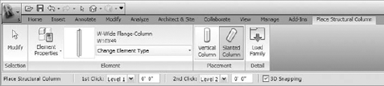
Figure 4.23. Several different options are available on the Options bar when placing slanted columns in 3D view.
The tools for placing slanted columns into your project are easy to work with. Understanding the properties that control vertical and slanted columns will aid in your ability to work with them. The Column Style parameter, which Revit Structure uses to determine these properties, can be used to convert a vertical column into a slanted column without having to replace it.
Columns that are slanted automatically take on several additional parameters that are not available when a column is defined as vertical. These parameters vary depending on how the columns are placed and how they are positioned in the model. The major parameter that controls these properties is the Column Style parameter, shown in Figure 4.24. You have three options to choose from: Vertical, Slanted - Angle Driven, and Slanted - End Point Driven.
Figure 4.24. Setting the column style from the Instance Properties dialog box of a structural column
This is where you can change a vertical column to take on properties of a slanted column, which also enables type-specific modification tools. In some cases you may find that not all of the styles may be available. This is because some styles are not available when certain relationships are detected. For instance, slanted columns attached or joined at their top and base default to the Slanted - End Point Driven column style. The Slanted - Angle Driven column style is restricted to columns without joins or only a single join at their top or base. Changing the relationship so it meets these requirements allows the column style to become available for selection. You can find much more information regarding these joins and the behavior of the relationships between columns and other elements by going to the Slanted Structural Column Attachments and Joins section in Revit Structure's Help documentation.
Angle or Endpoint Driven? What's the Difference?
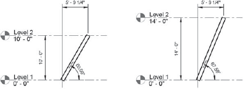
Two styles of columns are available for determining a slanted column. Their difference is in how they lock the geometry of the column's top and base endpoints, which defines the slant (slope) of the column. When the elevation of one of these points changes, how should the change affect the column's location?
Slanted - Angle Driven
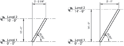
If Column Style is set to Slanted - Angle Driven, it will maintain the angle of the column as the top or base endpoints are adjusted in elevation. The following image shows how a Slanted - Angle Driven column behaves when Level 2 is adjusted from 10′-0″ to 14′-0″; the 60-degree slope is held and the base-to-top horizontal offset is revised. Given its name, you might think that you need to define the angle, but don't be fooled. Revit Structure simply focuses on maintaining the angle defined by the original position of the column when its top or base constraints are altered, whatever that angle may be.
Slanted - End Point Driven
If Column Style is set to Slanted - End Point Driven, it will maintain the horizontal offset of the base and top endpoints of the column as the top or base endpoints are adjusted in elevation. The following image shows how a Slanted - End Point Driven column behaves when Level 2 is adjusted from 10′-0″ to 14′-0″; the 60-degree slope is altered and the base-to-top horizontal offset is held.
Column that are set to a slanted column style inherit additional parameters such as Move Top With Grids and Move Base With Grids, as shown in Figure 4.25. These parameters allow you to set the constraints of the top or base endpoints of the slanted columns to a grid. If the grid moves, the default is to move the top and base of the column with it.
As these columns become attached to other elements such as structural floors, roofs, foundation slabs, and reference planes or joined to other slanted columns, beams, and walls, additional parameters populate the columns' properties. Figure 4.26 shows the properties of a slanted column that is attached and joined to other framing members at its top and base endpoints.
As you can see, it is now quite easy to work with slanted columns in Revit Structure, much easier than it was in previous versions. Joins, attachment, and the behavior of the slanted columns when changes are made are not always what you would expect. This is not to be looked at as a negative but as a positive with regard to how Revit Structure now acknowledges slanted columns, which is much better than previous methods, such as using component families, in-place families, bracing, and other workarounds to create them. You also do not have the ability to take advantage of scheduling a slanted column in a Graphical Column Schedule, but you will be able to take advantage of those columns that are placed with a vertical style. Learning to use the Graphical Column Schedule to document these columns or to manipulate your model as it evolves will allow you to be more efficient as well as take advantage of Revit Structure's BIM capabilities.
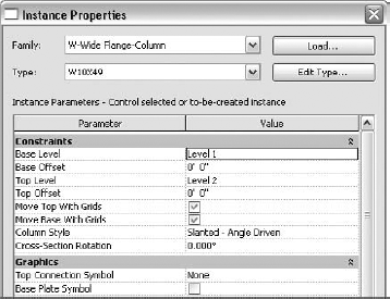
Figure 4.25. Setting the top and base of a slanted column's constraints to a grid in its Instance Properties dialog box
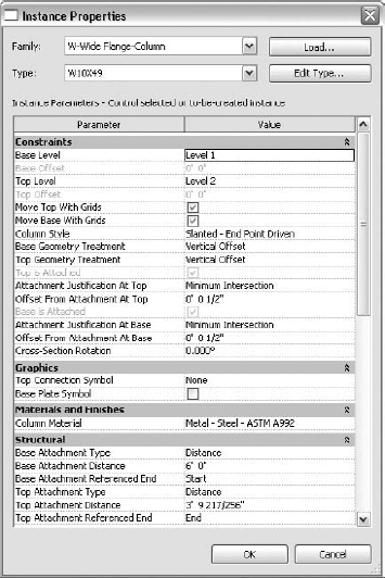
Figure 4.26. When slanted columns' top and base are attached to other elements, several properties become available to control their position.
Hmmm, a Wall for a Column
If you are trying to model a concrete column that includes a taper, slope, or other odd configuration, consider using a wall. You can duplicate a wall and assign it a specific name, like Sloped Column - 24″. The wall can be modeled to the extent of the column shape, and then you can edit the profile of the wall by choosing Edit Profile from the contextual tab on the Ribbon when the wall is selected. In Edit mode, you can add, remove, or rework sketch lines to produce the shape of the column. Here is an example of a concrete sloped column with a concrete beam running over its top. The slanted column is modeled as a wall with its profile edited to create the shape of the column.
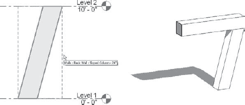
This method will give you a column with the appearance of a sloped concrete column, but it will still have the properties of a wall and schedule as a wall. You can generate other forms with this method. If you are looking only for appearance, then this might work for you.
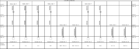
As you probably already know, a Graphical Column Schedule (GCS) is extremely useful for describing the size, reinforcing, and connection information for columns on a multistory structure in an elevated graphical display rather than the standard method of using a mark number and text-only schedule. Revit Structure automatically keeps track of any structural column that is placed in your project and links it to a grid intersection. If it is not on a grid, Revit Structure will link the column to the nearest grid. Not only can the GCS shown in Figure 4.27 be used to document the information pertaining to your structural columns, but it can also be used to keep track of information while you are working and help maintain the integrity of your model.
Since GCSs are a completely different schedule (they are a hybrid of a schedule and many little section views) than Revit Structure's Standard Schedule, they get their own category in the Project Browser called Graphical Column Schedule. (We'll discuss how to create a Standard Schedule in Chapter 11.)
The basic procedure to create a GCS goes like this:
Select the View tab
Note that if gridlines are not present in your project or the 3D extents of at least two grid intersections do not cross the plane of a structural column, you'll see the warning, "No columns are joined to grid lines, or view parameters exclude all columns." Revit Structure will create a new GCS view but will not generate a schedule displaying column information.
Right-click the new GCS view in the Project Browser and select Properties, or right-click anywhere in the view itself and select View Properties.
Make changes to the view's properties to give it the final look you want.
Once the GCS is placed on a sheet, change the settings to allow you to split the schedule onto multiple sheets. (You can learn more about placing GCSs on sheets in Chapter 12.)
With the GCS, you have access to only a few settings that will allow you to tweak the appearance of the schedule and control the type of columns that will show up in the schedule. There are other approaches that allow you to control the display of the graphics in the schedule, as you'll see in the next section.
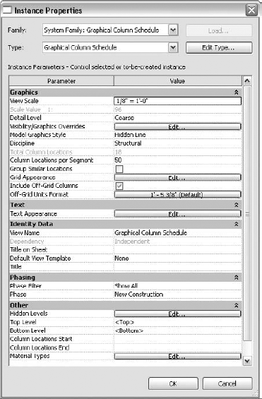
In the Instance Properties dialog box of the GCS (see Figure 4.28), you will find most of the settings for adjusting its appearance and how the information in the schedule displays. We will step through a few of the primary controls to show you how they affect the schedule's display.
The GCS has the same basic properties of any other view that Revit Structure creates, and the properties behave pretty much the same way. There are View Scale, Visibility/Graphic Overrides, Detail Level, and Discipline options. If you set Detail Level to Coarse, Revit Structure will display steel shapes as symbolic lines and include symbol representation for the top and base of column connections. You can apply view templates to the schedule, and it can have its own title separate from the title on the sheet.
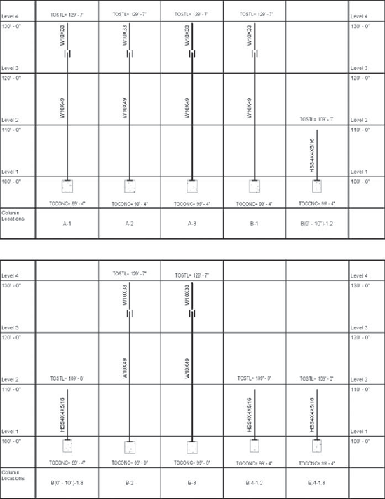
Some projects have several grid intersections with columns, which can make your schedules quite lengthy. For this reason, you can set the number of vertical rows to display in the schedule (Figure 4.29) before the schedule automatically splits into a new segment (it remains part of the same schedule). When you modify Column Locations per Segment, you are specifying the maximum number of vertical rows you want to display.
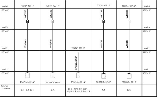
Select the option Group Similar Locations to combine columns that have the same (exact) information into the same vertical row (Figure 4.30). The Group Similar Locations option can also be used to change the properties of a group of structural columns all at once. This approach may be easier than selecting columns one-by-one and changing their properties.
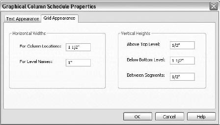
The Grid Appearance tab, shown in Figure 4.31, appears when you click the Edit button for the Grid Appearance parameter in the Instance Properties dialog box for the GCS. You may have to adjust the Horizontal Widths options of the vertical rows to accommodate level names that are too long to display legibly in the schedule. Perhaps you may have to widen the vertical rows where the graphics of the structural columns display to provide adequate room for text in tags.
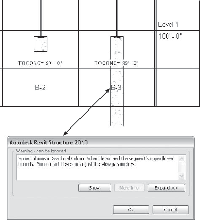
You may also have to adjust two of the Vertical Heights options, Above Top Level and Below Bottom Level, when structural columns exceed the GCS's upper or lower boundaries. As Figure 4.32 shows, the columns in the GCS are shown at their modeled size and length when a column is dropped well below Level 1 for a utility pipe.
The last setting in the Vertical Height options is called Between Segments. Use it to set the dimensions between columns that are broken up into multiple segments, as shown in Figure 4.29. Breaking them into multiple segments will shorten the overall width, thus allowing you to put more than one schedule on a sheet while keeping all information inside one schedule.
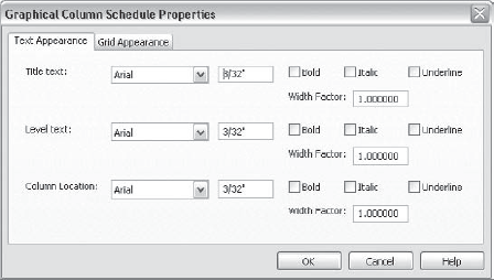
The Text Appearance tab, shown in Figure 4.33, appears when you click the Edit button for the Text Appearance parameter in the Instance Properties dialog box for the GCS. You have seen several images in previous sections that show ways you can display the line work and column information for a GCS. Here you can also make changes to the automatic text that Revit Structure displays in the schedule.
Another way to fit level names that are too long to display legibly in the vertical level row of the GCS is to adjust the text's Width Factor value. When you are grouping similar columns, you can also do this in the Column Location field. This allows you to fit more grid intersections in the box without having to adjust the width of the grid intersection location row. You can set other text formats, such as bold, italic, and underline, to help achieve the look you want.
Hidden Levels
Clicking the Edit button of the Hidden Levels option in the Instance Properties dialog box of a GCS takes you to the Levels Hidden in Graphical Column Schedules dialog box, shown in Figure 4.34. Here you can turn off the display of a level by clicking its check box. All levels will appear in the schedule regardless of their 3D extents. For example, if you have created levels in your project for the sole purpose of tying together geometry or have levels for both top of slab and steel, select these levels so that Revit Structure will hide them in the GCS.
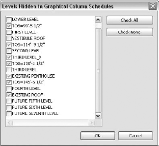
By default, Revit Structure displays the lowest (bottom) and highest (top) levels in the GCS. You can modify the Bottom Level and Top Level settings to display only columns between a specific set of levels.
For example, suppose you have all the columns modeled on your project and you have to issue a Foundation package. You want to include structural column information for only the first lift of columns to obtain dowel reinforcing or anchor rod information. Set Bottom Level to Level 1 and Top Level to Level 2. With these settings, the GCS will show only column information for columns between Levels 1 and 2. When the next issue comes and you need to include the additional column information, you can change the Top Level setting back to the default.
Here's another example: Suppose you want to schedule only the penthouse columns on Level 10. To do so, set Bottom Level to Level 10 and Top Level to Penthouse Roof.
The Column Locations Start and End options work in a similar way to the Top Level and Bottom Level settings, except that they use the grid intersections. You can specify a grid intersection to start from and one to end with.
For example, suppose you have three zones, Zone A, Zone B, and Zone C, and you want to separate your GCS into three different zone-specific schedules. This separation helps anyone reading the documents to easily find the grid intersection. For each GCS, set the Column Locations Start and End options to show only the extent of grid intersections for each particular zone.
Once you have the overall look of the GCS in place and you have it set up the way you want, you can move on to adding annotations to display structural column properties that you need for documentation or to put information into the model.
The biggest display of annotations in the GCS is the tagging that pulls information from the column's properties. Any information that is part of the column's properties can be displayed with a tag that has a direct link to a particular parameter. Another form of annotation is the use of spot elevations for indicating the top or bottom of column elevations. A third form is that steel shapes display symbolic connection symbols when the view's Detail Level is set to Coarse.
These three annotation methods automatically adjust when the GCS changes form or when columns shift within it. Tags and spot dimensions maintain their relationship to the columns as other columns are added to the schedule, forcing them to shift down the line. You can add normal text as annotations, but this text will not move as the schedule changes. You will have to visually check the text for proper placement and manually move it.
Most of the parameters that you tag are either project or shared parameters. When creating such parameters, you must specify Instance or Type. You establish each parameter depending on the type of project and the various stages of packages you need to issue.
Figure 4.35 shows a typical steel column, which can display information such as the following:
Size of the member
Base plate size
Anchor rod size
Anchor rod embedment length
Layout type
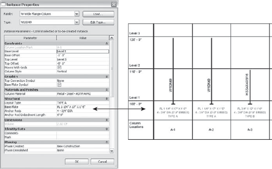
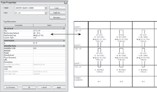
Figure 4.36 shows a typical concrete column, which can display information such as this:
You add text parameters for this information to the structural column families. Tag families are created with labels that pull the required information from the properties of the columns to be displayed in the GCS. You can combine multiple labels inside one tag as well as add a prefix and/or suffix to the information that is being display. For example, within the properties of the column you can specify an anchor rod's information and its embedment as two separate parameters. The value for the embedment can only read 0′-9″. When you create the label, you can string the two parameters together with a suffix so it all reads continuously on one line as 4 - 3/4″ DIA (0′-9″ EMBED). The same method can be applied for information in concrete columns such as VERTICAL and OC TIES. It is not necessary to call this out in the parameter value when it is already mentioned in the parameter name. Build it directly into the tag.
You can add spot elevations to the GCS by selecting the Annotate tab on the Ribbon and choosing Spot Elevation from the Dimension panel. As Figure 4.37 shows, not only can you use spot elevations to indicate the top and bottom elevations of columns and any other elevations that you need for documentation, but you can also use them to help control the placement of the column geometry in the model. A GCS you create simply to help control the placement of the column geometry and serve as a model consistency check can be maintained easily.
You know that Revit Structure displays symbolic symbols for steel shapes and their connection types in other views when they are set to a coarse detail level; the GCS does the same thing. Chapter 2 describes in great depth how Revit Structure controls these symbols for a structural column and how to create new ones as well as set their display for a project. Since structural steel is usually shown with single symbolic line work, these symbols are available only when you're working with steel shapes or families that have Structural Material set to Steel. If available for a structural column, these symbols can be found in the Graphics group of the column's properties. Making use of their display in the GCS will put the finishing touches on a well-displayed and well-documented schedule.
Modeling Base Plates
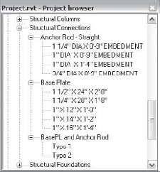
Revit Structure offers families for placing base plates as modeled geometry into your project. You can load these families from the Imperial LibraryStructuralConnections folder. These families are face based and are part of the Structural Connection category. We attempt to take these families to the next level so we can schedule them and so they can serve as an interference check for the architect when plates and bolts tend to project outside a wall or column enclosure.
We continue to experiment with placing base plates as modeled geometry in each project, along with using text-based parameters in schedules for our documentation. Typically each new version lets us take this concept a bit further. Modeling base plates is probably not a wise approach for all your projects, so do it selectively. Keep in mind that modeling this amount of detail in a large project can decrease the performance of the model. We feel that eventually the software will catch up to this level of detail, so we are trying to dig in at whatever level we can to keep the BIM method of thinking going.
For example, we decided to develop anchor rod and a base plate families and set each as shared in the properties. We nested the new families inside the base plate connection family so that we can place them into a project as base plate connections. Since we specified these families as shared, they show up as individual families under Structural Connections in the Project Browser, as shown here. Therefore, we can easily duplicate them and create new sizes as needed.
In the base plate connection family, we can select the anchor rod and base plate types (using a Family Type parameter) to create base plate connection types, which we can then schedule. These families eventually can become attached to columns when we place them into a project. Here is the overall look of the concept.
This is now a pretty advanced family and reacts well when properties of the elements change. When the anchor rod size changes, the grout changes with it, and the holes in the base plate change in size accordingly. Also, when the base plate changes size, the anchor rods and its components change with it. Visibility and subcategories are also assigned to the different components. This way, only the base plate displays at the medium detail level; everything shows up at the fine detail level. We can turn off components in the Visibility/Graphic Overrides dialog box of the view from the subcategory setup.
We continue to look at this concept, and the process still has a few kinks we need to work out. A few questions come up. For example, should this base plate, grout, and anchor rod be part of the column family, or should it be a stand-alone connection as it currently is? What happens when there are more than four anchor rods? We hope that the ability to push the limits of Revit Structure in this way will eventually become part of the GCS.
As you can guess by the name Graphical Column Schedule, all columns displayed are graphically shown as their geometry. Earlier we discussed setting the appearance of the columns: We explained how you can set a steel column to display as a symbolic line, and you learned that concrete columns are usually shown as double lines. Now let's discuss what you do once the columns are actually in the schedule.
What determines that a column is put into the schedule? What do you do if columns don't show up in the schedule? What happens when you don't want certain columns to show up in the schedule? These are questions that you are going to want answers for when you're working with a GCS. Knowing these answers will help you create your schedules quickly and ensure that only the desired columns display.
Revit Structure gives you the ability to display only those columns that are on grids or those that are offset, and it still gives those columns a location mark based on the grid names that are intersecting them. Revit Structure creates the location marks automatically using a set of rules. In some cases, the program tries to be flexible in allowing you to choose what is displayed. After determining the best grid to reference, Revit Structure displays this value in the properties of the columns, under the Constraints group in the Column Location Mark parameter. If more than one grid can be referenced to the offset column, Revit Structure allows you to select which column location mark you want to display. Figures 4.38 and 4.39 show that the read-only behavior of this parameter changes depending on where the column is located.
Automatically scheduling offset columns, determining their location mark, and giving the user a bit of flexibility can be complex. You may have to resort to other methods to get the GCS to perform the way you want it to.
In the properties of a GCS, you can choose Include Off-Grid Columns. With this option checked, all columns—regardless of their placement on a grid—should be placed in the GCS as long as the 3D extents of the grids cross the horizontal and vertical planes of the column(s). Revit Structure will continue to give the offset column a location mark referencing the closest grid intersection based on a set of calculations.
Figure 4.40 shows that if an offset column's bounding box (the extent of its geometry) intersects or its edges touch a grid, its location mark will reference the closest grid intersection.
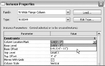
Figure 4.39. The Column Location Mark parameter's read-only behavior is sometimes removed to allow you to select a different location mark.
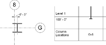
Figure 4.41 shows that if an offset column's bounding box (the extent of its geometry) does not intersect or its edges do not touch a grid, its location mark will reference the closest grid intersection, with an added annotation indicating the offset from the referenced grid.
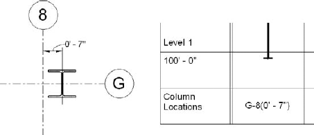
Figure 4.41. Offset columns with a bounding box not intersecting the grid are noted with an added dimension in the location mark.
Also included in the properties of the GCS is a setting called Off-Grid Units Format. This setting, which behaves just like any other unit format override (similar to dimensions), is located just below the Include Off-Grid Columns parameter. This override allows you to have some control over the display of the offset dimension value that is placed after the grid mark in the Column Locations row.
How the GCS displays and annotates offset columns may not be to everyone's liking. Remember that a simple rotation or size modification of an offset column can change what gets displayed for its Column Location in the GCS. An offset column is not necessarily denoted as being offset. To avoid this behavior, sometimes a quick duplication and modification to an already created structural column family will do the trick. If that doesn't quite work, you might want to try creating extra grids that will keep the column on a grid intersection. Any of these methods will work, but you will have to decide which one is best for each particular project.
In this first method we'll discuss how you make a few quick edits to an existing column family (or if you are creating your own family, keep these edits in mind). In short, you will make changes to the column family that allow Revit Structure to shift what it considers the center of the column. Make sure that you are not making changes to the normal structural column family, but that you save this family under a different name using a suffix of -Offset or something similar. One of the rules for displaying a structural column in a GCS is that it must be centered on a grid intersection (unless you have the Include Off-Grid Columns parameter checked). We'll make a few quick edits to a duplicated structural column family so it has instance parameters to adjust the location of the Center (Left/Right) and Center (Front/Back) reference planes inside the structural column family. The basic procedure looks like this:
Edit or open a column family that will be uniquely named for its offset behavior.
While in the floor plan view: Lower Ref. Level, create new reference planes parallel to both of the Center (Left/Right) and Center (Front/Back) reference planes.
You can find these reference planes by viewing their properties and looking at the Is Reference value. These reference planes should currently be placed at the center of the column.
In the properties of the new reference planes, reassign the Is Reference values to the appropriate center name in the pull-down menu and select the Defines Origin check box.
This step will automatically set the old reference planes located at the center of the column to Not a Reference and set the origin of the column to the new reference planes' intersections.
Place a dimension between both of the reference planes, as shown in Figure 4.42, and add an Instance parameter label to them defining the column offset.
After loading the family into the project, you can use your new family when you want to display an offset column. Just make sure that you are placing the column so the reference planes in the family that are defined as the origin are located on the grids that create the intersection. If using this method is not feasible, consider using another grid type as a centerline and using a unique grid name mark to display in the GCS.
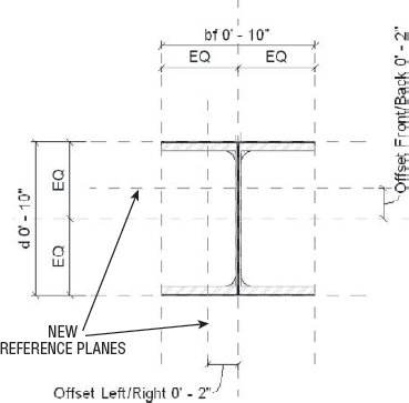
In our next example, you create a new grid type by duplicating your standard one and naming it something like Centerline. Set its Type Parameter: Symbol value to None so you will see the gridline only when you place it in your project. Assign a color to it so it stands out from your normal grid when viewing it on screen. Place your offset columns on this grid line. Since it is still a grid, you will have to give it a name and set its 3D extents. If the grid you want to associate it to is named Grid C-2 and its offset is from Grid C, then you could name the Centerline C* or something similar. It would then show up in the GCS as C*-2, as shown in Figure 4.43.
You can add a note to the bottom of the schedule that states something like this: "Columns shown in schedule with '*' after the grid name indicates columns that have been offset from a grid. See plan for offset dimension." This approach allows you to see the offset centerline in all views because it behaves as a grid; since the grid type is not assigned a symbol, the bubbles will not display either. An offset column usually needs a centerline to denote its offset dimension, which makes this method easy because you don't have to place a separate detail line in every view in which you need to show the column.
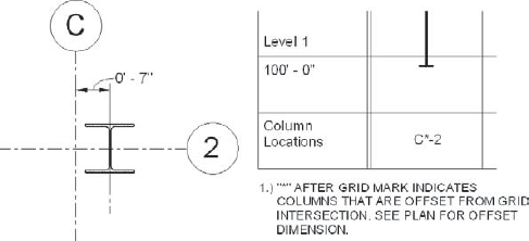
Earlier we discussed setting the Structural Material property for a structural column family. Not only does this setting dictate how members frame to the column or how it displays in views, but it can be used to display or not display columns in the GCS. To use the Structural Material property to display columns in a GCS, first open the GCS's Element Properties dialog box. Under the group Other, you will find an Edit button. Click this button to open the dialog box shown in Figure 4.44. By default, Revit Structure has all five material types checked. Deselect any you don't want to include in that GCS.
This method of displaying columns can be useful when you have certain columns with material types that you don't want to appear in the GCS. Maybe you have a few wood columns scattered throughout a project or a concrete structure that has a few steel columns that will be scheduled in a Basic Schedule. Deselecting those structural material types will remove them from the schedule.
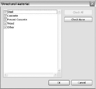
If you want only a portion of those steel, wood, or concrete columns removed, you will have to apply phasing or some additional filters to remove them in a more selective way.
Applying phases to a GCS works the same way that it does when applying them to other views. The GCS provides a phase and a phase filter that you can apply to help drive which columns will be displayed. We'll discuss phases in much greater depth in Chapter 16. The same methods and procedures discussed in that chapter can be applied to the GCS.
You can use phases to help control the visibility of existing columns in the GCS. This is probably the easiest way to remove them from the schedule (as long as you are assigning these elements to the Existing phase by setting the Phase Created parameter to Existing). Follow these steps:
In the properties of the existing column, make sure the Phase Created parameter is set to Existing.
Right-click in the GCS's view and select View Properties, or right-click on the GCS's name in the Project Browser and select Properties.
Set the value of the Phase Filter option located in the Phase group to Show New. Click OK to go back to your GCS.
Those columns for which you set the Phase Created parameter to Existing have disappeared from the schedule.
You can use phases to display columns in the GCS depending on the project stage. You may even create schedules just to see how columns are modeled or to reveal the various stages at which they will be issued. When using phasing does not quite get you 100 percent satisfaction, you can apply filters, as you'll see next.
Filters let you be a bit more selective in determining what columns show up in the GCS and—in some cases—how they display inside it. Filters can be a selection of elements that you save or a set of rules that you put in place to determine what is put into a selection set as your model progresses. Figure 4.45 shows a Define Criteria filter called Do Not Schedule that does the following: It finds all the project elements from the Structural Columns category, and if the value of an element's Comments parameter equals Do Not Schedule, then that element becomes part of the selection set. As this parameter value changes, columns continue to be added or removed from the selection set that the filter creates. This can be a much better method than just saving a selection set and manually having to add and remove elements as they are modeled in your project.
After your filter is created, you will have to apply it to the GCS view using the Visibility/Graphic Overrides dialog box.
To make a Selection Set filter, perform the following steps:
Select the elements that you want to be part of the set.
Choose the View tab
In the Filters dialog box click the New button to create a new filter.
Give the Selection Set filter a name that reflects its purpose and choose Use Current Selection. If elements are not selected, you can choose Select to be given the option to make a selection.
Continue to click OK to close out of all open dialog boxes to finish.
Then you have to apply this filter to a view in the Visibility/Graphic Overrides dialog box.
To create a Defined Criteria filter (which is rule-based), follow these steps:
Choose the View tab
In the Filters dialog box click the New button to create a new filter.
Select the Define Criteria option and assign your filter an appropriate name.
Apply the appropriate settings (such as the categories that the filter will apply to), and then specify any rules that will apply to the filter.
Continue to click OK to close out of all open dialog boxes to finish.
After you save your filter, you can add or remove elements or change the filter rules (choose the View tab
To apply a filter to a GCS view, perform these steps:
While in the properties of the GCS view, click the Edit button next to the Visibility/Graphic Overrides parameter.
Select the Filter tab at the top of the dialog box to access the filter settings.
Click the Add button to add an already created filter or click Edit/New to create a new one.
After you add the filter on the Filter tab, you can make changes to the filter's elements.
Deselecting the Visibility option will remove any structural columns that are part of the filter from the GCS. You can also apply other override settings to change the look of the graphics of the scheduled columns.
Filters can be powerful tools for developing GCSs that will help you document your model. In some cases, you can use existing parameters such as the Comments field, or you may need to create your own. Filters can be used to help create separate GCSs for zones of a building.
Adding a parameter called Scheduled Zone will allow you to give each structural column a property indicating the zone the column belongs to. You can use a filter to select only those columns in a particular zone. Each time you create a GCS, those filters are applied to show only the columns for a particular zone.
Adding a parameter called Column Usage will allow you to give each structural column a property explaining its purpose in your project. Maybe the column is being used as a pier, or a hanger, or even a smaller post, and you don't want it to show up in the GCS because it will be scheduled with a different method. You can apply such values as Pier, Hanger, or Post and use filters to prevent those columns from displaying in your GCS.
As you can see, the possibilities of using filters in the GCS are endless. They can give you the freedom you need to produce great-looking column schedules. You can take advantage of filters in any other view throughout a project using the same procedures and methods. When used properly, filters are a great way to add flexibility when producing your documentation.
- Work with the basic structural column family template
Understanding the differences between the various templates for a structural column will help you ensure that your structural columns behave properly when placed into your project.
- Master It
What setting in a structural column family gives it the characteristics that help Revit Structure determine connection and attachment properties and whether the columns display in the Graphical Column Schedule?
- Place structural columns in your project
Knowing all the methods available for placing structural columns in your project and knowing when to use each one will help you place columns quickly and accurately into your project.
- Master It
What are three options you can use to place structural columns in your project, and how can you quickly place them onto the upper levels?
- Attach structural columns to other structural components
To help maintain the top and bottom of a column's location and their relationship to other elements, they can be of different cut styles and justifications while being attached to various elements.
- Master It
What types of elements can structural columns be attached to?
- Employ the methods of placing slanted columns
Revit Structure allows you to place slanted columns into your project using similar methods used to place vertical columns. As you attach the top and base of a slanted columns to levels, you can set the slanted column's properties to determine how they behave when those levels are modified.
- Master It
What view type does not allow a slanted column to be placed, and what are the two properties that can be specified in the Column Style setting to control how slanted columns behave when their top and base locations are modified?
- Document your model with the Graphical Column Schedule
The Graphical Column Schedule can be generated automatically by Revit Structure and modified to exclude columns that you do not want displayed.
- Master It
What methods are used to remove structural columns from the Graphical Column Schedule?