
6
Shared Aperture Antenna with Pattern Diversity for Base Stations
6.1Introduction
The tremendous recent increase in data-hungry applications, especially with respect to smartphone users, has encouraged researchers in academia and leading research organizations to look for the design of hardware ecosystem at 28 GHz and beyond for future 5G cellular systems, primarily because of spectral congestion in the sub-6 GHz bands. Path loss for mmWave communication links is high; for example, for a 10 m link at 28 GHz, the path loss is 82 dB as against 60 dB for the same distance for the existing commercial 4G cellular link. The penetration losses are also high (>20 dB) for the 28 GHz for common building materials such as concrete and brick [1].
In order to establish a reasonable communication link, high-gain antennas must be deployed at the base stations and mobile terminals to compensate path loss, as noted in [2] for the proposed 5G band. But high-gain antennas would necessarily mean low beamwidth, thus leading to poor coverage. Base station antennas must have reasonably high gain, therefore high gain antennas with the smallest physical footprint would be ideal candidates for 5G base station operation in the 28 GHz band. High gain antennas could be designed using phased array schemes such as given in [3,4], but the configuration of phase shifters and the controllers for beam-locking for the communication link would be challenging to design. Also, an N-port phased array system (N>4), which would create a resultant beam at 0° and 90°, would suffer from scanning loss and hence lead to gain deterioration away from the boresight. As the beam is scanned away from 0°, the side-lobe level also increases, therefore antennas with orthogonal pattern diversity are preferred. It must be noted that pattern diversity architecture also increases the data throughput of the communication system. Shared aperture antennas could be redesigned for mmWave 5G base station to achieve high gain with pattern diversity and the smallest physical footprint. The pattern diversity topology suggested in [5] has four orthogonal ports with low mutual coupling in the 2–20 GHz band; shared aperture is not a feature. Shared aperture proposed in [6] does not have independently controllable patterns. It must also be noted that the gain variation between the two modes of operation is more than 2 dB across the bandwidth because of the dual beamforming. Gain enhancement architecture with zero index metamaterial (ZIM) loading proposed in [7] would operate only for the designed incident polarization. Similarly, the metamaterial superstrate presented in [8] is sensitive to the incident polarization, and the decoupling strategy might not be operational for orthogonal incident waves. Miniaturization techniques such as the integration of a modified circular slot ring resonator (CSRR) with the antenna would yield a compact design with a compromise in gain [9], hence proving unsuitable for base station applications. Shared aperture design targeting satellite applications [10] has a compact design but the gain variation across the ports or bands is noticeable. Thus, in order to achieve uniform gain for orthogonal ports with minimal physical footprint, a shared aperture antenna with dual-polarized zero-index metamaterial (DPZIM) unit cells is proposed. A shared aperture antenna with orthogonal pattern diversity is presented in this chapter. A dual-polarized metamaterial unit cells is designed and characterized with identical characteristics for both of the incident polarizations. The proposed unit cells are strategically integrated to the shared aperture antenna to achieve gain enhancement, gain equalization across the ports and the band, along with reduction in mutual coupling.
6.2Shared Aperture Antenna
The deployment scenario of the 5G base station module is evident from Figure 6.1(a). In order to achieve this, a shared aperture antenna with orthogonal pattern diversity is proposed. The schematic of the proposed antenna with shared aperture and pattern diversity is depicted in Figure 6.1(b), and the corresponding photograph is shown in Figure 6.1(c). The structure is designed on Nelco NY9220 with a dielectric constant of 2.2 and 20-mil thickness. A low dielectric constant was chosen to reduce additional surface wave modes, and an electrically thin substrate would reduce cross-polarization radiation in end-fire. Typically, substrates are characterized for the dielectric constant at 10 GHz, and the manufacturer would specify the tolerance for the substrate. In this case, the dielectric constant varies within 2.2 ± 0.02. It would be good design practice to measure the dielectric constant of the available substrate in the desired frequency by making a ring resonator or a standard inset-fed patch antenna. The loss tangent could also be discovered by measuring the transmission loss for a standard 50 Ω line for a 50 mm line of the substrate in a properly calibrated vector network analyser. It is also recommended to measure the thickness of the substrate using digital Vernier calipers or a digital screw gauge. The thickness of copper would be 15–35 μm. The thickness of the copper would not affect the performance of the antenna, but would decide its power handling capacity.
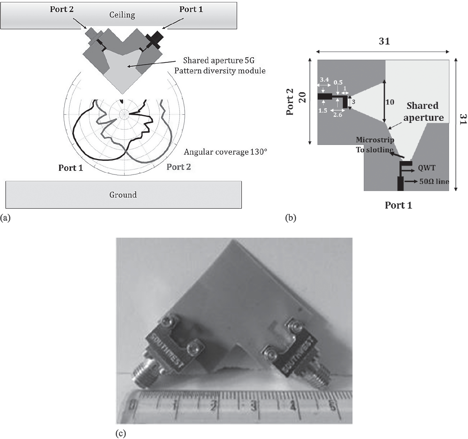
Figure 6.1
(a) Typical deployment scenario of the antenna, (b) Schematic of the proposed shared aperture antenna and (c) Photograph of the shared aperture antenna [24].
The feed line is a standard 50 Ω line of width 1.5 mm, in series with a quarter-wave transformer (QWT) of 96 Ω with a line width of 0.5 mm transitioning to the microstrip with a slotline transition of 194 Ω. Two antennas with identical flare angles of the radiating aperture are merged into a single shared aperture with a port-to-port distance of 30 mm. The elements could be designed to be electrically closer, but this would result in the degradation of mutual coupling and radiation characteristics, hence the chosen topology is a compromise between mutual coupling, beam integrity across band and gain with least physical footprint, for a compact antenna with pattern diversity across the 27–30 GHz band for 5G base stations.
The flare angle of the radiating aperture is designed for optimal beamwidth in the end-fire. The shared aperture increases the mutual coupling between the two orthogonal ports. The structural asymmetry leads to variation in radiation pattern variation across the band. The shared aperture is designed with tapered slot antennas, since the beamwidth could be engineered for the application in hand. Tapered slot antenna (TSA) elements also offer high beam integrity throughout the operational spectrum. Previously reported orthogonal pattern diversity antenna modules have gain variation across the band and across the ports because of the utilization of different class of antennas for orthogonal beams. Leaky wave topology would be unable to maintain radiation pattern integrity when the beam is excited for a 90° tilt with respect to boresight. Similarly, phased array architecture reported in the literature suffers from a scanning loss of almost 2 dB for a beam tilt of 45°, hence for a beam scan at 90° the scanning loss would be higher, leading to increased degradation of the patterns.
The E-field plots for both the ports at 28 GHz are illustrated in Figure 6.2. The quasi-cylindrical wavefront at the edge of the physical aperture is evident, which creates a larger error in the phase front, leading to a lower gain for both the ports. The mutual coupling is also evident from the figures.
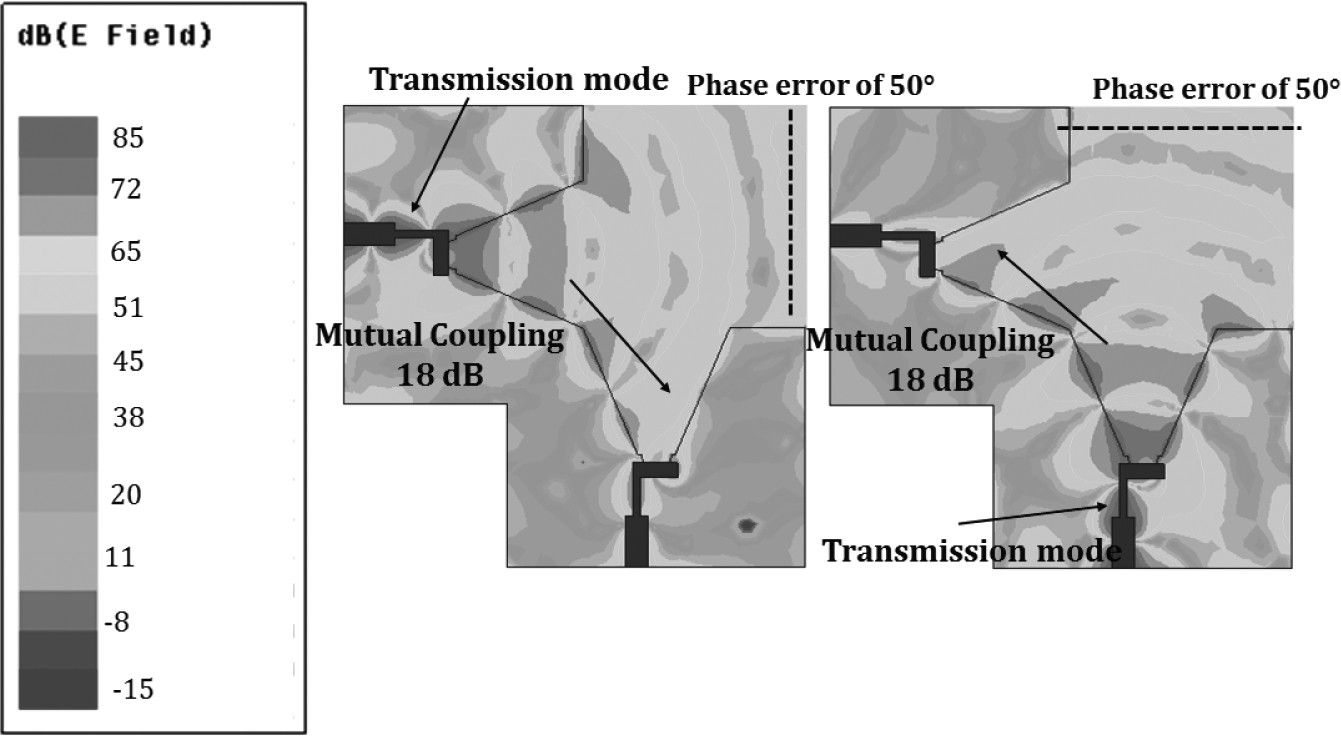
Figure 6.2
E-fields for port excitation at 28 GHz, (a) port 2 and (b) port 1 [24].
The simulated and measured S-parameters for both of the ports are depicted in Figure 6.3. The impedance bandwidth for the shared aperture element is 27–30 GHz (10%). The impedance bandwidth could be enhanced by replacing the stepped impedance transformer with a wideband balun, but this would lead to pattern distortion at the higher end of the spectrum, leading to significant variation in gain. The impedance characteristics are similar for both of the orthogonal ports. The measured mutual coupling is in the range −17 dB to −19 dB in the 27–30 GHz frequency band. The mutual coupling is high because of the shared aperture and the ports being electrically close. The electrical distance is designed for an optimal mutual coupling and beam integrity.
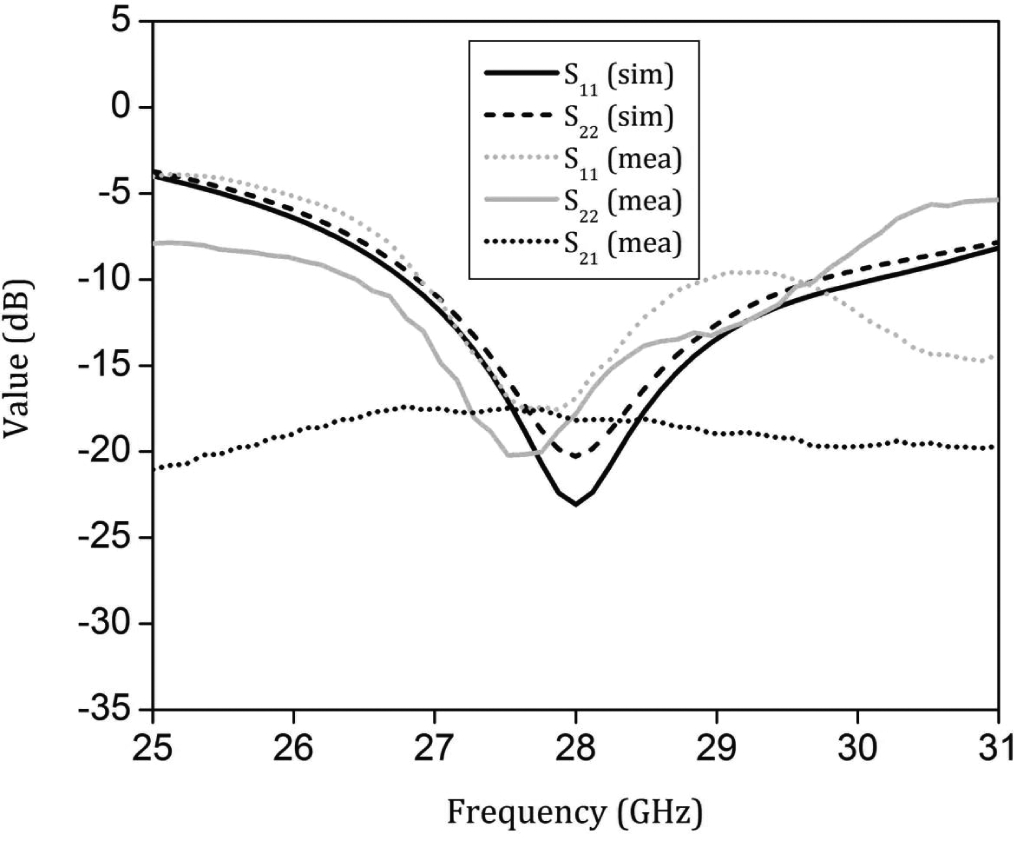
Figure 6.3
S-parameters of the proposed shared aperture antenna [24].
6.3DPZIM Design and Characterization
The end-fire gains of the proposed shared aperture antenna vary between 7 and 8 dBi. In order to enhance gain with the same physical footprint, the integration of metamaterial unit cells is investigated. Typical gain enhancement technique such as quasi-Yagi topology is strongly polarization sensitive and hence, in the context of shared aperture, gain enhancement would be achieved in one of the orientations in addition to degrading the far field patterns of the orthogonal port. The zero-index metamaterial unit cells proposed in the literature are also strongly polarization sensitive, therefore the integration of these unit cells might not be optimal solution for simultaneous gain enhancement across the ports with a reduction in mutual coupling. The design evolution of the unit cell is depicted in Figure 6.4.
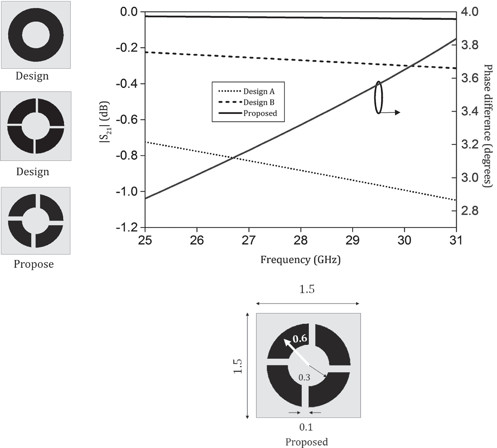
Figure 6.4
Design evolution and the proposed unit cell [24].
To achieve gain enhancement in dual polarization modes, the insertion loss (|S21|) must be minimal and the unit cell must create a reasonable alteration of the phase of the incoming wave. As observed in the S-parameter curves, the circular ring has a high insertion loss. Design B has a relatively lower insertion loss, but the relative phase difference is insignificant, hence the proposed design has the least insertion loss with a substantial phase difference, as seen in the figure. The orthogonally symmetric slots act as capacitors, and the arc-shaped stubs act as inductors, leading to a near zero refractive index, as illustrated in the extracted parameters in Figure 6.5 in the frequency of interest (27–30 GHz). The parameters are extracted by the method described in [15]. The orthogonally symmetric slots aid in the polarization insensitive action of gain enhancement. The capacitive slots could be radially increased for a multiport polarization, but the gain yield post integration would be minimal. The gain enhancement would be optimal when the polarization of the incident E-field matched the slots of the unit cell, which in turn would reduce the phase error of the E-plane across the physical aperture and hence effectively increase the radiating aperture.
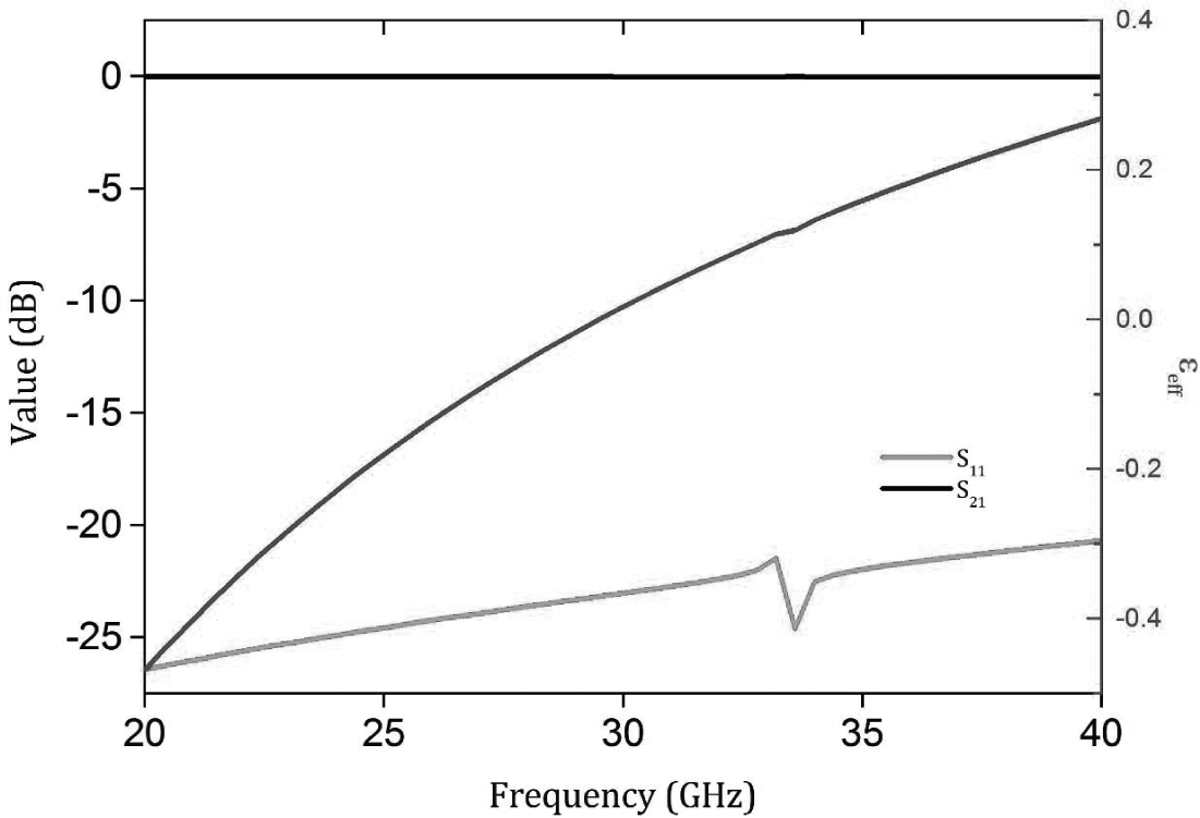
Figure 6.5
Extracted parameters of the unit cell [24].
6.4Shared Aperture Antenna with DPZIM
The E-field plots post integration with the DPZIM unit cells is shown in Figure 6.6. The planarization of the cylindrical wavefront is evident for both the ports compared to the plain shared aperture antenna presented in section 6.2. The strategic loading of the unit cells is designed for gain enhancement, and gain equalization of the ports with simultaneous reduction in mutual coupling between the ports.
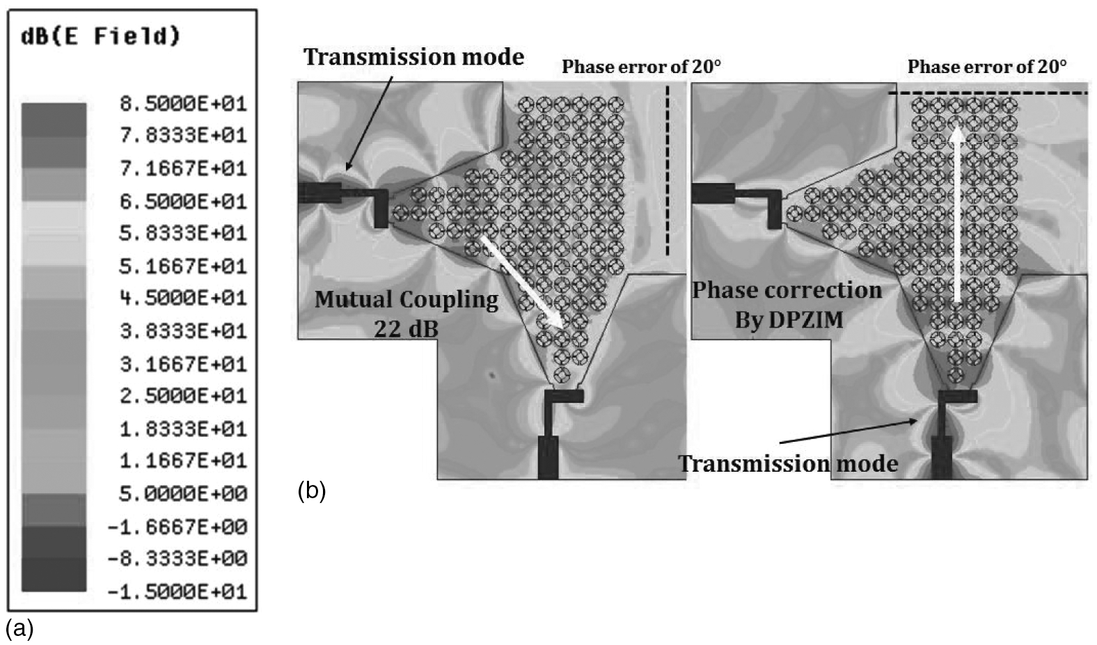
Figure 6.6
E-field plots at 28 GHz, (a) port 1 and (b) port 2 [24].
The polarization insensitive nature is operational in the shared aperture topology. The orthogonal slots of the unit cell match the orthogonal polarization of the ports of the shared aperture antenna. The normalized phase distribution with and without the integration of DPZIM is demonstrated in Figure 6.7. The phase error across 1λ has been reduced from 50° to 20°, hence leading to gain enhancement of more than 2 dB across the band and the ports. The schematic of the proposed element, along with the photograph, is shown in Figure 6.8.
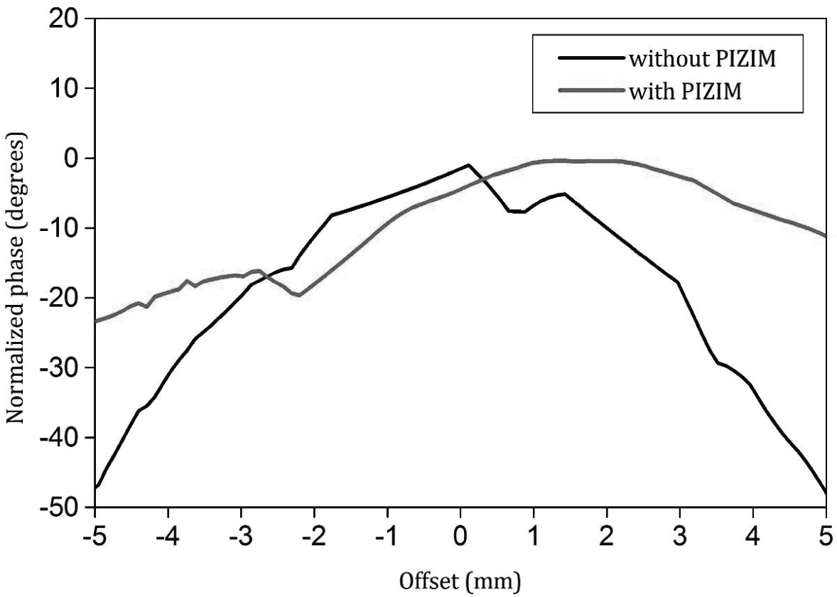
Figure 6.7
Normalized phase distribution at 28 GHz [24].
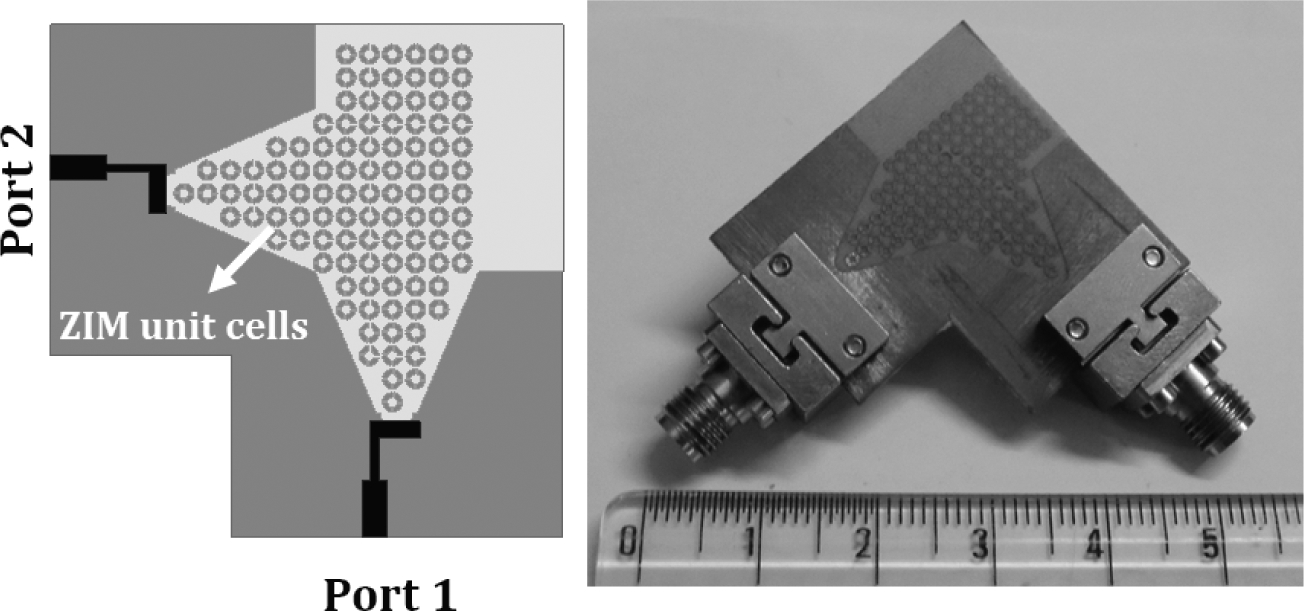
Figure 6.8
Schematic and photograph of the proposed DPZIM antenna [24].
|S11| and |S22| of the respective ports remain almost unaltered post integration with the DPZIM, as illustrated in Figure 6.9 primarily because of the minimal effect on the microstrip to slotline transition of the antenna. The measured mutual coupling for the ZIM loaded shared aperture antenna is in the range −23 dB to −20 dB in the 27–30 GHz frequency band, hence a decrease of more than 3 dB across the band is observed. Since the mutual coupling is reduced, this would lead to higher isolation between the ports, leading to radiation patterns with higher beam integrity in the frequency of operation. The simulated and measured end-fire radiation patterns, with pattern diversity at 28 and 30 GHz, are shown in Figure 6.10(a) and 6.10(b). It must be observed that beamwidth is 40° ± 5° for each of the ports in the frequency of operation. The patterns are stable across the band for both of the ports. The front-to-back ratio is more than 15 dB and the patterns are orthogonal, hence proving its utility in a typical 5G base station.
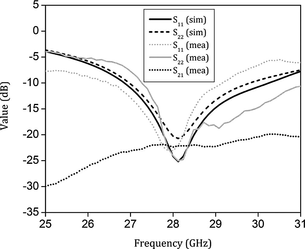
Figure 6.9
S-parameters of the proposed DPZIM antenna [24].
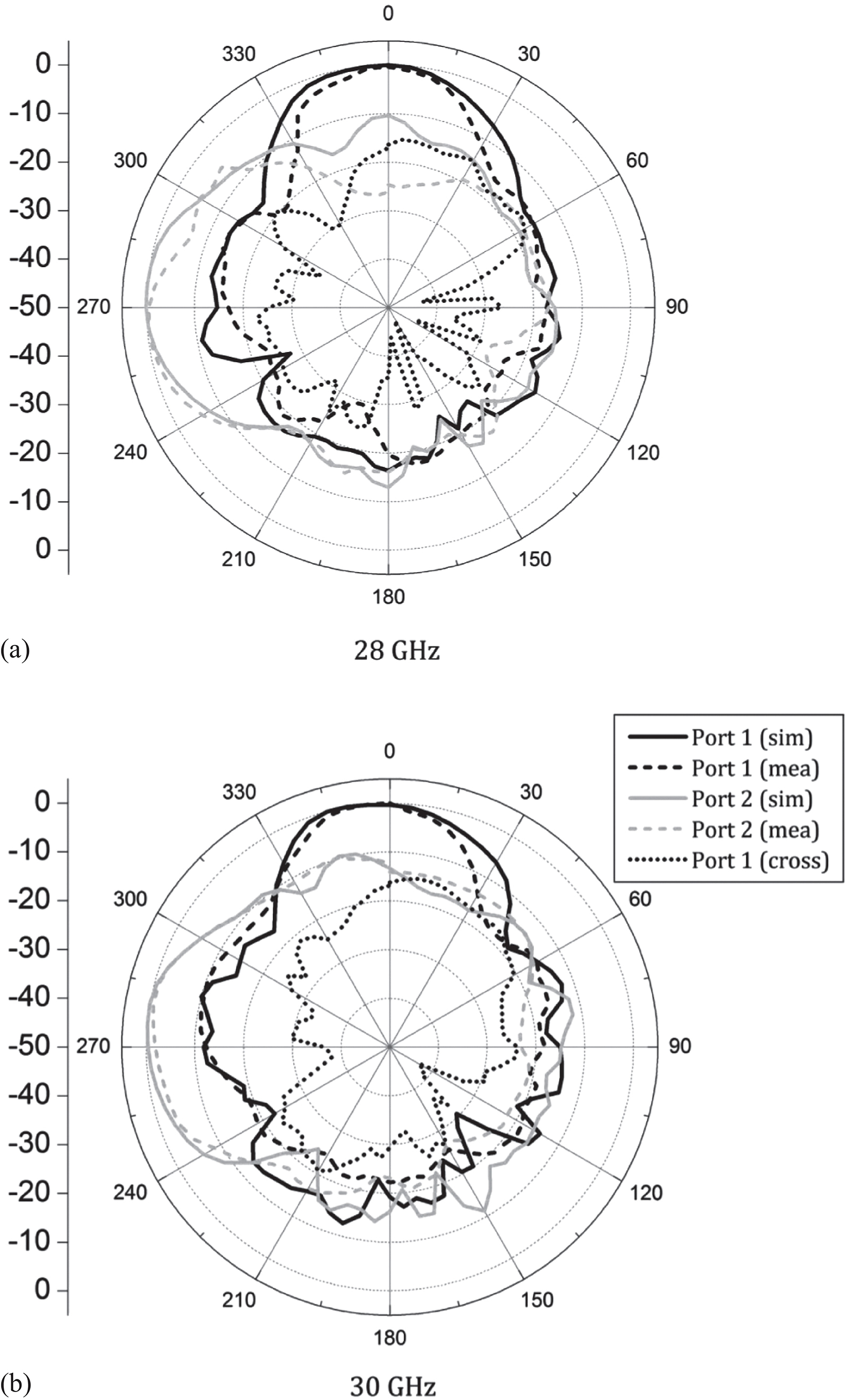
Figure 6.10
Radiation patterns at (a) 28 GHz and (b) 30 GHz [24].
The discrepancy between the simulated and measured radiation characteristics is primarily a result of the effect of lossy adapters and other transitions utilized for measurements. The flaring angle of the shared aperture decides the beamwidth. The current topology is optimized for low beamwidth, consequently leading to higher gain, which is essential to maintain a fair communication link budget in a standard communication setup to compensate high path loss in the 27–30 GHz frequency band.
The simulated and measured gains for each port are illustrated in Figure 6.11. It is observed that the end-fire gains of the orthogonal ports is 7–8 dBi without the integration of ZIM unit cells, and the gain variation is almost 1 dB between the ports because of the asymmetry in the dielectric loading of the shared aperture. The simulated gain after integrating with ZIM is in the range of 9.2–9.6 dBi for both the ports for the 27–30 GHz frequency range, and measured gain is in the range 8.5–9.2 dBi for the 27–30 GHz frequency band. The discrepancy between simulated and measured gain could be attributed to frequency sensitive adapters and other transitions utilized in the standard gain transfer method.
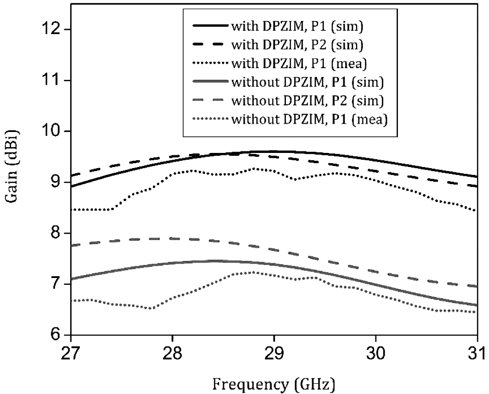
Figure 6.11
End-fire gains of the proposed antennas [24].
Table 6.1 illustrates the features of the proposed pattern diversity module against other reported designs. It is evident that the 1 dB gain bandwidth is 35%, indicating a wideband high pattern integrity behaviour for orthogonal pattern diversity with minimal effective radiating volume. The proposed metamaterial unit cells operate with orthogonal incident polarizations, compared to most of the reported articles, which have strong polarization sensitivity. Leaky wave topology would be unable to maintain radiation pattern integrity when the beam is excited for a 90° tilt with respect to boresight [12]. Conventional gain enhancement techniques such as loading the antenna with parasitic stubs as in typical Yagi-type antennas [13,14] the parasitic is strongly polarization sensitive and hence would fail to yield
Table 6.1
Comparison with Reported Designs
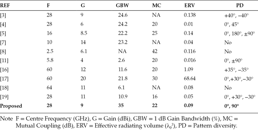
gain enhancement in an orthogonal pattern diversity scenario, as illustrated in Figures 6.12(a) and 6.12(b). It must also be noted that the metamaterial unit cells suggested in the following references [7,8,18,19] operate when the polarization of the incident wave coincides with the polarization of the structure. The proposed dual polarized ZIM unit cells operate for both polarizations of the incident wave, as depicted in Figure 6.12(c). Multiple antenna systems proposed in [20,21,22,23] lack orthogonal beam switching.
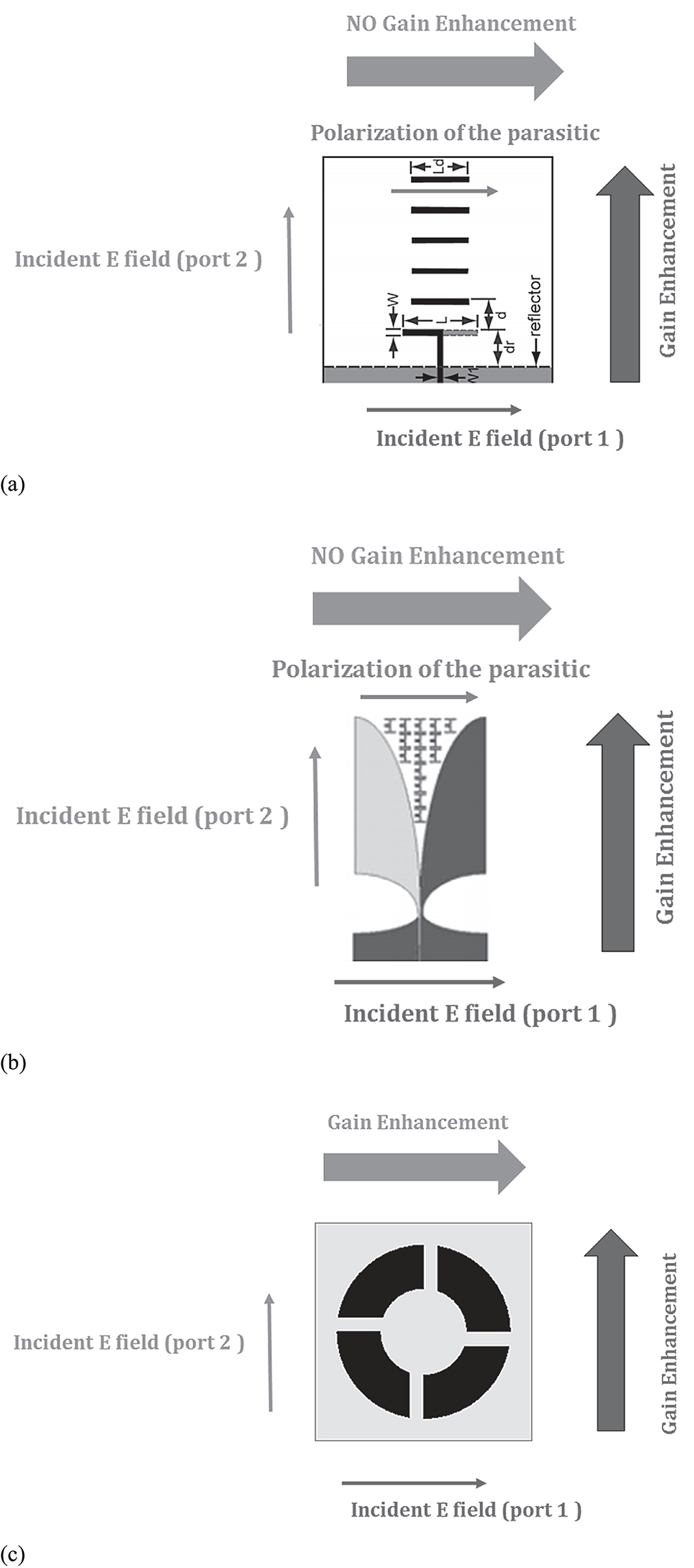
Figure 6.12
(a) Schematic for orthogonal pattern diversity in a Yagi scenario [13], (b) Schematic for orthogonal pattern diversity in a ZIM scenario [18] and (c) Schematic for orthogonal pattern diversity in the proposed DPZIM context.
6.5Design Guidelines for High-Gain Dual-Polarized Antenna Module
-
A compact dual-polarized antenna module must be designed, which could be orthogonal wire antennas or aperture antennas with individual feeds, but the elements must be electrically close to realize the smallest physical footprint.
-
The metamaterial unit cell specifications described in section 4.4 are also valid for a dual-polarized design. In addition to these characteristics, the unit cell must offer them for both the orthogonal incident polarizations to achieve simultaneous phase correction for the corresponding port excitation.
-
The strategic integration of dual-polarized metamaterial unit cells would yield gain enhancement for both the ports with a consequent decrease in the mutual coupling between the ports. The pattern integrity is also decided by the characteristics of the unit cells across the band.
6.6Conclusion
A shared aperture antenna with orthogonal polarization diversity was presented in this chapter. A dual-polarized metamaterial unit cell was proposed and characterized for gain enhancement. The metamaterial loading was designed for wideband high-pattern integrity with orthogonal pattern diversity.
References
- 1.T. S. Rappaport et al., “Millimeter wave mobile communications for 5G cellular: It will work!,” IEEE Access, 1, 335–349, 2013.
- 2.W. Hong, K. Baek, Y. Lee, Y. Kim, and S. Ko, “Study and prototyping of practically large-scale mmWave antenna systems for 5G cellular devices,” IEEE Communication Magazine, 52(9), 63–69, September 2014.
- 3.B. Yang, Z. Yu, Y. Dong, J. Zhou, and W. Hong, “Compact tapered slot antenna array for 5G millimeter-wave massive MIMO systems,” IEEE Transactions on Antennas Propagation, 65(12), 6721–6727, December 2017.
- 4.S. X. Ta, H. Choo, and I. Park, “Broadband printed-dipole antenna and its arrays for 5G applications,” IEEE Antennas Wireless Propagation Letters, 16, 2183–2186, 2017.
- 5.G. S. Reddy, A. Kamma, S. Kharche, J. Mukherjee, and S. K. Mishra, Cross-configured directional UWB antennas for multidirectional pattern diversity characteristics,” IEEE Transactions on Antennas Propagation, 63(2), 853–858, February 2015.
- 6.Y. Dong, J. Choi, and T. Itoh, “Vivaldi antenna with pattern diversity for 0.7 to 2.7 GHz cellular band applications,” IEEE Antennas Wireless Propagation Letters, 17(2), 247–250, February 2018.
- 7.B. Zhou, H. Li, X. Zou, and T.-J. Cui, “Broadband and high-gain planar Vivaldi antennas based on inhomogeneous anisotropic zero-index metamaterials,” Progress in Electromagnetic Research, 120, 235–247, 2011.
- 8.F. Liu, J. Guo, L. Zhao, X. Shen, and Y. Yin, “A meta-surface decoupling method for two linear polarized antenna array in sub-6 GHz base station applications,” IEEE Access, 7, 2759–2768, 2019.
- 9.A. K. Singh, M. P. Abegaonkar, and S. K. Koul, “Miniaturized multiband microstrip patch antenna using metamaterial loading for wireless application,” Progress in Electromagnetic Research C, 83, 71–82, 2018.
- 10.C. Mao, S. Gao, Y. Wang, Q. Luo, and Q. Chu, “A shared-aperture dual-band dual-polarized filtering-antenna-array with improved frequency response,” IEEE Transaction on Antennas Propagation, 65(4), 1836–1844, April 2017.
- 11.Y. Sharma, D. Sarkar, K. Saurav, and K. V. Srivastava, “Three-element MIMO antenna system with pattern and polarization diversity for WLAN applications,” IEEE Antennas Wireless Propagation Letters, 16, 1163–1166, 2017.
- 12.F. M. Monavar, S. Shamsinejad, R. Mirzavand, J. Melzer, and P. Mousavi, “Beam-steering SIW leaky-wave subarray with flat-topped footprint for 5G applications,” IEEE Transactions on Antennas Propagation, 65(3), 1108–1120, March 2017.
- 13.R. A. Alhalabi and G. M. Rebeiz, “High-gain Yagi-Uda antennas for millimeter-wave switched-beam systems,” IEEE Transactions on Antennas Propagation, 57(11), 3672–3676, November 2009.
- 14.R. A. Alhalabi and G. M. Rebeiz, “Differentially-fed millimeter-wave Yagi-Uda antennas with folded dipole feed,” IEEE Transactions on Antennas Propagation, 58(3), 966–969, March 2010.
- 15.D. R. Smith, S. Schultz, P. Markos, and C. M. Soukoulis, “Determination of effective permittivity and permeability of metamaterials from reflection and transmission coefficients,” Physical Review B, 65, 1951041–1951045, 2002.
- 16.A. Dadgarpour, B. Zarghooni, B. S. Virdee, and T. A. Denidni, “One- and two-dimensional beam-switching antenna for millimeter-wave MIMO applications,” IEEE Transactions on Antennas Propagation, 64(2), 564–573, February 2016.
- 17.Z. Briqech, A. Sebak, and T. A. Denidni, “Wide-scan MSC-AFTSA array-fed grooved spherical lens antenna for msillimeter-wave MIMO applications,” IEEE Transactions on Antennas Propagation, 64(7), 2971–2980, July 2016.
- 18.M. Sun, Z. N. Chen, and X. Qing, “Gain enhancement of 60-GHz antipodal tapered slot antenna using zero-index metamaterial,” IEEE Transactions on Antennas Propagation, 61(4), 1741–1746, April 2013.
- 19.Z. Wani, M. P. Abegaonkar, and S. K Koul, “Millimeter-wave antenna with wide-scan angle radiation characteristics for MIMO applications,” International Journal of RF and Microwave Computer Aided Engineering, 29, e21564, 2019.
- 20.A. Iqbal et al., “Electromagnetic bandgap backed millimeter-wave MIMO antenna for wearable applications,” IEEE Access, 7, 111135–111144, 2019.
- 21.M. Al-Hasan, I. Ben Mabrouk, E. R. F. Almajali, M. Nedil, and T. A. Denidni, “Hybrid isolator for mutual-coupling reduction in millimeter-wave MIMO antenna systems,” IEEE Access, 7, 58466–58474, 2019.
- 22.Y. Li, L. Ge, M. Chen, Z. Zhang, Z. Li, and J. Wang, “Multibeam 3-D-printed luneburg lens fed by magnetoelectric dipole antennas for millimeter-wave MIMO applications,” IEEE Transactions on Antennas and Propagation, 67(5), 2923–2933, May 2019.
- 23.Y. Li and K.-M. Luk, “60-GHz dual-polarized two-dimensional switch-beam wideband antenna array of aperture-coupled magneto-electric dipoles,” IEEE Transactions on Antennas Propagation, 64(2), 554–563, February 2016.
- 24.K. Gulur Sadananda, M. P. Abegaonkar, and S. K. Koul, “Gain equalized shared-aperture antenna using dual-polarized ZIM for mmWave 5G base stations,” IEEE Antennas and Wireless Propagation Letters, 18(6), 1100–1104, June 2019.