
7
Co-Design of 4G LTE and mmWave 5G Antennas for Mobile Terminals
7.1Introduction
The increasing demand for data rates has provoked researchers across the world to design cellular hardware ecosystems for backward compatibility. The evolution in smartphones has provoked microwave engineers to develop sub-systems that are compatible with existing protocols. New technologies have evolved and are producing portable devices that will include Long Term Evolution (LTE) for both voice and data applications.
LTE technology typically consists of three operating low-frequency bands: LTE700 (698–787 MHz), LTE2300/Class 40 band (2300–2400 MHz) and LTE2500/Class 7 band (2500–2690 MHz) [1]. Future transceivers must also accommodate mmWave 5G hardware. Frequencies for mmWave 5G are expected to be around 28 GHz for the design of 5G antennas [2]. Achieving orthogonal pattern diversity with a low physical footprint is challenging. 4G LTE and mmWave 5G MIMO antennas on the same module presents an important problem when addressing the backward compatibility of future smartphones [3].
The designs reported in [2,4] have demonstrated co-design of 4G LTE and mmWave 5G antennas, but their effective post-integration radiating volume is electrically large. Conformal antennas have been designed extensively for various applications where the surface is not flat (for example, the singly curved antenna reported in [5]). Compact design is necessary because of a lack of real estate. In this chapter, the co-design of 4G LTE and mmWave 5G antennas is presented.
7.2Miniaturization Techniques for Antenna Size Reduction
The half wavelength at 28 GHz is 5 mm, which means that antennas with a physical footprint able to fit inside a smartphone panel could be designed without compromise in gain or radiation efficiency. On the other hand, 4G LTE operates in the 0.7–2.7 GHz band. Half-wavelengths corresponding to this band are in the range 214–255 mm. This indicates that conventional half-wavelength printed dipoles or patch antennas would not be suitable for integration with the mobile terminal. In the future, 4G antennas must be miniaturized for a compromise in the gain.
Some popular miniaturization techniques are as follows:
-
Shorting posts could be integrated in the substrate of the printed dipole to increase the effective length of the antenna; miniaturization of up to 50% could be achieved, with a compromise in radiation efficiency.
-
Meandering of the primary radiator. The dipole arms are conventionally flat; if these could be meandered then the effective radiating length would be increased for a given physical footprint. Bandwidth is severely limited in this strategy.
-
High dielectric constant substrates could be used when designing the antenna. Miniaturization of up to 40% could be achieved, depending on the magnitude of the dielectric constant. These embedded antennas suffer from relatively higher loss, leading to poor radiation efficiency.
-
Parasitic element loading is another common technique used to increase the effective length. Multi-band operation could also be obtained in this technique by modifying the geometry of the parasitic.
-
Matching circuits could be integrated with the antenna element for miniaturization. This a popular technique in the industry. The input impedance of an antenna that fits into the mobile panel would be used to co-design the antenna with a tunable LC circuit [6].
7.3Conformal 4G LTE MIMO Antenna Design
The 4G LTE antenna simulations are carried out in computer simulation technology (CST) Microwave Studio. The 4G MIMO antenna system is designed on the Rogers 5870 substrate with dielectric constant of 2.33 and loss tangent of 0.0012. To minimize surface wave modes, a substrate of low dielectric constant is chosen. The substrate has a thickness of 10 mil, with which it is easier to achieve the conformity. Flexible substrates such as polyethylene terephthalate (PET) and polycarbonate have a high loss tangent, which will result in additional gain deterioration [7]; 5 mil substrates are more flexible than the proposed substrate for conformal designs but require additional scaffolding [8].
7.3.1CRLH-Based Conformal 4G LTE Antenna
Several techniques have been investigated in [9,10,11] to miniaturize the antenna, but all decrease the antenna’s efficiency. A general composite right/left handed (CRLH)-based unit cell comprises series capacitance (CL), series inductance (LR), shunt inductance (LL) and shunt capacitance (CR). Resonant frequencies for series and shunt configuration are given by [12]:
The metamaterial (MTM) inspired unit cell resonates at a specific frequency, which satisfies the following resonance condition as per the theory of open-ended resonator with the CRLH transmission line [13]: βn = nπ/p, where βn is the phase constant, n is the mode of resonance and p is the length of the period. When n = 0, the zeroth order resonating (ZOR) mode can be attained in which the physical size of resonator is independent of the frequency of operation [14] as against conventional strongly resonant antennas which have λ/2 electrical size. Thus the miniaturization of the antenna can be achieved in the ZOR mode. The proposed 4G LTE monopole antenna deploying CRLH MTM is depicted in Figure 7.1.

Figure 7.1
Schematics of the proposed 4G LTE antenna (a) Top plane and (b) Back plane (dimensions in mm) [35].
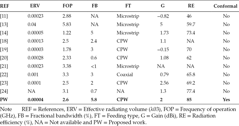
The planar CRLH 4G LTE antenna has the physical size of 20 × 20 × 0.254 mm3, which is then bent by 90° to decrease the footprint of the antenna and hence can easily be integrated on a typical smartphone. The proposed conformal 4G antenna has minimal effective radiating volume (ERV) after being bent, which is 0.00004 λ03. The proposed prototype is fabricated and respective photographs are shown in Figures 7.2(a) and 7.2(b), front and back views, respectively.
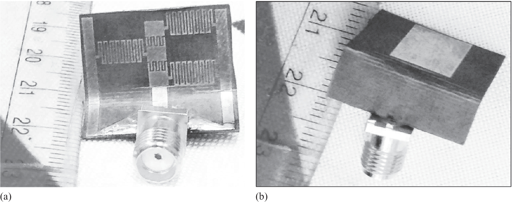
Figure 7.2
Photographs of the proposed prototype (a) Front view and (b) Back view [35].
The equivalent circuit model for the proposed CRLH-based 4G LTE antenna is depicted in Figure 7.3, in which series resistance (R) and shunt conductance (G) are also presented. The ZOR frequency depends only on the shunt parameters [14]. Thus the proposed antenna takes mainly into consideration the shunt parameters LL and CR. Also, the fractional bandwidth (BW) of the open-ended ZOR antenna is calculated by [12]:
Figure 7.3
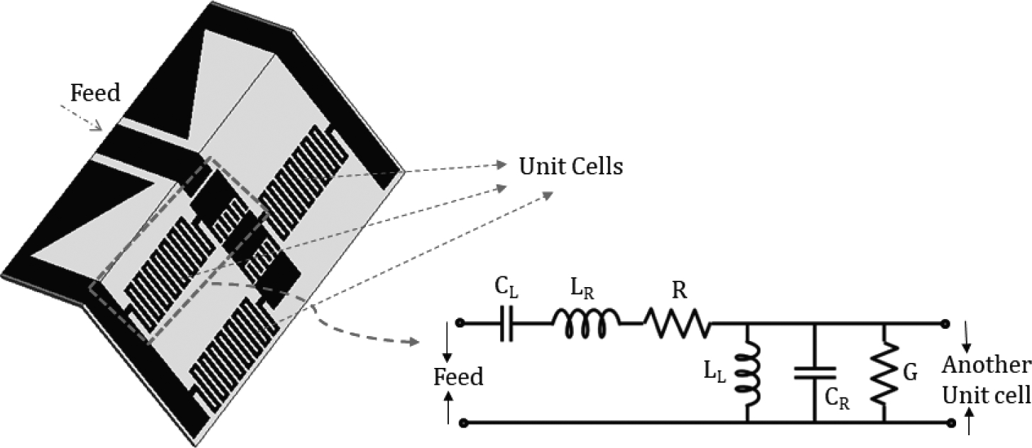
Equivalent circuit model for the CRLH unit cell of the proposed 4G LTE antenna [35].
To achieve effective miniaturization without a decrease in the fractional bandwidth of this ZOR 4G LTE antenna, only LL is increased rather than CR, which would result in the reduction of bandwidth. Since meander lines are connected in parallel, asymmetric insertion is incorporated in comparison with their symmetric counterpart, which results in an increase of LL. A localized ground behind the radiator is introduced to enhance impedance matching. Coupling capacitance (CC) is increased by placing a patch in the bottom plane, as illustrated in Figure 7.4. Thu, impedance matching can be achieved by adjusting the position and size of the bottom patch. Optimization of the equivalent circuit parameters is carried out for the desired resonance.
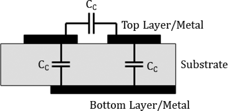
Figure 7.4
Schematics demonstrating the role of the bottom patch in impedance matching [35].
For electrically small antennas, because of low radiation resistance and high capacitive reactance, impedance matching is challenging [15]. To mitigate this effect, coplanar waveguide (CPW) feeding is introduced, which results in a decrease in capacitive reactance by reducing the cross-section area between the trace and the ground. In addition, a high impedance transformer line is introduced, which results in an increase in radiation resistance. CPW feeding is also introduced because of the flexibility of enhancing LL by inserting a number of meander lines. Also, because of the higher separation between the CPW ground and the radiation patches, the CR parameter is reduced, which contradicts the microstrip feeding technique. A microstrip-fed structure is not the optimal choice to achieve miniaturization in ZOR antennas, since parameters LL and CR cannot be controlled in such a structure by the geometry of the metal trace. Shorting pins could be used for miniaturization but they would lead to complexity in fabrication with narrow bandwidths.
According to standard CPW calculations [16], the characteristic impedance of the feed line in the proposed antenna is 50 Ω. The CPW ground is tapered in order to increase the impedance bandwidth (BW). Also, the CPW-fed antenna will result in the least number of discontinuities after conforming by 90°, compared to the microstrip feeding, because the latter has a copper plane on the ground which will also be at maximum strain, thus causing impedance mismatch [17].
The simulated and measured input reflection coefficient (|S11|) of the 4G LTE planar as well as of the conformal antenna is shown in Figure 7.5. The measured results were carried out using the Agilent PNA E8364C vector network analyser. The conformal 4G LTE antenna covers class 7 LTE band. The measured impedance bandwidth of the proposed conformal 4G LTE antenna is from 2.5 to 2.65 GHz, with the fractional bandwidth of the proposed antenna being about 5.8%, which is greater than the other designs as listed in Table 7.1. For the conformal miniaturized antenna, reduction of impedance bandwidth can be seen from planar to conformal geometry. This is because of the discontinuity that occurs in the antenna while making a 90° bend. The disparity can be observed in the simulated and measured data, which may be a result of manufacturing tolerances. Also, the frequency shift may be caused by the inhomogeneous dielectric constant of the substrate [13].
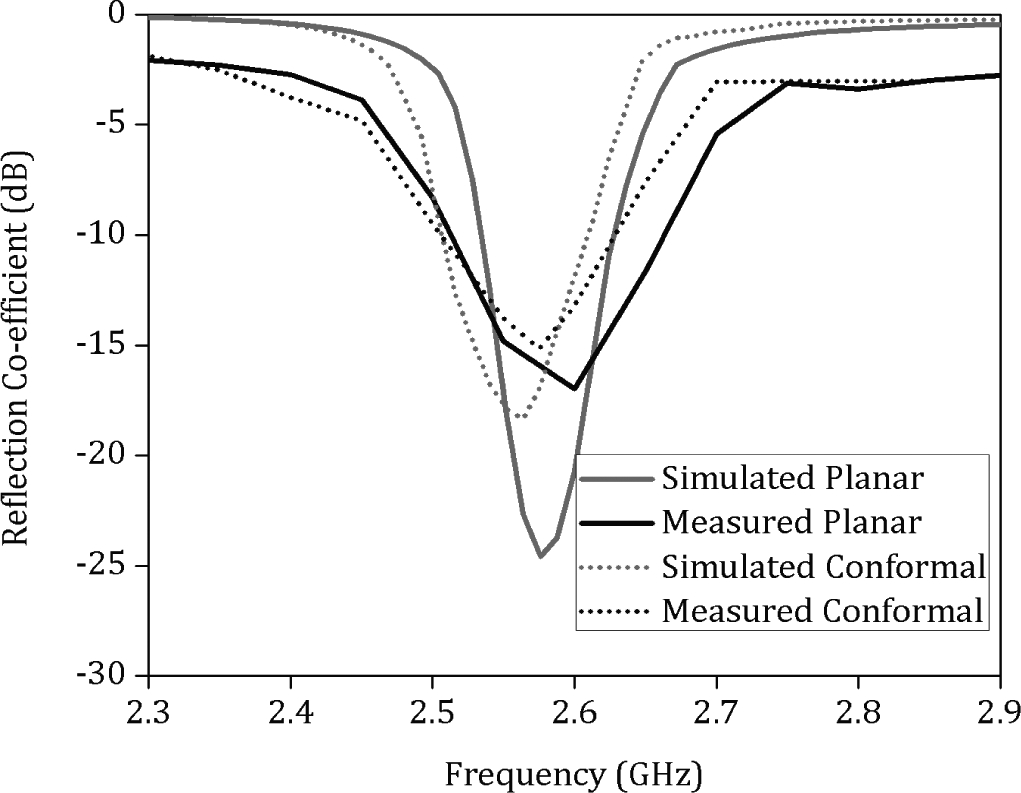
Figure 7.5
Input reflection co-efficient of the 4G LTE antenna [35].
Table 7.1
Comparison of the Proposed 4G Antenna with Reported Articles
The simulated and measured radiation patterns in both the principal planes of the proposed 4G LTE antenna are illustrated in Figure 7.6 at 2.6 GHz. The measured results were carried out in an anechoic chamber. As can be seen from the figure, the conformal antenna achieves the omnidirectional radiation pattern. Discrepancies between the simulated and measured results are because of the poor absorptivity of oblique incidence in the anechoic chamber. The measured cross-polarization radiation patterns in both the planes are 25 dB less than the co-polarization radiation pattern, indicating strongly linearly polarized antenna.
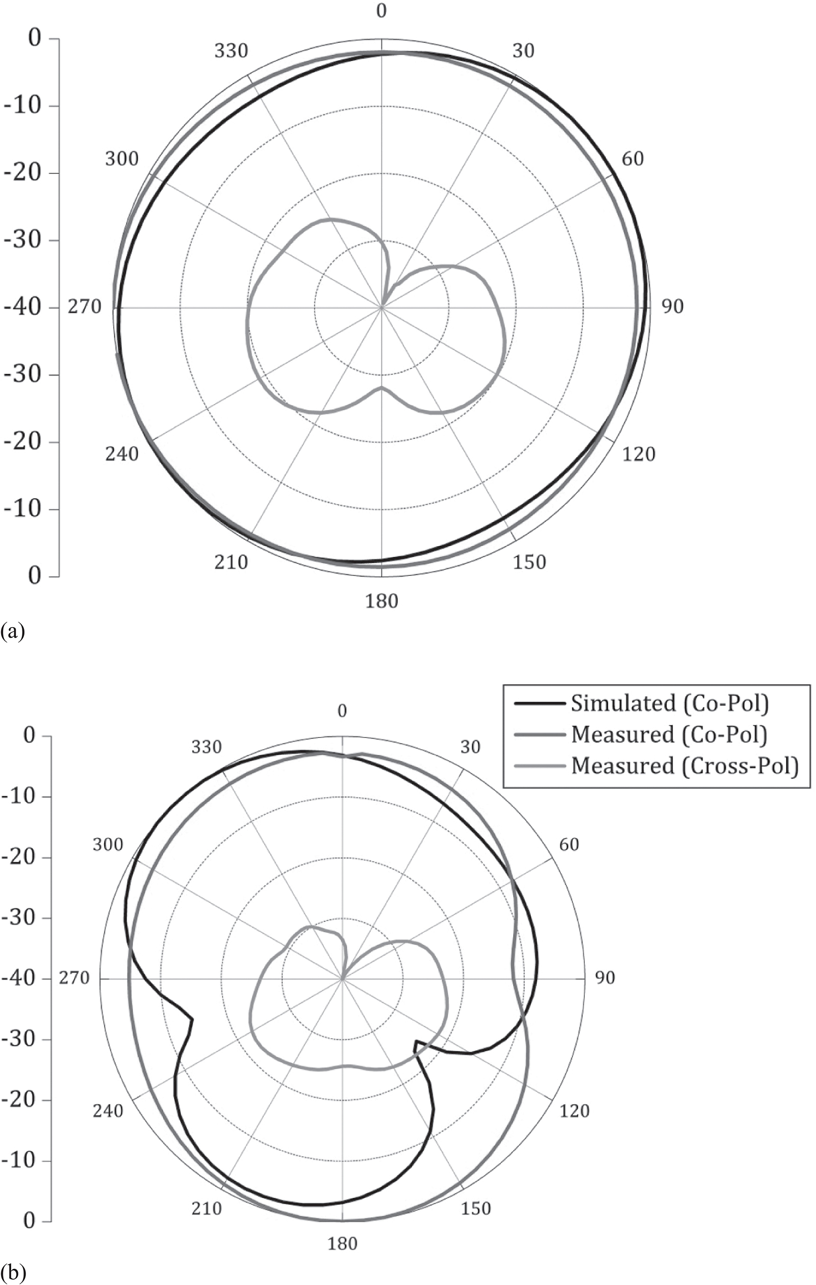
Figure 7.6
Simulated and measured far-field radiation patterns in (a) YZ plane and (b) XY plane at 2.6 GHz [35].
The simulated and measured realized gain of the proposed antenna varies within the operating band 1.6 to 2.2 dBi, which indicates a high gain yield for the electrical size of the proposed antenna. The simulated radiation efficiency of the proposed 4G LTE antenna has the range within 75%–90%, which is caused by the utilization of electrically thin substrate. Realized gain and radiation efficiency plots are collectively shown in Figure 7.7.
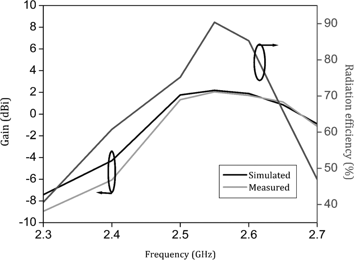
Figure 7.7
Peak gain and radiation efficiency of the proposed antenna [35].
7.3.2Compact CRLH-Based Conformal 4G LTE MIMO Antenna
The proposed 4G LTE MIMO antenna system consists of electrically close two-CRLH-based conformal antennas. The two conformal antennas, which are separated by a distance of 0.3 λ0 can easily be placed along the edge of a typical smartphone. A photograph of the fabricated prototype with isometric view is depicted in Figure 7.8.
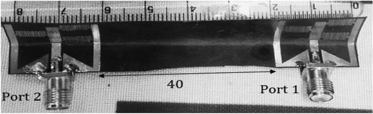
Figure 7.8
Photograph of the proposed 4G LTE MIMO antenna [35].
The simulated and measured isolation between two elements of the proposed 4G LTE MIMO is more than 15 dB across the whole operating band, as shown in Figure 7.9(a). Discrepancies between the simulated and measured results can be observed, which result from fabrication tolerances, substrate inhomogeneity and connector modelling. The three-dimensional (3D) realized gain of two-element proposed MIMO antenna at 2.6 GHz is shown in Figure 7.9(b). The beam tilt is observed as a result of the electrical offset of antennas with respect to the phase centre.
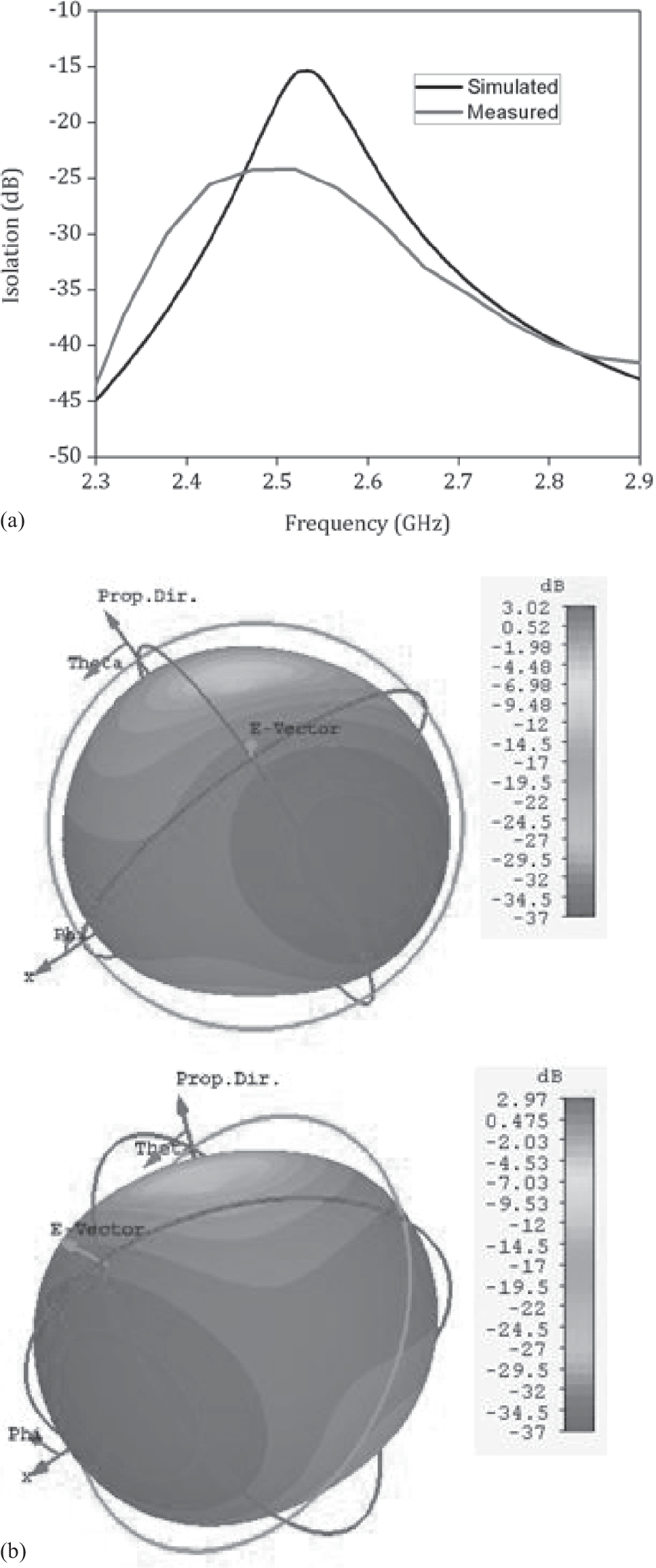
Figure 7.9
Isolation between the ports for 4G LTE (b) 3D radiation patterns for 4G LTE [35].
For MIMO antennas, the Envelope Correlation Coefficient (ECC) is an important performance metric. The ECC should be minimal for the optimal performance of the antenna module. The ECC of the proposed 4G LTE MIMO antenna module is less than 0.04, as shown in Figure 7.10, which is minimal.

Figure 7.10
ECC of the proposed CRLH-based 4G LTE MIMO antenna [35].
7.4Conformal mmWave 5G MIMO Antenna
Typical phased array designs would suffer from scanning loss when the beam is tilted away from the boresight, hence it is not feasible to design a phased array system which works at both 0° and 90°. In order to accommodate both the landscape and portrait modes, the conformal antennas are placed orthogonally at the edge of the smartphone, and beam switching could be performed when the user orients the smartphone in either landscape or portrait mode. Since the conformal antennas are placed orthogonally, the gain and the pattern integrity is maintained in either of the modes.
The proposed conformal antenna operating at 28 GHz is depicted in Figure 7.11. Its corresponding input reflection coefficient and the forward gains are depicted in Figure 7.12, followed by its radiation patterns in Figure 7.13. The antenna is a standard inset-fed microstrip patch design on Nelco NY9220 with εr of 2.2 and a loss tangent of 0.0009. The loss tangent plays a crucial role in the gain yield of the antenna, especially at 28 GHz. The flexible design of [7] has a loss tangent of 0.022 which reduces the gain by 2 dB. The antenna is conformed to a 90° bend, to fit into a typical mobile terminal.
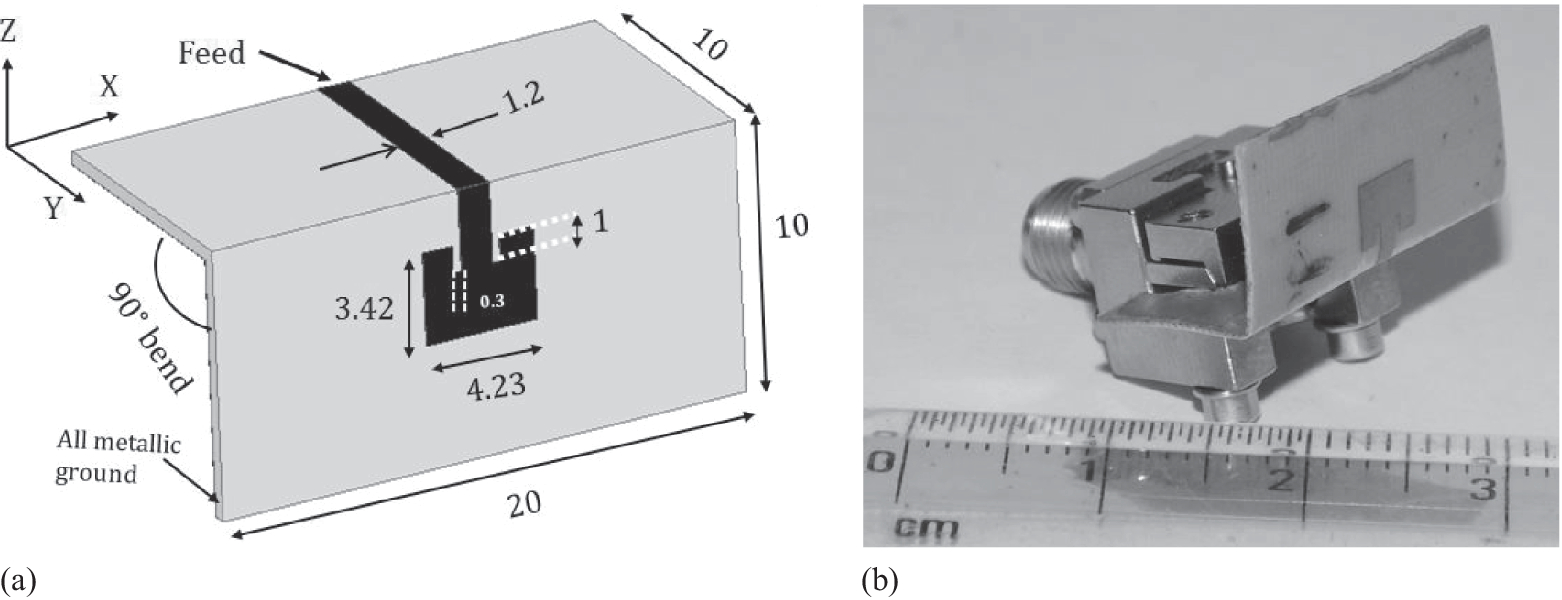
Figure 7.11
(a) Schematic and (b) Photograph of the proposed antenna [35].
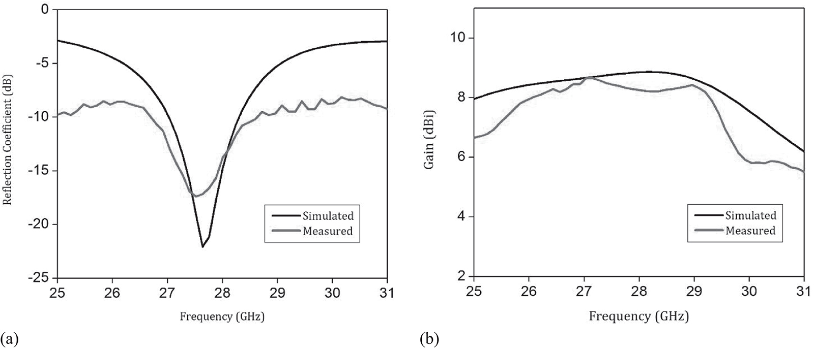
Figure 7.12
(a) Reflection coefficient and (b) Forward gain of the 5G antenna [35].
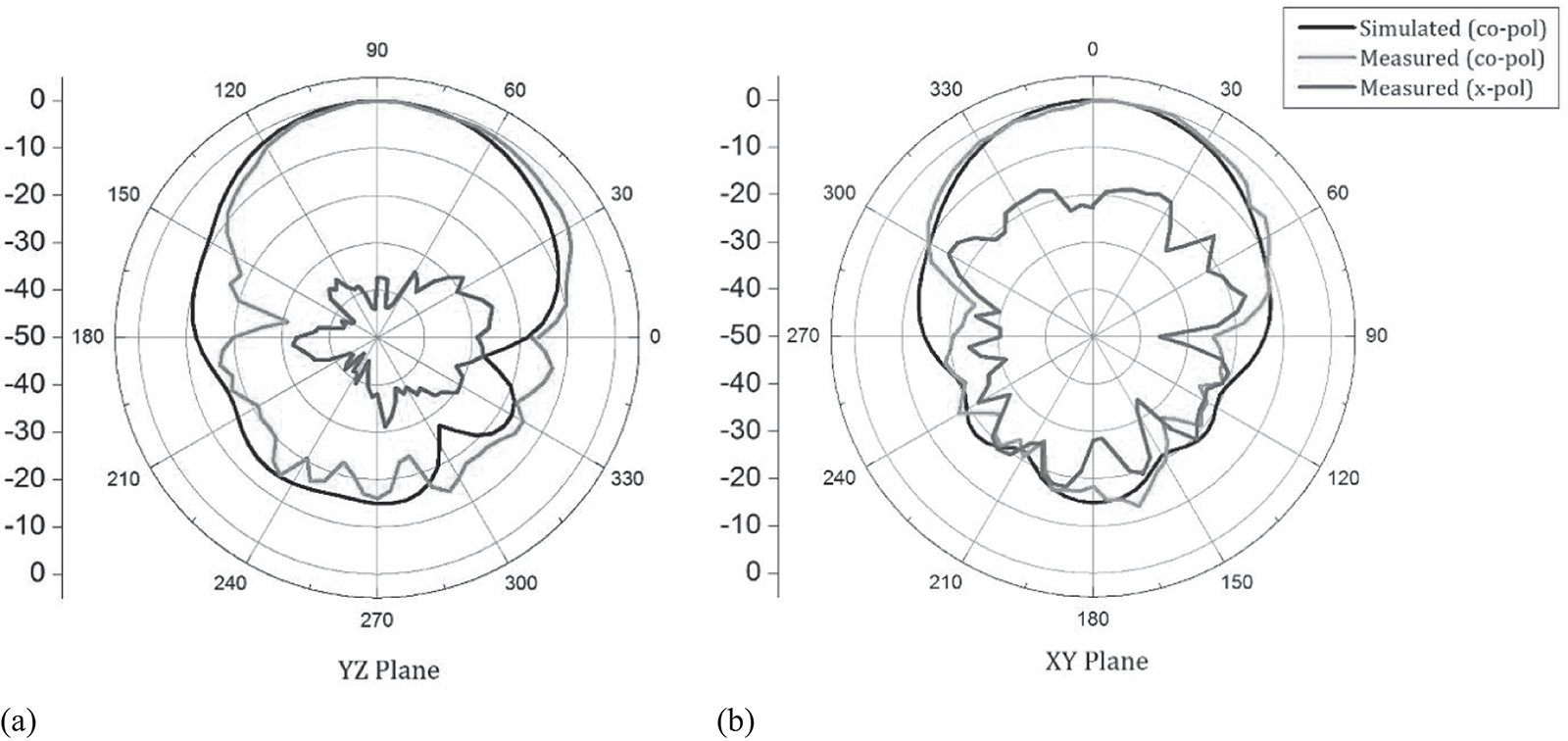
Figure 7.13
Patterns in (a) YZ plane and (b) XY plane at 28 GHz [35].
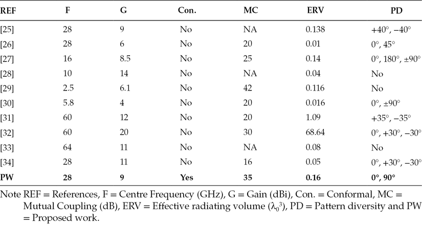
Orthogonal conformal pattern diversity is also proposed, as seen in Figure 7.14. Because of the orthogonal topology of the mmWave 5G antennas in MIMO configuration, isolation of less than 40 dB is achieved in the whole operating band, as shown in Figure 7.15. Also, ECC is less than 0.00001, as depicted in Figure 7.16, which is very low. It is evident from Table 7.2 that the proposed architecture yields high gain with orthogonal pattern diversity with minimal footprint.
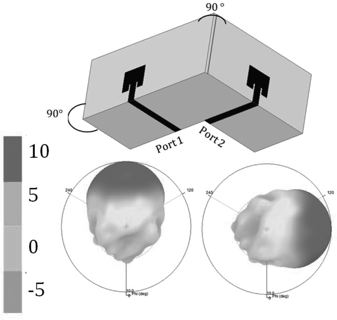
Figure 7.14
Orthogonal pattern diversity architecture and its 3D patterns at 28 GHz [35].
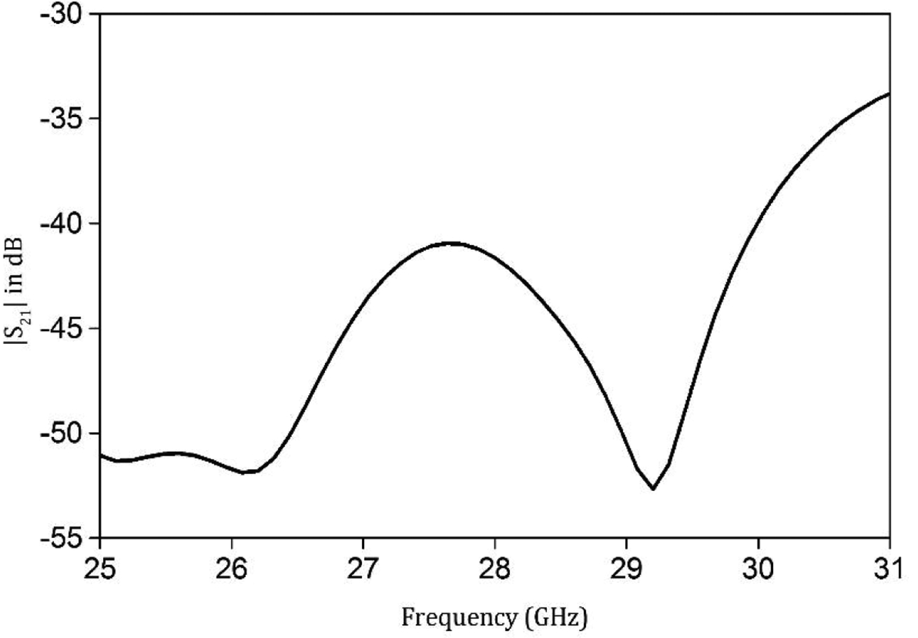
Figure 7.15
Isolation plot of the proposed mmWave 5G MIMO antenna [35].
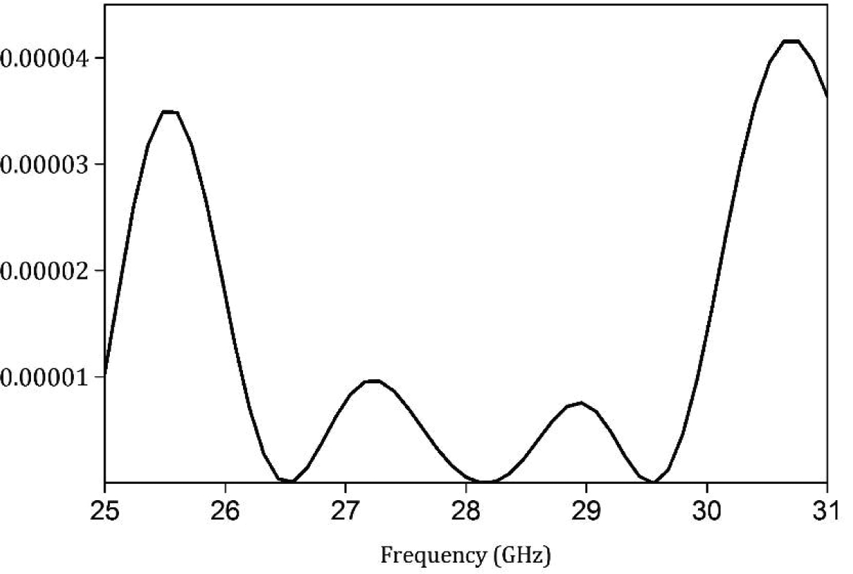
Figure 7.16
ECC of the proposed mmWave 5G MIMO antenna [35].
Table 7.2
Comparison of mmWave 5G MIMO with other Reported Articles
7.5Corner Bent Integrated Design of 4G LTE and mmWave 5G Antennas
Antenna designs and simulations are carried out in computer simulation technology (CST) Microwave Studio (MS). Proposed 4G LTE and mmWave 5G MIMO antenna architecture is designed on 10-mil-thick Rogers 5870 substrate with dielectric constant (εr) of 2.33 ± 0.02 and loss tangent of 0.0012. Substrate of low relative permittivity was chosen in order to minimize surface wave modes. In addition, the low radiation efficiency is also the consequence of using the substrate of high dielectric constant and high loss tangent; 10-mil substrate is used as it is the optimal choice for achieving corner bending. Thin substrate was chosen in order to decrease cross polarization; 5-mil substrate is more flexible than the proposed substrate but requires additional scaffolding. Flexible substrates such as polyethylene terephthalate (PET) and polycarbonate have a high dielectric loss tangent, which will result in additional gain deterioration at mmWave frequencies.
7.5.14G LTE Antenna Design
Schematics of the proposed 4G LTE antenna integrated with mmWave 5G antenna module is depicted in Figures 7.17(a) and 7.17(b), with top and bottom planes, respectively. The proposed 4G LTE section of the antenna is electrically small, having the dimensions of 0.08 λ × 0.17 λ × 0.001 λ at 1.7 GHz. A rectangular slot of proper dimensions is etched on the ground plane, which is excited by a 50 Ω microstrip line on the other plane. The proposed slot antenna achieves resonance depending on the relative position of the microstrip feed, the width of the rectangular slot and the length of the feed line. The proposed antenna is optimized against these parameters, and the dimensions are given in Figure 7.17.
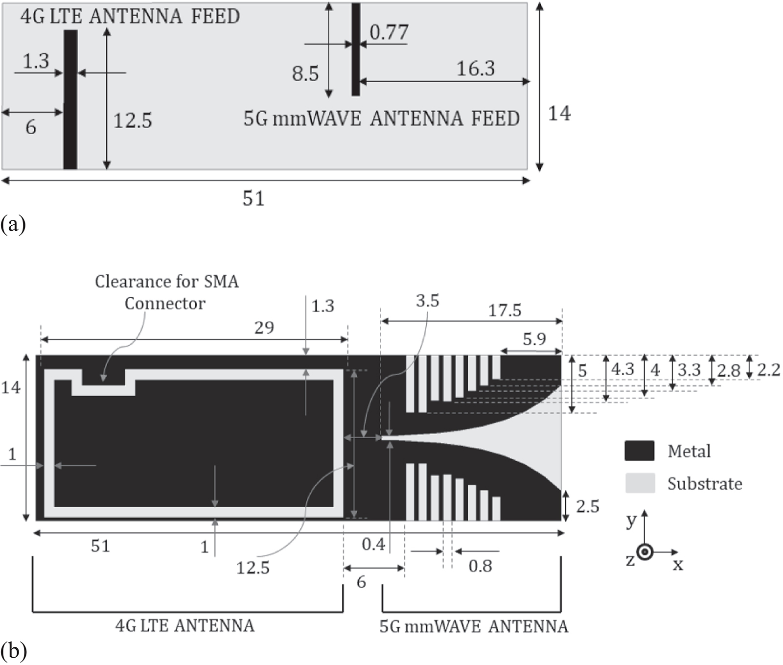
Figure 7.17
Schematics of the proposed integrated 4G LTE and mmWave 5G antenna (a) Top plane and (b) Bottom plane (all dimensions are in mm) [36].
The proposed co-designed 4G LTE and mmWave 5G antenna is fabricated and the photograph is shown in Figures 7.18(a) and 7.18(b), with top and bottom planes, respectively. The simulated and measured input reflection coefficient of the proposed 4G LTE antenna is illustrated in Figure 7.19(a). Measured results were carried out using Agilent PNA E8364C. The measured impedance bandwidth of the proposed 4G LTE antenna is from 1.7 to 3 GHz. The proposed antenna is wideband, having a fractional bandwidth of 55%. The proposed prototype covers multiple LTE bands such as LTE1700 (1710–2170 MHz), LTE2300 (2300–2400 MHz) and LTE2500 (2500–2690 MHz), thus making carrier aggregation possible for achieving higher data rates. Discrepancies between simulated and measured data may be related to fabrication tolerances. Also, frequency shift may be caused by the inhomogeneity of the relative permittivity of the substrate.
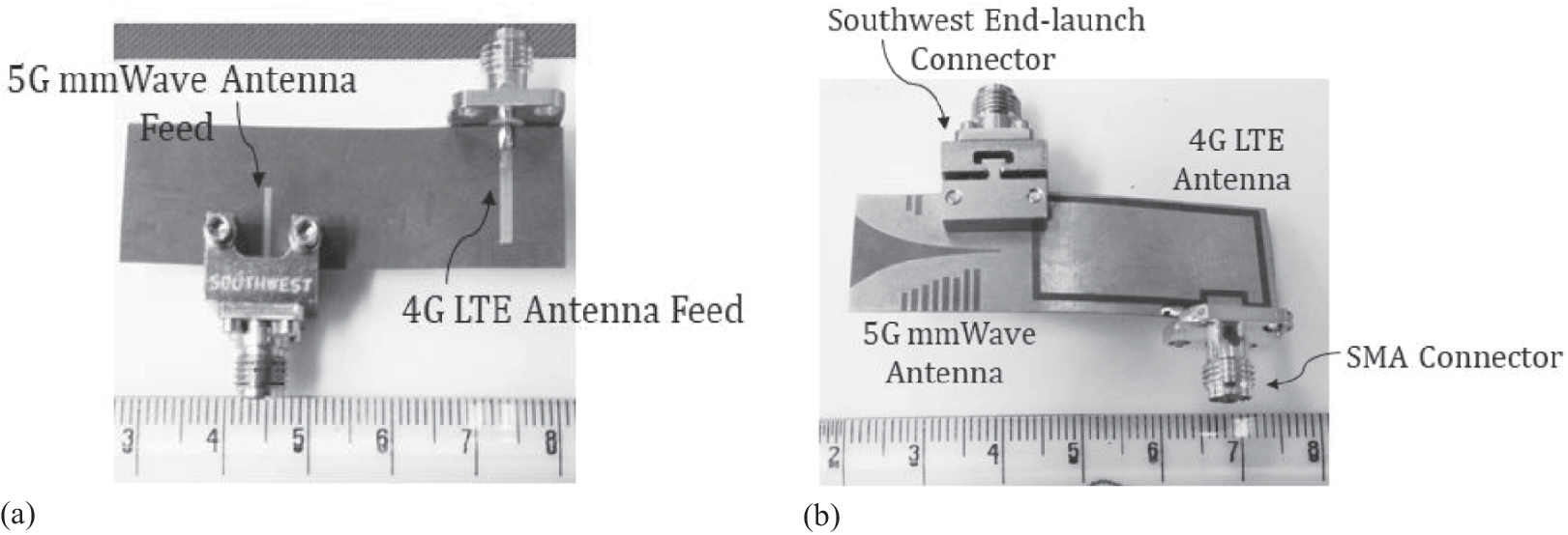
Figure 7.18
Photograph of the fabricated co-designed 4G LTE and mmWave 5G antenna (a) Top plane and (b) Ground plane [36].
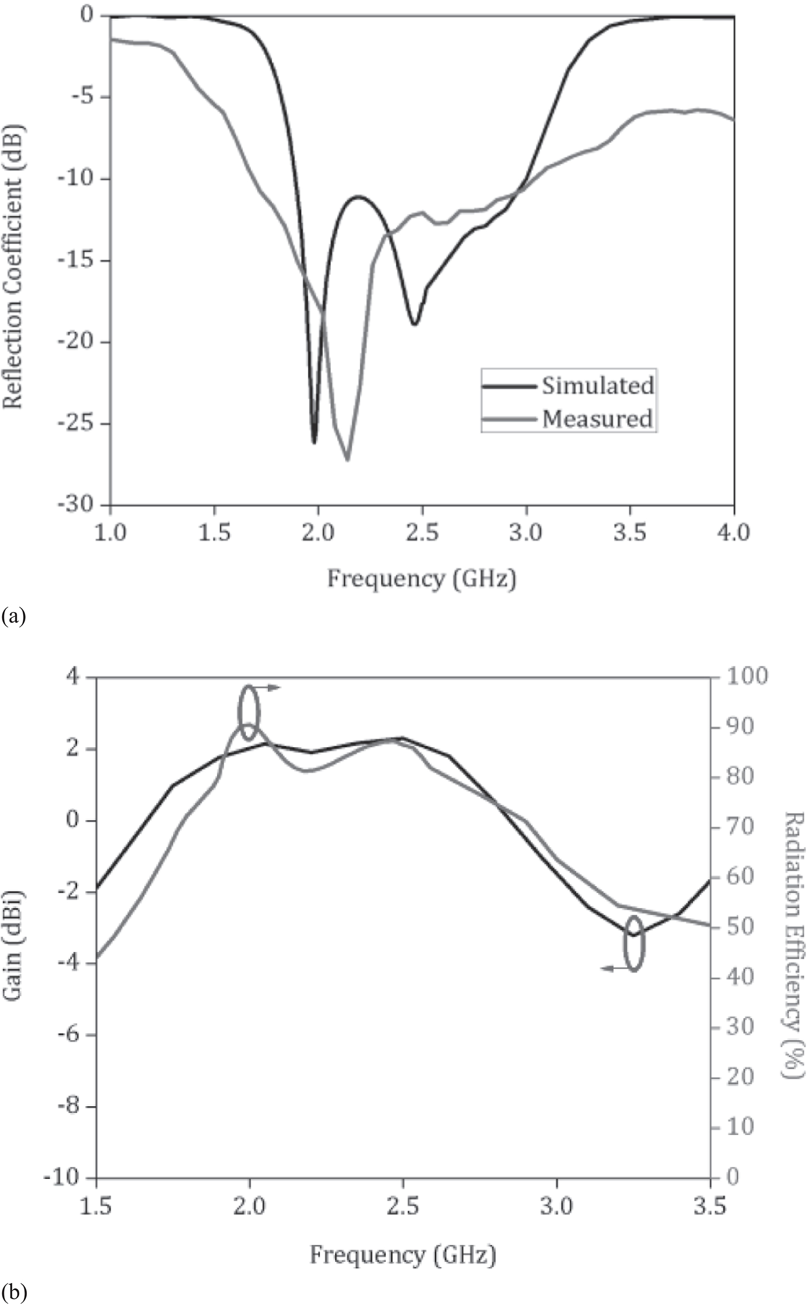
Figure 7.19
(a) Input reflection co-efficient and (b) Gain and radiation efficiency plots of the proposed 4G LTE antenna [36].
The broadside gain and radiation efficiency plot of the proposed antenna are depicted in Figure 7.19(b). Gain of the proposed antenna at the operating LTE bands lies between 1.7 and 2.1 dBi, indicating high gain yield for the given electrical size. In addition to this, radiation efficiency at the LTE bands lies between 60% and 85%. The high efficiency of the proposed antenna is a result of the electrically thin substrate with a low dissipation factor. Simulated and measured radiation patterns of the proposed antenna in the YZ-plane (E-plane) are illustrated in Figures 7.20(a),7.20(b) and 7.20(c). Measured results were carried out in an anechoic chamber. The proposed antenna achieves pattern integrity with dipole-like radiation patterns. Disparity between simulated and measured data results from poor absorptivity of the oblique incidence in the anechoic chamber.
Figure 7.20
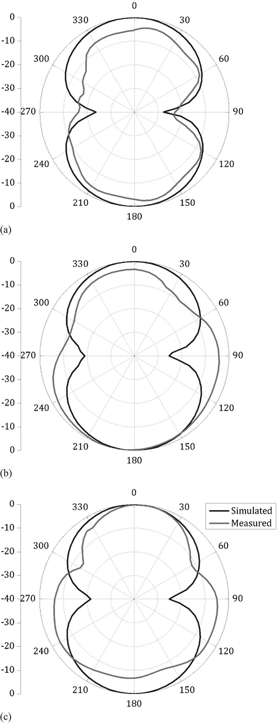
Simulated and measured radiation plots in the YZ-plane at (a) 1.8 GHz, (b) 2.3 GHz and (c) 2.6 GHz [36].
7.5.2mmWave 5G Antenna Design
A tapered slot antenna with end-fire gain is designed for mmWave 5G applications. Schematics of the proposed mmWave 5G antenna co-designed with 4G LTE antenna are shown in Figures 7.17(a) and 7.17(b), with top and ground planes, respectively. The proposed mmWave 5G section of the antenna has the dimensions of 1.75 λ × 1.4 λ × 0.0254 λ at 28 GHz. The tapered slot antenna is a travelling wave antenna, a 50 Ω microstrip line is feeding the balun of a Vivaldi antenna, and microstrip to slot line transition is optimized for better impedance matching. The proposed antenna tapers exponentially in the ground plane. The antenna starts to radiate from the metallic taper until the electromagnetic wave has travelled around half of the wavelength. Corrugations are inserted in the proposed antenna to concentrate the E-field towards the main radiating aperture, thereby reducing back lobe. Thus cross polarization and side-lobe levels for the proposed antenna are reduced.
Photographs of the proposed mmWave 5G antenna are shown in Figures 7.18(a) and 7.18(b), with top and bottom planes, respectively. The simulated and measured input reflection coefficient of the proposed antenna is illustrated in Figure 7.21(a). The measured impedance bandwidth is high, ranging from 25 to 38 GHz with a fractional bandwidth of 41%. Discrepancies can be imputed to fabrication tolerances and deviation in port impedance offered by the end-launch connector. Gain of the proposed antenna lies between 9 and 10.5 dBi, indicating high gain for the available aperture, as depicted in Figure 7.21(b). Moreover, a 1-dB gain bandwidth of the proposed antenna is around 28%, with gain varying between 9.5 and 10.5 dBi. Standard gain transfer method is used for gain measurement using Keysight horn antennas. As path loss is high at mmWave frequencies, mobile phone antennas must possess high gain. Also, efficiency for the proposed antenna is high ranging between 80% and 88% as shown in Figure 7.21b.
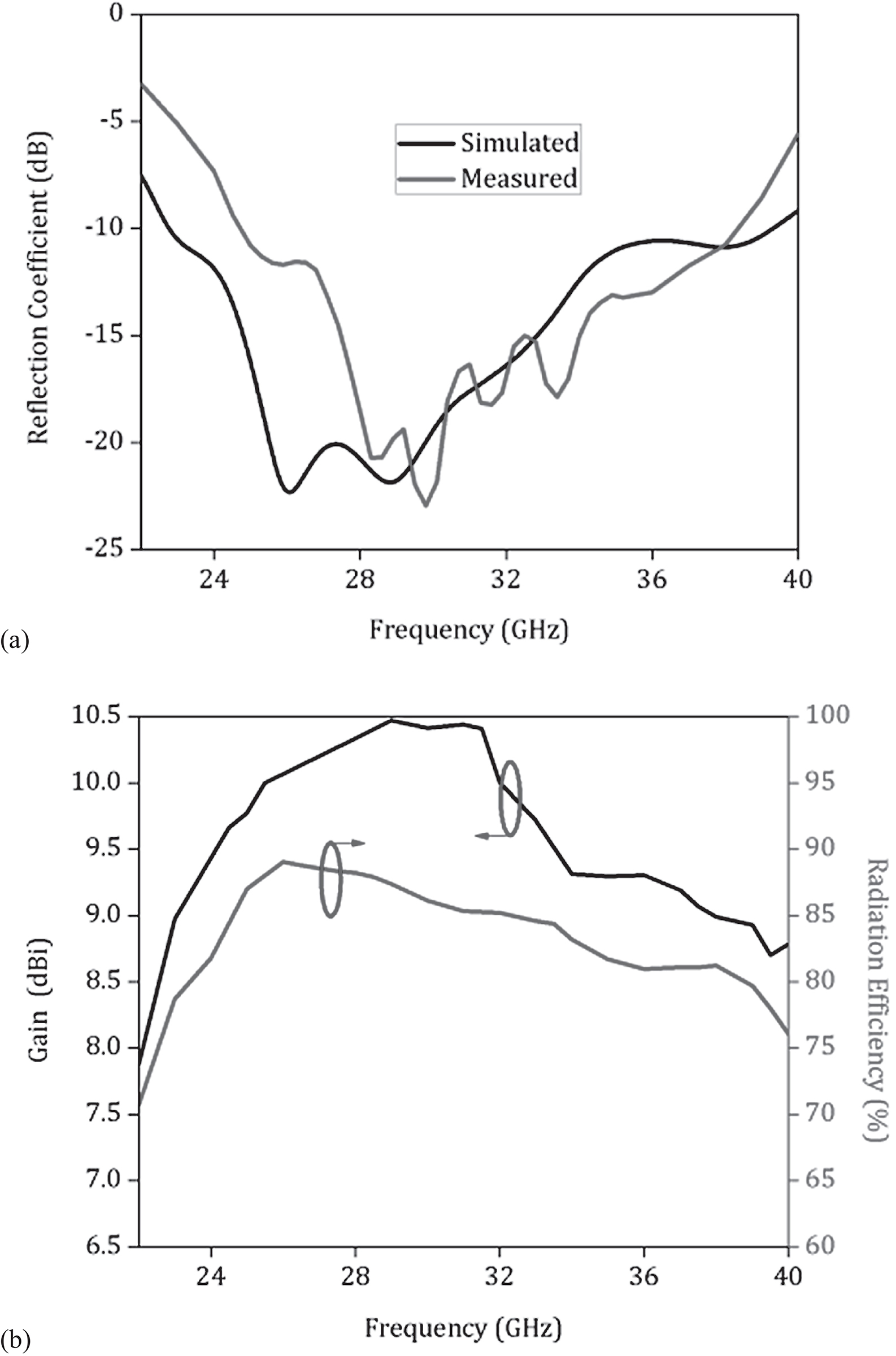
Figure 7.21
(a) Input reflection coefficient and (b) Gain and radiation efficiency plots of the proposed mmWave 5G antenna [36].
The travelling wave phenomenon is realized as illustrated in Figure 7.22 with the travelling wave propagating at two different time instants. Simulated and measured radiation patterns of the proposed mmWave 5G antenna in the XY-plane at 28, 33 and 38 GHz are depicted in Figures 7.23(a),7.23(b) and 7.23(c). The proposed antenna shows pattern integrity at all of the three given frequencies. The front-to-back ratio of the proposed tapered slot antenna is greater than 15 dB. Disparity between simulated and measured patterns is caused by alignment errors and the adapters used for pattern measurement.
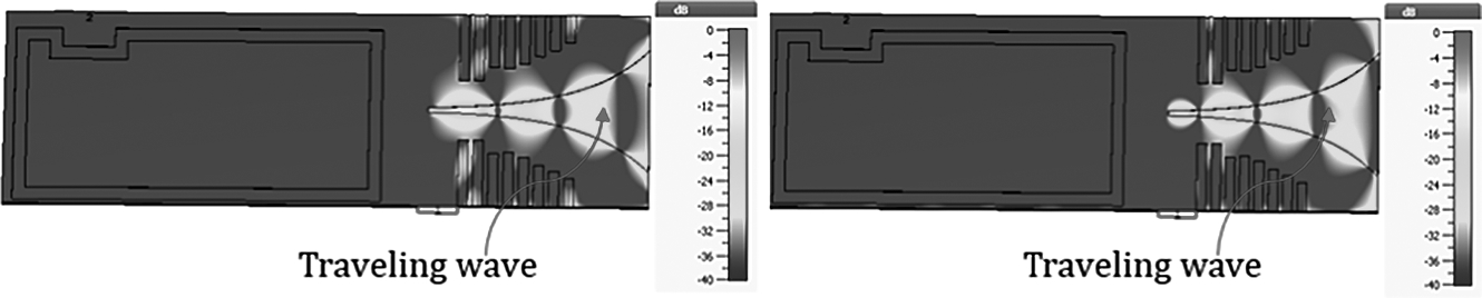
Figure 7.22
E-field plots for the proposed mmWave 5G antenna at (a) t = 0 and (b) t = T/4 [36].
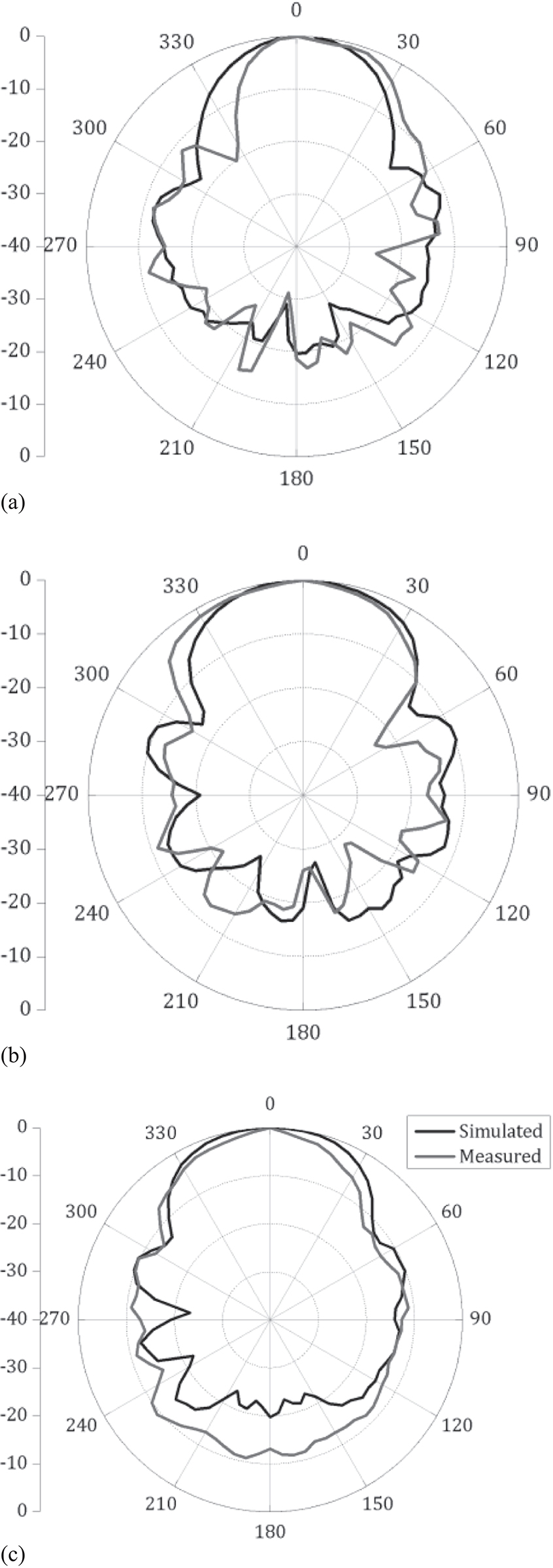
Figure 7.23
Simulated and measured radiation plots in XY-plane at (a) 28 GHz, (b) 33 GHz and (c) 38 GHz [36].
7.5.3Co-Designed Corner Bent 4G LTE and mmWave 5G MIMO Antennas
The proposed 4G LTE and mmWave 5G antennas are integrated with each other on the same 10-mil Rogers 5870 substrate and separated by a distance of 3.5 mm. Corner bending is carried out to decrease the effective radiating volume. It is also done to fit the antenna into the corner of a typical smartphone. The antenna’s characteristics were observed and there was no significant variation in the input reflection coefficient or gain of either the 4G LTE or the mmWave 5G antenna.
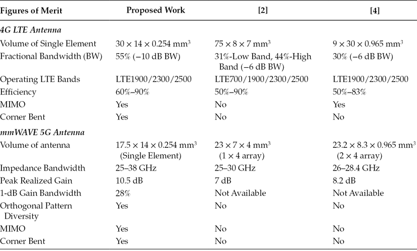
For realizing a corner bent MIMO configuration, another co-designed 4G LTE and mmWave element is brought to the opposite corner of a smartphone, as illustrated in Figure 7.24. Moreover, isolation between the closely spaced integrated 4G LTE and mmWave 5G antennas is less than 30 dB, as shown in Figure 7.25(a). The two antenna elements are placed in such a way that orthogonal pattern diversity at mmWave frequencies is achieved, as depicted in Figure 7.25(b). Orthogonal pattern diversity results in the usage of a mobile phone in portrait as well as landscape mode. Table 7.3 illustrates the comparison between proposed 4G LTE and mmWave corner bent MIMO antenna design with other reported designs.
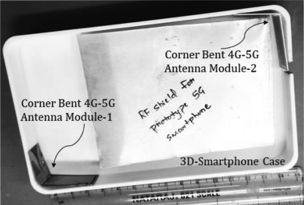
Figure 7.24
Integrated 4G LTE and mmWave 5G corner bent MIMO antenna design inside a typical mobile phone case [36].
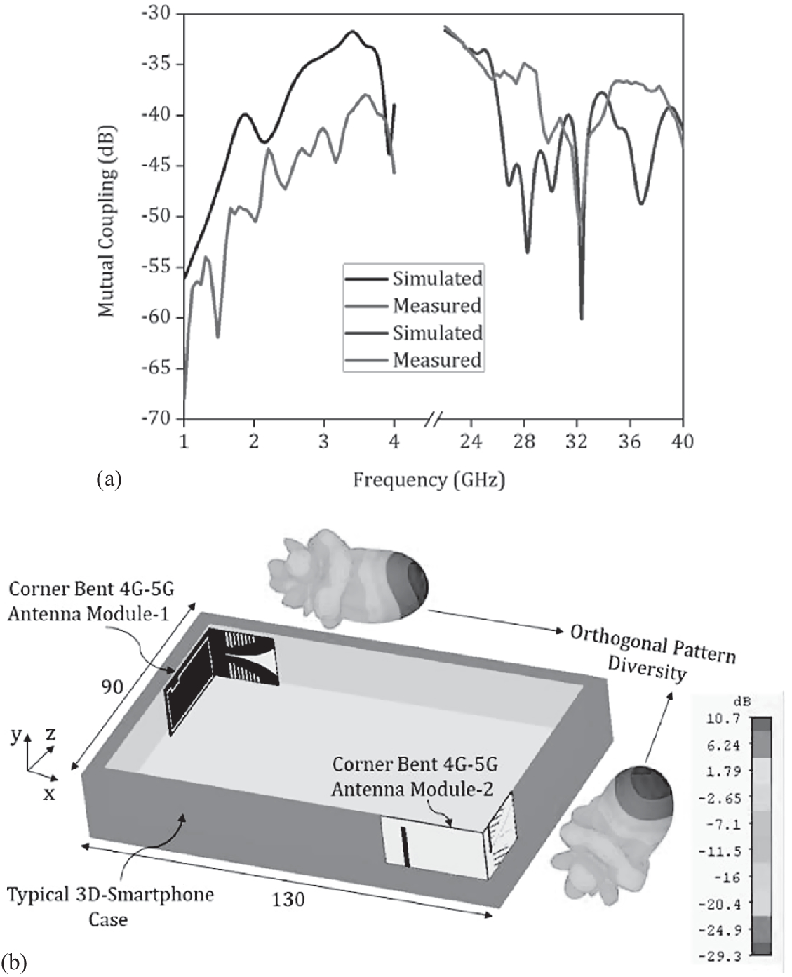
Figure 7.25
(a) Isolation plot of the co-designed 4G LTE and mmWave antenna element and (b) Orthogonal pattern diversity architecture with 3D patterns at 28 GHz [36].
Table 7.3
Comparison of the Proposed MIMO Antenna Design with other Reported Designs
7.6Case Study: Co-Design of 4G and 5G Antennas in a Smartphone
The proposed antennas reported in Sections 7.3 and 7.4 are integrated to investigate their characteristics. The schematics of the proposed integrated antenna system are shown in Figure 7.26.
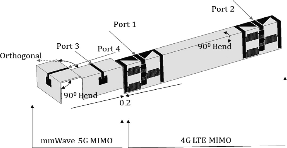
Figure 7.26
Schematics of integrated 4G LTE MIMO and mmWave 5G MIMO antenna [36].
The 4G LTE and mmWave 5G MIMO antennas are brought close to each other, separated by a distance of 0.2 mm. The antennas’ characteristics were observed and there was no significant effect on the reflection coefficient or gain of either the 4G LTE or the mmWave 5G MIMO antenna. Further, isolation is less than 40 dB (|S31| or |S13|) between two closely spaced 4G LTE/mmWave 5G antennas and less than 55 dB between the distant 4G/5G antennas. In order to illustrate the operation of the proposed co-design, a real-world deployment was performed, as can be seen from FigureS 7.27 (a) and 7.27(b).
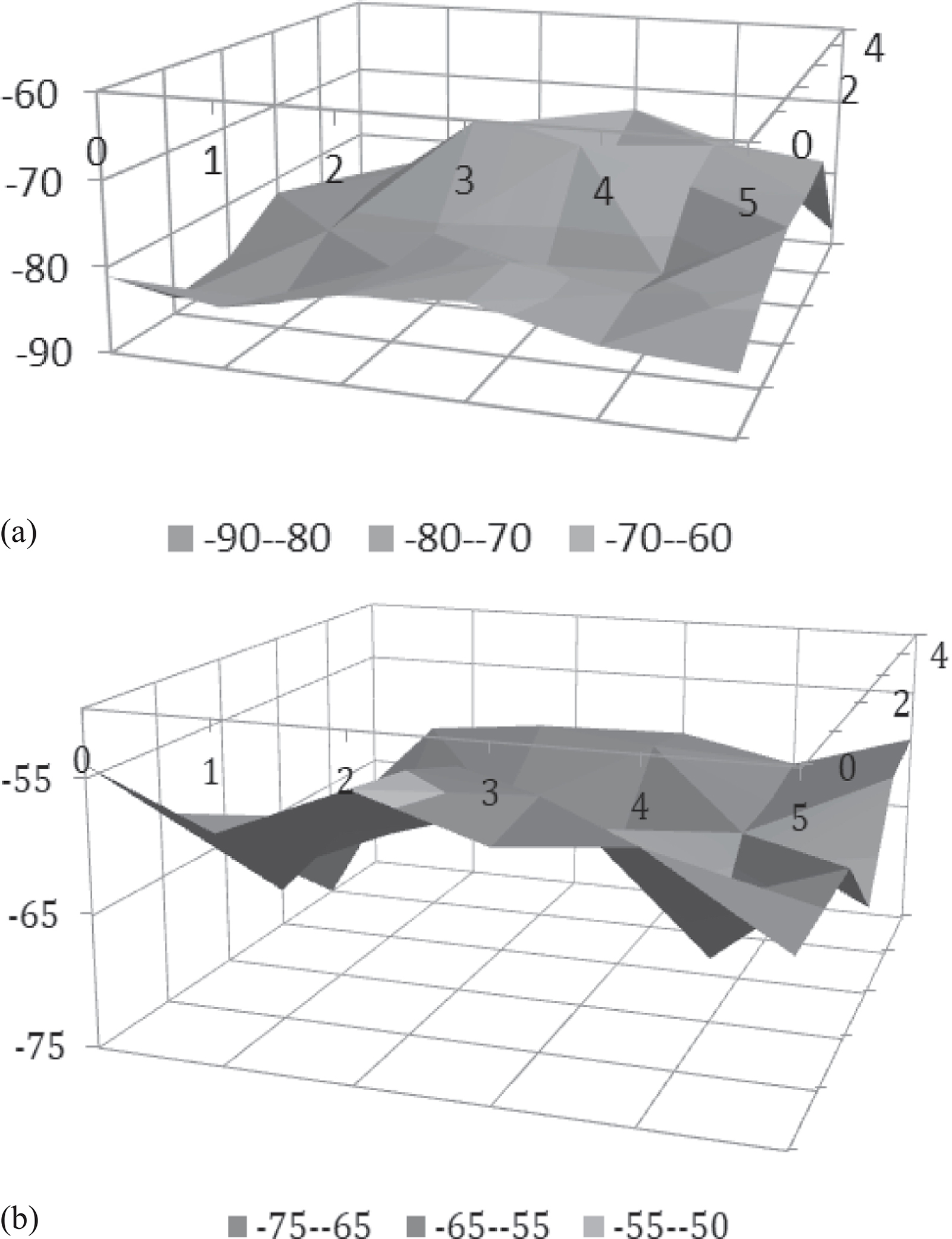
Figure 7.27
Received power profile for (a) 5G and (b) 4G [36].
7.7Conclusion
In this chapter, a compact conformal integrated design for 4G LTE and mmWave 5G antennas has been proposed. The 4G LTE MIMO antenna system consists of two CRLH-based CPW-fed conformal antennas which relate to the class-7 4G LTE band. The proposed antenna is designed on a 10 mil thin substrate with electrically small dimensions of 20 × 20 mm2. For the mmWave 5G MIMO antenna system, conformal orthogonally placed microstrip-fed antennas are proposed. The conformal mmWave 5G antenna system operates at 28 GHz with a forward gain of 9 dBi. 4G LTE and 5G mmWave MIMO antennas are integrated electrically close by 0.004λ to achieve minimal physical footprint. Real-world deployment was performed for both the 4G LTE and the mmWave 5G MIMO antenna systems. All the results validate that the proposed co-design is a good candidate for mobile terminals.
References
- 1.J. Lu and Y. Wang, “Planar small-size eight-band LTE/WWAN monopole antenna for tablet computers,” IEEE Transactions on Antennas and Propagation, 62(8), 4372–4377, August 2014.
- 2.J. Kurvinen, H. Kähkönen, A. Lehtovuori, J. Ala-Laurinaho, and V. Viikari, “Co-designed mm-wave and LTE handset antennas,” IEEE Transactions on Antennas and Propagation, 67(3), 1545–1553, March 2019.
- 3.M. S. Sharawi, M. Ikram, and A. Shamim, “A two concentric slot loop based connected array MIMO antenna system for 4G/5G terminals,” IEEE Transactions on Antennas and Propagation, 65(12), 6679–6686, December 2017.
- 4.R. Hussain, A. T. Alreshaid, S. K. Podilchak, and M. S. Sharawi, “Compact 4G MIMO antenna integrated with a 5G array for current and future mobile handsets,” IET Microwave Antennas Propagation, 11(2), 271–279, February 2017.
- 5.D. J. Chung, S. K. Bhattacharya, G. E. Ponchak, and J. Papapolymerou, “An 8×8 lightweight flexible multilayer antenna array,” 2009 IEEE Antennas and Propagation Society International Symposium, Charleston, SC, 1–4, 2009.
- 6.M.S. Sharawi, Printed MIMO Antenna Engineering, Norwood, MA, USA: Artech House, 2014.
- 7.S. F. Jilani and A. Alomainy, “Planar millimeter-wave antenna on low-cost flexible PET substrate for 5G applications,” 2016 10th European Conference on Antennas and Propagation (EuCAP), Davos, 1–3, 2016.
- 8.K. Sarabandi, J. Oh, L. Pierce, K. Shivakumar, and S. Lingaiah, “Lightweight, conformal antennas for robotic flapping flyers,” IEEE Antennas and Propagation Magazine, 56(6), 29–40, December 2014
- 9.H. Wong, K. K. So, K. B. Ng, K. M. Luk, C. H. Chan, and Q. Xue, “Virtually shorted patch antenna for circular polarization,” IEEE Antennas and Wireless Propagation Letters, 9, 1213–1216, 2010.
- 10.D. Wang, H. Wong, and C. H. Chan, “Small patch antennas incorporated with a substrate integrated irregular ground,” IEEE Transactions on Antennas and Propagation, 60(7), 3096–3103, July 2012
- 11.N. Amani and A. Jafargholi, “Zeroth-order and TM10 modes in one-unit cell CRLH mushroom resonator,” Antennas and Wireless Propagation Letters IEEE, 14, 1396–1399, 2015
- 12.V. Rajasekhar Nuthakki and S. Dhamodharan, “Via-less CRLH-TL unit cells loaded compact and bandwidth-enhanced metamaterial based antennas,” AEU – International Journal of Electronics and Communications, 80, 48–58, 2017.
- 13.C. Zhang, J. Gong, Y. Li, and Y. Wang, “Zeroth-order-mode circular microstrip antenna with patch-like radiation pattern,” Antennas and Wireless Propagation Letters IEEE, 17(3), 446–449, 2018.
- 14.S. K. Sharma and R. K. Chaudhary, “A compact zeroth-order resonating wideband antenna with dual-band characteristics,” IEEE Antennas and Wireless Propagation Letters, 14, 1670–1672, 2015
- 15.L. Si, W. Zhu, and H. Sun, “A compact, planar, and CPW-fed metamaterial-inspired dual-band antenna,” IEEE Antennas and Wireless Propagation Letters, 12, 305–308, 2013
- 16.B. Bharathi and S. K. Koul, “Stripline-Like Transmission Lines for Microwave Integrated Circuits. New York: Wiley, 1989.
- 17.G. S. Karthikeya, M. P. Abegaonkar, and S. K. Koul, “CPW fed wideband corner bent antenna for 5G mobile terminals,” IEEE Access, 7, 10967–10975, 2019
- 18.C. Lai, S. Chiu, H. Li, and S. Chen, “Zeroth-order resonator antennas using inductor-loaded and capacitor-loaded CPWs,” IEEE Transactions on Antennas and Propagation, 59(9), 3448–3453, September 2011
- 19.N. Amani, M. Kamyab, A. Jafargholi, A. Hosseinbeig, and J. S. Meiguni, “Compact tri-band metamaterial-inspired antenna based on CRLH resonant structures,” Electronics Letters, 50(12), 847–848, 2014
- 20.S. C. Chiu, C. P. Lai, and S. Y. Chen, “Compact CRLH CPW antennas using novel termination circuits for dual-band operation at zeroth-order series and shunt resonances,” Antennas and Propagation IEEE Transactions on, 61(3), 1071–1080, 2013.
- 21.A. Lai, K. M. K. H. Leong, and T. Itoh, “Infinite wavelength resonant antennas with monopolar radiation pattern based on periodic structures,” IEEE Transactions on Antennas and Propagation, 55(3), 868–876, March 2007.
- 22.J. Zhu and G. V. Eleftheriades, “A compact transmission-line metamaterial antenna with extended bandwidth,” IEEE Antennas and Wireless Propagation Letters, 8, 295–298, 2009.
- 23.M. A. Abdalla, “A high selective filtering small size/dual band antenna using hybrid terminated modified CRLH cell,” Microwave and Optical Technology Letters, 59(7), 1680−1686, 2017.
- 24.A. Mehdipour, T. A. Denidni, and A. R. Sebak, “Multi-band miniaturized antenna loaded by ZOR and CSRR metamaterial structures with monopolar radiation pattern,” IEEE Transactions on Antennas and Propagation, 62(2), 555−562, 2014.
- 25.B. Yang, Z. Yu, Y. Dong, J. Zhou, and W. Hong, “Compact tapered slot antenna array for 5G millimeter-wave massive MIMO systems,” IEEE Transactions on Antennas and Propagation, 65(12), 6721–6727, December 2017
- 26.S. X. Ta, H. Choo, and I. Park, “Broadband printed-dipole antenna and its arrays for 5G applications,” IEEE Antennas and Wireless Propagation Letters, 16, 2183–2186, 2017.
- 27.G. S. Reddy, A. Kamma, S. Kharche, J. Mukherjee, and S. K. Mishra, “Cross-configured directional UWB antennas for multidirectional pattern diversity characteristics,” IEEE Transactions on Antennas and Propagation, 63(2), 853–858, February 2015
- 28.B. Zhou, H. Li, X. Zou, and T.-J. Cui, “Broadband and high-gain planar vivaldi antennas based on inhomogeneous anisotropic zero-index metamaterials,” Progress in Electromagnetics Research, 120, 235–247, 2011.
- 29.F. Liu, J. Guo, L. Zhao, X. Shen, and Y. Yin, “A meta-surface decoupling method for two linear polarized antenna array in Sub-6 GHz base station applications,” IEEE Access, 7, 2759–2768, 2019
- 30.Y. Sharma, D. Sarkar, K. Saurav, and K. V. Srivastava, “Three-element MIMO antenna system with pattern and polarization diversity for WLAN applications,” IEEE Antennas and Wireless Propagation Letters, 16, 1163–1166, 2017
- 31.A. Dadgarpour, B. Zarghooni, B. S. Virdee, and T. A. Denidni, One- and two-dimensional beam-switching antenna for millimeter-wave MIMO applications,” IEEE Transactions on Antennas and Propagation, 64(2), 564–573, February 2016
- 32.Z. Briqech, A. Sebak, and T. A. Denidni, “Wide-scan MSC-AFTSA array-fed grooved spherical lens antenna for millimeter-wave MIMO applications,” IEEE Transactions on Antennas and Propagation, 64(7), 2971–2980, July 2016
- 33.M. Sun, Z. N. Chen, and X. Qing, “Gain enhancement of 60-GHz antipodal tapered slot antenna using zero-index metamaterial,” IEEE Transactions on Antennas and Propagation, 61(4), 1741–1746, April 2013
- 34.Z. Wani, M. P. Abegaonkar, and S. K. Koul, “Millimeter-wave antenna with wide-scan angle radiation characteristics for MIMO applications,” International Journal of RF and Microwave Computer Aided Engineering, 29, e21564, 2019.
- 35.M. Idrees Magray, G. S. Karthikeya, K. Muzaffar, and S. K. Koul, “Compact co-design of conformal 4G LTE and mmWave 5G antennas for mobile terminals,” IETE Journal of Research, 2019. doi:10.1080/03772063.2019.1690593.
- 36.M. Idrees Magray, G. S. Karthikeya, K. Muzaffar, and S. K. Koul, “Corner bent integrated design of 4G LTE and mmWave 5G antennas for mobile terminals,” Progress in Electromagnetics Research M, 84, 167–175, 2019