
6
GSM System (2G) Overview
6.1 Introduction
GSM (Global System for Mobile Communications) is the world's first cellular system to specify digital modulation, network level architectures and services. Today, it is the most popular second generation (2G) technology, having more than one billion subscribers worldwide.
6.2 History of GSM
During the early 1980s, analog cellular telephone systems were experiencing rapid growth in Europe, particularly in Scandinavia and the United Kingdom. Each country was developing its own system, which was incompatible with other network's equipment and operation. This was not a desirable situation, because the operation of such mobile equipment was limited to within the national boundaries, and due to this incompatibility issue, the equipment had very limited markets. Soon the limitation of this economic scale and opportunities for this market potential were realized. In 1982, the main governing body of the European telecommunication operators, known as CEPT (Conference Europe des Posts et Telecommunications) was formed. To overcome the above issue, the task of specifying a common mobile communication system for Europe in the 900 MHz frequency band (initially) was given to the Group Special Committee (GSM), which was a working group of CEPT. This group was formed to develop a pan-European public land mobile system. The proposed system had to meet several criteria, such as: (1) good subjective speech quality, (2) ability to support handheld terminals, (3) low terminal and service costs, (4) support for a range of new services and facilities, (5) support for international roaming, (6) ISDN compatibility, and (7) good spectral efficiency.
In 1989, the GSM responsibility was transferred to the European Telecommunication Standards Institute (ETSI), and in 1990 phase I of the GSM standard's specifications were published. Commercial service was started in mid-1991, and by 1993 about 36 GSM networks were operational in 22 countries. In 1992, GSM changed its name to “Global System for Mobile Communications” for marketing reasons. In Phase II of the GSM specifications, which were frozen in June 1993, the GSM 900 and the DCS 1800 (Digital Cellular System – at the request of the UK a version of GSM operating in the 1800 MHz band was included in the specification process) were combined into the same set of documents. Today, GSM has become very popular and over more than 400 GSM networks (including DCS1800 and PCS1900) are operational in 130 countries around the world. A brief history of GSM development is included in Table 6.1.
| Year | Events |
| 1982 | CEPT establishes GSM group in order to develop the standards for a pan-European cellular mobile system. |
| 1985 | Adoption of a list of recommendations to be generated by the group. |
| 1986 | Field tests were performed in order to test the different radio techniques proposed for the air interface. |
| 1987 | TDMA (in combination with FDMA) is chosen as access method. |
| Initial Memorandum of Understanding signed by the telecommunication operators (representing 12 countries). GSM spec drafted. | |
| 1988 | Validation of the GSM system. The European Telecommunications Standards Institute (ETSI) was founded. |
| 1989 | The responsibility of the GSM specifications is passed to the ETSI. |
| 1990 | Appearance of phase I of the GSM specifications. DCS adaptation starts. |
| 1991 | Commercial launch of the GSM service in Europe. |
| 1992 | Actual launch of commercial service, and enlargement of countries that signed the GSM. |
| GSM changed its name to Global System for Mobile Communication. | |
| 1993 | Several non-European countries in South America, Asia, and Australia adopted GSM. |
| 1995 | Phase II of the GSM specifications. Coverage of rural areas. GSM 1900 was implemented in USA. |
6.3 Overview of GSM Network Architecture
A GSM network is composed of several functional entities, whose functions and interfaces are properly defined in the GSM specification. Figure 6.1 shows the architecture of the GSM network. The GSM network can be broadly divided into three parts: (1) the mobile station (MS) – this is the mobile part and is carried by the user; (2) the base station subsystem (BSS) – this controls the radio link with the mobile station; (3) the network subsystem (NSS) – the main part of the NSS is the mobile services switching center (MSC), which performs the switching of calls between the mobile and other fixed or mobile network users, as well as management of mobile services, such as authentication, ciphering, and so on. Another part, which is also shown in the Figure 6.1, is the operations and maintenance center (OMC), which oversees the correct operation and setup of the network. The mobile station and the base station subsystem communicate via the Um interface, also known as the air interface or radio link. The base station subsystem communicates with the mobile service switching center via the A interface.
6.3.1 Mobile Station (MS)
The MS is the mobile unit, which consists of the physical equipment used by the subscriber to access a network in order to use the services offerd by this network. The MS is composed of two distinct functional entities: the subscriber identity module (SIM) and mobile equipment (ME) (see Figure 6.2).
6.3.1.1 SIM
The SIM is a credit card sized smart card, which can be used by the subscriber to personalize an ME. Inserting a valid SIM card into any GSM mobile equipment (ME), the user will be able to receive or make calls using that mobile phone. In the first generation analog cellular systems, a user's unique electronic serial number (ESN) is programmed directly into the mobile phone. This makes it difficult to switch to any other networks (operators). In such a situation, the subscriber needs to exchange or reprogram the mobile phone. The introduction of a SIM card provides subscribers with the complete freedom to switch between different network operators. The SIM provides personal mobility, so that the user can have access to all subscribed services irrespective of both the location of the terminal and the use of specific mobile equipment. The introduction of SIM also allows the subscribers to change the ME without changing the number or subscription details. Internal details about the SIM are discussed in Chapter 10.

Figure 6.1 GSM network architecture

Figure 6.2 SIM, ME, and MS
6.3.1.2 ME
The mobile equipment (ME) can be subdivided into three functional blocks. (1) Terminal equipment (TE) – this performs functions specific to a particular service, such as a FAX machine, but does not handle any functions specific to the operation of the GSM system. (2) Mobile terminal (MT) – this contains all the functionalities related to the transmission and reception of information over the GSM radio interface, for example, GSM radio modem part. (3) Terminal adapter (TA) – this is used to ensure compatibility between the MT and TA, for example, a TA would be required to interface between an ISDN-compatible MT and a TA with a modem interface.
6.3.2 Base Station Subsystem (BSS)
The base station subsystem acts like a local exchange of a wire-line system. This is composed of two parts, the base transceiver station (BTS) and the base station controller (BSC).
6.3.2.1 Base Transceiver Station (BTS)
A base transceiver station (BTS) performs all the transmission and reception functions with MS relating to GSM via a Um (air) radio interface and on the other side it communicates with BSC via an A-bis interface. The BTS houses the radio transceivers that define a cell and handles the radio-link protocols with the mobile station. A BTS is comprised of radio transmitters and receivers, antennas, interface to the PCM facility, and so on, and the tasks include RF transmission and reception, channel coding/decoding, and encryption/decryption and so on.
6.3.2.2 Base Station Controller (BSC)
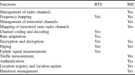
A group of BTSs are connected to a particular base station controller (BSC), which manages the radio resources for them. The management functions include: the allocation of radio channels to the MSs on call set up, determining when the handover is required, identifying suitable BTS, and controlling the transmitted power of an MS to ensure that it is sufficient to reach the serving BTS. The mobile stations normally send a measurement report about their received signal strength and quality every 480 ms to the BSC. With this information the BSC takes decision about- when to initiate the handovers to other cells, when to change the BTS transmitter power, and so on. The BSS is the connection between the mobile and the mobile service switching center (MSC). The BSC also translates the 13 kbps voice channel used over the radio link to the standard 64 kbps channel used by the public switched telephone network or ISDN. Typically, a BSC may control up to 40 BTSs and the capability of the BSCs varies from manufacturer to manufacturer. The functions of BTS and BSC are specified in Table 6.2.
Table 6.2 BTS and BSC Functions
6.3.3 Network Subsystem (NSS)
6.3.3.1 Mobile Services Switching Center (MSC)
The central component of the network subsystem is the mobile services switching center (MSC). It acts like a normal switching node of the PSTN or ISDN, and in addition it provides all the functionality needed to handle a mobile subscriber, such as registration, authentication, ciphering, location updating, handovers, generation of call records, and call routing to a roaming subscriber. These services are provided in conjunction with several functional entities, which together form the network subsystem. The MSC provides the connection to the public fixed network (PSTN or ISDN). Signaling between functional entities uses the ITUT signaling system number 7 (SS7), which is used in ISDN and widely used in current public networks. The network operator may also select one or more MSCs to act as gateway MSCs (GMSC). This provides the interface between the PLMN and external networks. MSC does not contain information about particular mobile stations, so this information is stored in the location registers.
6.3.3.2 Home Location Register (HLR)
A Home Location Register (HLR) is a database that contains semi-permanent mobile subscriber information for a wireless operators' entire subscriber base. Responsibilities of the HLR include: management of service profiles, mapping of subscriber identities (MISDN, IMSI), supplementary service control and profile updates, execution of supplementary service logic, for example, incoming calls barred and passing subscription records to the VLR. Two types of information are stored in the HLR: the subscriber information and part of the mobile information to allow incoming calls to be routed to the MSC for the particular MS. HLR subscriber information includes the international mobile subscriber identity (IMSI), location information, service restrictions, and supplementary services information, service subscription information, and so on. The HLR contains all the administrative information of each subscriber registered in the corresponding GSM network, along with the current location of the mobile. The current location of the mobile is in the form of a mobile station roaming number (MSRN, please refer to Section 6.8.5). Request information from the HLR or update the information contained in the HLR is handled by SS7 transactions with the MSCs and VLRs. The HLR also initiates transactions with VLRs to complete incoming calls and to update subscriber data. Traditional wireless network design is based on the utilization of a single Home Location Register (HLR) for each GSM network, but growth considerations are prompting operators to consider multiple HLR topologies and this can also be implemented as a distributed database.
6.3.3.3 Visitor Location Register (VLR)
A Visitor Location Register (VLR) is a database that contains temporary information concerning the mobile subscribers that are currently located in a given MSC serving area, but whose HLR is elsewhere. The information in VLR includes MSRN, TMSI, MS ISDN number, IMSI, HLD address, local MS identity (if any), the location area in which the MS has been registered, data related to supplementary services, and so on. When a mobile subscriber roams away from his home location into a remote location, SS7 messages are used to obtain information about the subscriber from the HLR, and to create a temporary record for the subscriber in the VLR. There is usually one VLR per MSC. The HLR and VLR, together with the MSC, provide the call routing and (possibly international) roaming capabilities of GSM.
6.3.3.4 Equipment Identity Register (EIR)
Each mobile station is identified by its International Mobile Equipment Identity (IMEI) number. Equipment Identity Register (EIR) is a database that contains a list of all valid IMEI numbers. This is used for security purposes and to prevent any illegal usage (see Section 8.1).
6.3.3.5 Authentication Center (AuC)
The authentication center (AuC) is an intelligent database concerned with the regulation of access to the network, ensuring that services can only be used by those who are entitled to do so and that the access is achieved in a secure way. The AuC authenticates each user (SIM card) that attempts to connect to the GSM core network (typically when the phone is powered on). It is a protected database that stores a copy of the secret key stored in each subscriber's SIM card, which is used for authentication and ciphering of the radio channel. Generally, it contains the subscriber's secret key (Ki) and the A3 and A8 security algorithms. This is discussed in detail in Chapter 9.
6.3.4 Operation and Maintenance Subsystem (OMSS)
The Operations and Maintenance Center (OMC) provides the means by which operators control the networks. The Network Management Center (NMS) is concerned with the management of the entire network and generally has a wider operational role than an OMC. The OMC is a management system that oversees the GSM functional blocks. The OMC assists the network operator in maintaining satisfactory operation of the GSM network. It can be in charge of an entire public land mobile network (PLMN) or just some parts of the PLMN.
6.4 PLMN and Network Operators
The GSM system is divided into a number of separate operational networks, each being operated independently to a large extent from the others. Each of these networks is called a PLMN (Public Land Mobile Network). The licenses for operating a GSM network in a country have been granted by Government agencies or some other authority. The operator may be a private company (such as Orange, Airtel, Vodaphone, AT&T), a public company or an administration, who buy the frequency licenses to deploy the GSM network. So the PLMNs are operated by different operators and again each PLMN is interconnected with other PLMNs, PSTNs or data networks and provide global communication access to a mobile user. The access to PLMN services is achieved by means of air interface (discussed in the Chapter 7) involving radio communications between MS and land based base stations (BTS). Most countries have several PLMNs, whose coverage areas can overlap partially or completely through appropriate frequency planning. This may cause problems in the border areas of a country. So, one restriction that has been imposed by CEPT, is that the commercial coverage area of each PLMN should be confined within the borders of one country.
6.4.1 Hierarchy of GSM Network Entities
Typically based on a geographical area, different cellular system providers deploy their own GSM networks. Again in the same area, several GSM networks (belonging to different operators) can co-exist, as shown in the Figure 6.3, where over the same geographical area, operator A and operator B deploy their services. They have taken licenses for different radio frequencies (in a GSM band) to operate in the same zone. The MS belonging to operator A will have SIM-A whereas MS belonging to operator B will have SIM-B inside it.

Figure 6.3 GSM network deployment by different operators
Cell sizes vary from 100 m up to 35 km depending on user density, geography, transceiver power, and so on. A cell site of any operator may typically contain a single BTS with one antenna subsystem (Omni-directional antenna, transmitting power equally in all directions) or a cell is split into several sectors (this is called sectorization) and involves dividing the cell into number of sectors (see Figure 6.4). One way to think about sectors is to consider them as separate smaller cells covering particular zones using directional antennas. Thus the advantage here is that the base stations corresponding to these divided sectors are co-located, which leads to saving of space, resources, and cabling. Sectorization is achieved by having a directional antenna at the base station that focuses the transmissions into the sector of interest and is designed to be null in other sectors. The ideal end result is an effective creation of new smaller cells without the added burden of new base stations and network infrastructure. This can help to increase network capacity and also to reduce the required transmission power.
The hierarchy of GSM network entities is shown in the Figure 6.5.
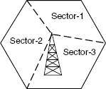
Figure 6.4 Sectorization of a cell

Figure 6.5 Hierarchy of GSM network entities
6.4.2 GSM Network Areas
The GSM network is made up of geographic areas. As shown in Figure 6.6, these areas include cells, location areas (LAs), MSC/VLR service areas, and public land mobile network (PLMN) areas. The cell is the area, where radio coverage is given by one base transceiver station (BTS). The GSM network identifies each cell via the cell global identity (CGI) number assigned to each cell. The location area is a group of cells. It is the area in which the subscriber will be paged. Each LA is served by one or more base station controllers, but only by a single MSC. Each LA is assigned a location area identity (LAI) number. An MSC/VLR the service area represents the part of the GSM network that is covered by one MSC and which is reachable, as it is registered in the VLR of the MSC. The PLMN service area is an area served by one network operator.

Figure 6.6 GSM network areas
As described earlier, there can be several network operators for a GSM service area. Hence there can be several PLMNs belonging to different operators in a GSM service area.
6.4.3 Objectives of a GSM PLMN
A GSM PLMN cannot establish calls autonomously other than local calls between mobile subscribers. In most cases, the GSM PLMN depends upon the existing wire-line networks to route the calls via PSTN. Most of the time the service provided to the subscriber is a combination of the access service by a GSM PLMN and the service by some existing wire-line network. The general objectives of a GSM PLMN are: (1) to provide the subscriber a wide range of services and facilities, both voice and data, that are compatible with those offered by existing networks (PSTN, ISDN, etc.); (2) to introduce a mobile service system that is compatible with the ISDN; (3) to provide facilities for automatic roaming, locating, and updating of mobile subscribers; and (4) efficient use of the frequency spectrum.
6.4.4 PLMN
As discussed previously, a GSM network is a public land mobile network (PLMN). GSM uses the following sub-division of the PLMN.
- Home PLMN (HPLMN) – The HPLMN is the GSM network to which a GSM user originally subscribed to. GSM user's subscription data reside in the HLR of HPLMN. During registration in another PLMN, the HLR may transfer the subscription data to a VLR or to a GMSC during mobile terminating call handling. The HPLMN may also contain various service nodes, such as a short message service center (SMSC), service control point (SCP), and so on.
- Visitor PLMN (VPLMN) – The VPLMN is the GSM network where a subscriber is currently registered. Originally the subscriber may be registered in HPLMN (or in another PLMN).
- Interrogating PLMN (IPLMN) – The IPLMN is the PLMN containing the GMSC that handles mobile terminating (MT) calls. GMSC always handles the MT calls in the PLMN, regardless of the origin of the call. For most operators, MT call handling is done by a GMSC in the HPLMN; in this case, the HPLMN is the same as IPLMN. Once the call has arrived in the HPLMN, the HPLMN acts as IPLMN. When basic optimal routing (BOR) is applied, the IPLMN is not the same PLMN as the HPLMN.
6.5 GSM Mobility and Roaming
Roaming in the GSM network is possible through the separation of switching capability and subscription data. It should be noted that the grouping of several operationally independent PLMNs and forwarding data among them, enables the roaming service, in which the user can move across areas but keeping access to their subscribed services linked to their SIM. This means that the PLMNs should communicate between themselves to offer the user mobility. A GSM subscriber's subscription data is permanently registered in the HLR of HPLMN. The GSM operator is responsible for provisioning this data in the HLR. However, whatever the subscription conditions may be, an emergency call is the only service that is available anywhere in the system. The MSC and GMSC in a PLMN are not specific for one subscriber group. The switching capability of the MSC in a PLMN may be used by that PLMN's own subscribers, and also by inbound roaming subscribers. For example, one GSM user, who is a subscriber of PLMN-1, roams to PLMN-2. The HLR in PLMN-1 transfers the user's subscription data to the MSC/VLR in PLMN-2. The subscriber's subscription data remain in that MSC/VLR as long as the user is served by a BSS that is connected to that MSC. Even when the user switches the MS OFF and later ON again, the subscription data remain in the MSC. When MS is being switched off for an extended period of time, then the subscription data will be purged from the MSC. When the subscriber switches MS on again, the subscriber has to re-register with the MSC, which entails the MSC asking the HLR in the HPLMN to re-send the subscription data for that subscriber.
When a subscriber moves from one MSC service area (such as MSC-1) to another MSC service area (such as MSC-2), the HLR will instruct MSC-1 to purge the subscription data of this subscriber and will send the subscription data to MSC-2.
6.6 GSM PLMN Services
The GSM PLMN defines a group of communication capabilities that the service providers can offer to its subscribers. Features that can be supported in the GSM network, such as establishing a voice call, establishing a data call, sending a short message, and so on, are classified as basic services. The user needs to have a subscription in order to use the GSM basic service. The handling of basic services is fully standardized. Thus, when the subscriber roams into another GSM network, the user may use the basic services (which he/she subscribed to) in that network (provided that that those basic services are also supported in that new network). The HLR will send a list of subscribed basic services to the MSC/VLR during registration. When a GSM subscriber initiates a call, the MS supplies a set of parameters describing the circuit switched connection that is requested to the serving MSC. The MSC uses these to derive the basic service for this call. The rules for deriving the basic service are specified in GSM TS 09.07. The MSC then checks whether the subscriber has a subscription to the requested basic service, that is, whether the subscription data in the VLR contains that basic service. If the service is not subscribed to, then the MSC does not allow the call. The basic service is not transported over ISUP.
- Basic services are divided into two groups: tele-services and bearer services.
- Bearer Services – These services give the subscriber the capacity required to transmit appropriate signals between certain access points (mobile user and network interfaces.), such as asynchronous data and synchronous data bearer services.
- Tele-services – The tele-services are telecommunication services as well as functions that enable communication between users, and are based on protocols agreed on by the network operators. Examples include speech transmission, SMS, e-mail, facsimile, teletext transmission. Please refer to GSM TS 02.03 for the available tele-services (TS).
- Supplementary Services are the services offered to enrich the user experiences, and are modified or supplement the basic telecommunication services. They are offered together or in association with basic communication services. For example, the ability to put calls on hold, call waiting, and caller-ID, and so on. Supplementary services may be provisioned for an individual basic service or for a group of basic services, for example, a subscriber may have the barring of all outgoing calls for all tele-services and all bearer services, except SMS (tele-service group 20). Such a subscriber is barred from establishing outgoing calls (except for emergency calls), but may still send short messages. Some supplementary services may be activated or deactivated by the user. Examples include call forwarding and call barring. An operator may decide to bar certain subscribers or subscriber groups from modifying their supplementary services.
In addition, we have the value added services. Value added services are supplied by the respective service provider or network operator, and can be transmitted either via a normal telephone call or via SMS: examples include reserving a hotel room, a flight or a hire car.
6.7 GSM Interfaces
6.7.1 Radio Interface (MS to BTS)
The air interface between the BTS and MS is known as the Um interface. The manufacturers of network and MS might not be same, but these have to be compliant with each other, in order to work together in a GSM system. The air interface is defined, so that MS and network manufacturers can design their equipment independently following the standards so that the outcomes will be compatible. More about this and the radio transmitter design aspect will be discussed in the next chapter.
6.7.2 Abis Interface (BTS to BSC)
The interface between BTS and BSC is known as Abis standard interface. The primary functions carried over this interface are traffic channel transmissions, radio channel management, and terrestrial channel management. This interface mainly supports two types of communication links: (1) traffic channels at 64 kbps, which carry speech or user data for a full or half rate radio traffic channel, and (2) signaling channels at 16 kbps, which carry information for BSC-BTS and BSC-MSC signaling. The BSC handles LAPD channel signaling for every BTS carrier. The lower three layers are based on the OSI/ITU-T recommendation: physical layer (ITU-T recommendation G.703 and GSM recommendation-08.54), data link layer [GSM recommendation 08.56 (LAPD)], and network layer (GSM recommendation 08.58). Transparent and non-transparent are the two types of messages handled by the traffic management procedure part of the signaling interface. BTS does not analyze the transparent messages between the MS and BSC-MSC.
6.7.3 A Interface (BSC to MSC)
The “A” interface is used for interconnections between the BSS radio subsystem and MSC. The physical layer of the “A” interface supports a 2 Mbps standard CCITT digital connection. The signaling transport uses the message transfer part and the signaling connection control part of SS7. The data transfer and protocol on these interfaces are discussed in detail in the Chapter 8.
6.8 GSM Subscriber and Equipment Identity
The GSM system distinguishes explicitly the user and the devices and deals with these accordingly. The user and mobile equipment in the system separately get their own internally unique identifiers. The user identity is associated with a subscriber identity module (for example, IMSI associated with SIM) and the device identity is associated with the equipment number (for example, IMEI associated with mobile equipment). These are described in the next section. An MS has a number of identities including the International Mobile Equipment Identity (IMEI), International Mobile Subscriber Identity (IMSI), and the ISDN number. These are needed for management of subscriber mobility and for addressing all the network elements.
6.8.1 International Mobile Equipment Identity (IMEI)
The IMEI (International Mobile Equipment Identity) is a unique 15-digit code used to identify an individual GSM mobile station in a GSM network. It is stored inside the mobile device by programming the EPROM inside the MS and should not be changed subsequently. When new mobile equipment is registered for the first time for use in a network, its IMEI number is stored in the Equipment Identity Register (EIR) of the network.
IMEI = TAC + FAC + SNR + spare
where the TAC (type approval code) is determined by a central GSM/PCS body (6 digits), the FAC (final assembly code) identifies the manufacturer (2 digits), the SNR (serial number) uniquely identifies all equipment within each TAC and FAC (6 digits), and a spare (1 digit).
The format of an IMEI is AABBBB–CC-DDDDDD-E. The significance of each digit is explained in the Table 6.3.
| Digit | Significance |
| AA | Country code |
| BBBB | Final assembly code |
| CC | Manufacturer code. This varies according to the manufacturer, such as for NOKIA it is 10 or 20 and MOTOROLA it is 07 |
| DDDDDD | Serial number |
| E | Unused |
An IMEI is marked as invalid if it has been reported stolen or is not type approved. IMEI numbers are classified as follows. (1) White – valid GSM mobile stations. The WHITE list contains the series of IMSIs that have been allocated to MEs and can be used legally on the GSM network. (2) Grey – GSM mobile stations to be tracked. The network operator use a GREY list to hold the IMSIs of MEs that must be tracked by the network for evaluation purpose. (3) Black – barred mobile stations. The BLACK list contains the IMSIs of all MEs that must be barred from accessing the GSM network. This will contain the IMSIs of stolen and malfunctioning MEs.
The EIR is used to store three different lists of IMSIs. The network commands the MS to send its IMEI number during a call, or access attempt. Once it receives the IMEI number, the IMEI is passed to the EIR by the serving MSC and the IMEI check is performed in the EIR (black or white listed) and the result of the IMEI check is returned by the EIR to the serving MSC. EIR checks whether this is in a black or white list and if it is found that it is included in the black list, then the network simply send an “illegal ME” message and terminate the call or access attempt.
The IMEI number of most mobile phones can be displayed by dialing the code *# 06 #. Usually this is printed on the compliance plate under the battery.
6.8.2 International Mobile Subscriber Identity (IMSI)
The IMSI is a unique non-dialable number allocated to each mobile subscriber in the GSM system that identifies the subscriber and user subscription within the GSM network. IMSI is assigned to an MS at the time of subscription time by the network provider, when the subscriber receives a new SIM card. This is stored inside the subscriber identity module (SIM) and in the network side it is also stored in the HLR. The IMSI is a unique 15-digit code used to identify an individual user on a GSM network. It consists of three components: (1) mobile country code (MCC) – a 3 digits (home country), (2) mobile network code (MNC) – 2 digits (home GSM PLMN), and (3) mobile subscriber identity number (MSIN) – 10 digits.
6.8.3 Temporary International Mobile Subscriber Identity (TIMSI)
The TIMSI is a pseudo-random number generated from the IMSI number. The TIMSI is introduced in order to avoid the need to transmit the IMSI over-the-air, which helps to keep the IMSI more secure. The TMSI is assigned to an MS by VLR after the initial registration. This only has local significance in the area handled by the VLR. It is not passed to HLR. The maximum number of bits that can be used for the TMSI is 32. The TMSI is also stored temporarily in the SIM. Before the mobile is switched off, the current TMSI is stored into the SIM, so that during the next registration process this same number can be used to make the initial process faster.
6.8.4 Mobile Subscriber ISDN Number (MSISDN)
MSISDN is the mobile station's real telephone number, through which it is called by another party. Primarily the MSISDN and IMSI are separated, because of the confidentiality of the IMSI, as the IMSI should not be made public. One cannot derive the subscriber identity from the MSISDN, unless the association of IMSI and MSISDN as stored in the HLR has been made public. So using of a false identity is difficult. In addition to this, a subscriber can hold several MSISDN numbers for the selection of different services depending on the SIM. Each MSISDN of a subscriber is reserved for a specific service (voice, data, fax, etc.). The MSISDN categories follow the international ISDN numbering plan and therefore have the following structure: (1) country code (CC) – up to 3 digits in place; (2) national destination code (NDC) – typically 2–3 decimal places; and (3) subscriber number (SN) – maximum 10 decimal places. The MSISDN has a maximum length of 15 decimal digits. It is also stored in the HLR of the network. The country is internally standardized, complying with ITU-T E.164 series. For example, India has the country code 091, the USA 001, and so on. The national operator or regulatory administration assigns the NDC as well as the subscriber number SN.
6.8.5 Mobile Station Roaming Number (MSRN)
The mobile station roaming number (MSRN) is a temporary location dependent ISDN number. It is assigned by the locally responsible VLR to each mobile station in its area. Calls are routed to the MS by using the MSRN. On request the MSRN is passed to the HLR then to the GMSC. The MSRN has the same structure as the MSISDN: MSRN = CC + NDC + SN. The components of CC and NDC are determined by the visited network and depend on the current location. The SN is assigned by the current VLR and is unique within the mobile network. The assignment of MSRN is done in such a way that the currently responsible switching node MSC in the visited network (CC + NDC) can be determined from the subscriber number. The MSRN can be assigned in two ways by the VLR: either at the registration when the MS enters into a new location area (LA) or each time when the HLR requests it for setting up a connection for incoming calls to the MS. In the first case, MSRN is also passed on from the VLR to HLR, where it is stored for routing. In the case of the incoming call, the MSRN is first requested from the HLR of the mobile station. This way currently responsible MSC can be determined, and the call can be routed to this switching node. Additional localization information can be obtained from responsible VLR. In the second case, the MSRN can not be stored in the HLR, as it is only assigned at the time of call set-up. Therefore the address of the current VLR must be stored in the table of the HLR. Once the routing information is requested from the HLR, the HLR itself goes to the current VLR and uses unique subscriber identification (IMSI and MSISDN) to request a valid roaming number MSRN. This allows further routing of a call.
6.8.6 Location Area Identity (LAI)
Each LA of a PLMN has its own identifier. The location area identifier (LAI) is also structured hierarchically and internationally unique, with LAI again consisting of an internationally standardized part and an operator dependent part: (1) country code (CC) – 3 decimal digits; (2) mobile network code (MNC) – 2 decimal places; and (3) location area code – maximum 5 decimal places. The LAI is broadcasted regularly by the BTs on the BCCH channel. Thus each cell is identified uniquely on the radio channel as belonging to an LA, and each MS can determine its current location through the LAI. If the LAI that is heard by the MS changes, the MS notices this LA change and requests the updating of it location information in the VLR and HLR – this is known as location update. The mobile station itself is responsible for monitoring the local conditions for signal reception, to select the base station that can be received best and to register with the VLR of that LA which the current base station belongs to. The LAI is requested from the VLR, if the connection for an incoming call has been routed to the current MSC using MSRN. This determines the precise location of the mobile station where the mobile can be subsequently paged. When the mobile station answers the exact cell and the base station becomes known, this information then can be used for call switching.
6.8.7 Local Mobile Subscriber Identity (LMSI)
The VLR can assign an additional searching key to each mobile station within its area to accelerate the database access. This is the local mobile station identity. Generally, an LMSI contains of 4 octets. The LMSI is assigned when mobile station registers with the VLR and is also sent to the HLR. The LMSI is not used any further by the HLR, but each time messages are sent to the VLR concerning a mobile station, the LMSI is added, so the VLR can use the short searching key for transactions concerning this MS. This type of additional identification is only used when the MSRN is newly assigned with each call. In this case, fast processing is very important to achieve short times for call set-up. As for the TMSI, an LMSI is also assigned in an operator specific way, and it is only unique within the administrative area of a VLR.
6.8.8 Cell Identifier (CI)
Within an LA, the individual cells are uniquely identified with a cell identifier (CI), which contains a maximum of 2 × 8 bits. Together with the global cell identity (LAI + CI), cells are thus also internationally defined in a unique way. In GSM, during execution of handover or after the handover is done, BSS informs the core network (CN) about the new cell that is being used by the MS.
6.8.9 Base Station Identity Code (BSIC)
In order to distinguish neighboring base stations in the GSM network, the BTSs are assigned a unique base transceiver station identity code (BSIC) which consists of two parts: (1) network color code (NCC) – color code within a PLMN (3 bits); and (2) base station color code (BCC) – BTS color code (3 bits). The BSIC is broadcasted periodically by the base station via the synchronization channel (SCH).
6.8.10 Identification of MSCs and Location Registers
MSCs and location registers (HLR and VLR) are addressed with ISDN numbers. In addition, they may have signaling point code (SPC) within a PLMN, which can be used to address them uniquely within the signaling number 7 network.
6.8.11 PIN and PUK
PIN stands for personal identification number. A PIN code is a numeric value used in certain systems as a password to gain access, and for authentication. A PIN is a 4–8 digit access code which can be used to secure your mobile telephone from use by others. PIN2 (personal identity number 2) is a 4–8 digit access code which can be used to access the priority number memory and the cost of calls. The PUK (personal unblocking key) and PUK2 are used to unlock the PIN and PIN 2 codes, respectively, if your SIM card is blocked. Generally, to change SIM card PIN the user has to dial ** 04 * old PIN * new PIN * new PIN #.
Further Reading
3GPP specification GSM TS 02.03. Teleservices Supported by a GSM Public Land Mobile Network (PLMN).
Mehrotra, A. (1997) GSM System Engineering, Artech House, Boston.
Mouley, M. and Pautet, M.-B. (1992) The GSM System for Mobile Communications, F-99120, Telecom Publisher, Palaiseau, France.
Steele, R. Lee, C.-C., and Gould, P. (2001) GSM, cdmaOne and 3G Systems, John Wiley & Sons Ltd., Chichester
Yacoub, M.D. (2002) GSM Overview, Wireless Technology, CRC Press, Boca Raton, ISBN 0-8493-0969-7.