
13
UMTS Radio Modem Design: From Speech to Radio Wave
13.1 Introduction
We have already discussed CDMA techniques in detail in Chapter 5. Before reading this chapter, readers should consult Chapter 5 for a better understanding. The present chapter discusses the WCDMA air interface (also referred as UMTS terrestrial radio access (UTRA), which has been developed by the third-generation partnership project – 3GPP, and the associated radio modem design aspects. 3GPP has the goal of harmonizing and standardizing, in detail, the similar types of proposals that have been prepared by ETSI, ARIB, TTC, TTA, and T1.
Direct-sequence code division multiple access (DS-CDMA) is used as the air medium multiple access technique. We have seen earlier that spread spectrum techniques can be used to achieve a greater data rate, but the chip rate needs to be increased, which in turn demands for more bandwidth. This is why in WCDMA the bandwidth is widened further to accommodate more users or to support an increased data rate. WCDMA has two modes characterized by the duplex method: FDD (frequency division duplex) and TDD (time division duplex), for operating with paired and unpaired bands, respectively. In the FDD version of UMTS, a physical channel is defined by its code and carrier frequency, while in TDD it is in terms of its code, carrier frequency, and time slot.
- FDD: In this duplex method the uplink and downlink transmission use two separate radio frequency bands. A pair of frequency bands, which are separated by a specified frequency range, will be assigned for this system.
- TDD: Here uplink and downlink transmissions are carried over the same radio frequency by using synchronized time intervals. In TDD, time slots in a physical channel are divided into transmission and reception parts. Information on uplink and downlink are transmitted reciprocally. UTRA TDD has two options, with chip rates of 3.84 and 1.28 Mcps. In UTRA TDD, there is a TDMA component in the multiple access in addition to DS-CDMA. Thus the multiple access has also often been denoted as TDMA/CDMA due to the added TDMA nature. A physical channel is therefore defined as a code (or number of codes) and additionally in the TDD mode the sequence of time slots completes the definition of a physical channel.
13.1.1 FDD System Technical Parameters
Before going to the detailed discussion, the main technical parameters of WCDMA-FDD mode system are summarized here.
- Frequency band: (1920–1980 MHz) and (2110–2170 MHz) – Frequency division duplex for uplink and downlink, respectively
- Minimum frequency band required (bandwidth): ~5 MHz (for uplink and downlink)
- Frequency re-use factor: 1
- Carrier spacing: 4.4–5.2 MHz
- Maximum number of (voice) channels on 2 × 5 MHz: ~196 (spreading factor 256 UL, AMR 7.95 kbps)/~98 (spreading factor 128 UL, AMR 12.2 kbps)
- Voice coding: AMR codecs (4.75–12.2 kHz, GSM EFR = 12.2 kHz) and SID (1.8 kHz)
- Channel coding: Convolutional coding, Turbo code for high data rate
- Antenna multiplexing: Duplexer needed (190 MHz separation), asymmetric connection supported
- Tx/Rx isolation: MS – 55 dB, BS – 80 dB
- Receiver type: Rake
- Receiver sensitivity: Node B − 121 dBm, mobile − 117 dBm at BER of 10−3
- Data type: Packet and circuit switch
- Modulation: QPSK (downlink) and BPSK (uplink)
- Pulse shaping: Root raised cosine, roll-off = 0.22
- Chip rate: 3.84 Mcps
- Channel raster: 200 kHz
- Maximum user data rate (physical channel): ~2.3 Mbps [spreading factor 4, parallel codes (3 DL/6 UL), ½ rate coding], but interference limited
- Maximum user data rate (offered): 384 kbps (in mobile environment – outdoor), higher rates (~2 Mbps) in the near future. HSPDA will offer data speeds up to 8–10 Mbps (and 20 Mbps for MIMO systems)
- Channel bit rate: 5.76 Mbps
- Frame length: 10 ms
- Number of slots/frame: 15
- Number of chips/slot: 2560 chips
- Handovers: Soft, softer, (inter-frequency: hard)
- Power control period: Time slot = 1500 Hz rate
- Power control step size: 0.5, 1, 1.5 and 2 dB (variable)
- Power control range: UL 80 dB, DL 30 dB
- Mobile peak power: Power class 1, +33 dBm (+1 dB/−3 dB) = 2W; class 2, + 27 dBm; class 3, + 24 dBm; class 4 + 21 dBm
- Number of unique base station identification codes: 512/frequency
- Physical layer spreading factors: 4 … 256 UL, 4 … 512 DL.
13.2 Frequency Bands
UTRA/FDD is designed to operate in the following paired frequency bands (Figure 13.1) and with the following Tx–Rx frequency separation, as described in Table 13.1.
The chip rate of the system is 3.84 Mcps, for example, 3 840 000 chips will always be transmitted over the air per second. As we know, the data will be multiplied with the chip signal. Now, based on the transmission data rate needed (which varies from channel to channel), the number of data bits per second will be different. The ratio of the number of chips to the number of data bits is defined as spreading factor (SF). The spreading factor ranges from 256 to 4 in the uplink and from 512 to 4 in the downlink. Thus, the respective modulation symbol rates vary from 960 to 15 ksymb/s (7.5 ksymb/s) for FDD uplink.
Table 13.1 UTRA FDD frequency bands
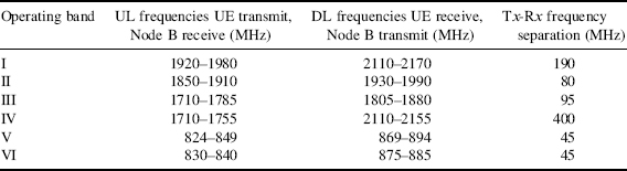

Figure 13.1 Frequency bands allocation
13.3 Radio Link Frame Structure
The data carried by the UMTS/WCDMA transmissions is organized into frames, slots and channels. In this way all the payload data, and the control data, can be carried in an efficient manner. UMTS uses CDMA techniques (WCDMA) as its multiple access technology, but it additionally uses time division techniques with a slot and frame structure to provide the full channel structure.
Physical channels are defined by a specific carrier frequency, scrambling code, channelization code (optional), time start and stop (giving a duration), and on the uplink, relative phase (0 or π/2). Time durations are defined by start and stop instants, measured in integer multiples of chips. Based on this, it is divided into three sub-categories.
- Radio Frame: A radio frame is a processing duration of 10 ms. The chip rate used here is 3 840 000 chips per second, so the total number of chips in a 10 ms duration (for example, in one radio frame) will be 38 400 chips. This radio frame is again divided into smaller time intervals, which are known as slots. One radio frame consists of 15 slots (Figure 13.2).
Figure 13.2 Radio link frame structure
- Slot: A slot is a duration of 10 ms/15 = 0.667 ms. In one slot, the total number of chips will be = 38 400/15 = 2560 chips.
- Super Frame: This consists of 72 radio frames and has a duration = 72 × 10 ms = 720 ms.
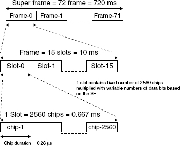
One symbol consists of a number of chips. The number of chips per symbol is equivalent to the spreading factor of the physical channel. The default time duration for a physical channel is continuous from the instant when it is started to the instant when it is stopped. Physical channels which are not continuous will be discussed in detail later.
Several channels are required in the forward and reverse link for communication between BS and UE. In Figure 13.3, the requirement for different types of channel is indicated.
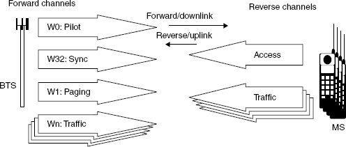
Figure 13.3 Different channel requirement for uplink and downlink
What do we need to separate or distinguish in the system?
- sectors/cells (BTSs)
- mobile terminals (UE)
- directions (for uplink and downlink directions)
- channels
Uplink and downlink are separated by two separate 5 MHz bands. Sectors/cells are separated by primary scrambling code. Mobile terminals are separated by scrambling code. Channels are separated by spreading/channelization code (and scrambling code).
13.4 Channel Structure
The channels are categorized into three different levels, according to the information carried by the channel: (1) logical level channels; (2) transport level channels; and (3) physical level channels. The logical channels are related to what is transported; transport channels are the way in which data are transported, and the physical channels deal with how data are transported and govern the physical characteristics of the signal. Figure 13.4 shows the scope of these channels over the entities in UMTS architecture.
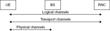
Figure 13.4 Visibility of different channels in the system
13.4.1 Logical Channels
A set of logical channel types are defined for different types of data transfer services as offered by MAC (see Table 13.2). Logical channels are broadly classified into two groups:
- Control Channels – for the transfer of control plane information.
- Traffic Channels – for the transfer of user plane information.
The air interface protocol architecture is shown in Figure 13.5, and this is discussed in more detail in the next chapter. Introduction of different channels and usage of channels are shown in this architecture.
13.4.2 Transport Channels
Transport channels are channels supplied from the physical layer to the MAC sublayer (L2) or vice versa. A transport channel is defined by how and with what characteristics data are transferred over the air interface. Generally, it is classified into two groups:
- Dedicated channels – using inherent addressing of UE.
- Common channels – using explicit addressing of UE if addressing is needed.


Figure 13.5 Air interface protocol architecture and introduction of different channel hierarchy
The main difference between them is that a common channel is a resource divided between all or a group of users in a cell, whereas a dedicated channel resource, identified by a certain code on a certain frequency, is reserved for a single user only.
13.4.2.1 Dedicated Transport Channels
Only one type of dedicated transport channel exists, the dedicated channel (DCH).
DCH – Dedicated Channel
The dedicated channel (DCH) is a downlink or uplink transport channel. The DCH is transmitted over the entire cell or over only a part of the cell using beam-forming antennas. It is assigned individually to each UE. The dedicated transport channel carries all the information intended for the given user coming from layers above the physical layer, including data for the actual service, as well as higher layer control information. The content of the information carried on the DCH is not visible to the physical layer, thus higher layer control information and user data are treated in the same way. Naturally the physical layer parameters set by UTRAN may vary between control and data. The dedicated transport channel is characterized by features such as fast power control, fast data rate change on a frame-by-frame basis. The dedicated channel supports soft handover.
13.4.2.2 Common Transport Channels
There are six types of common transport channels: BCH, FACH, PCH, RACH, CPCH, and DSCH.
BCH – Broadcast Channel
The broadcast channel (BCH) is a downlink transport channel that is used to broadcast system- and cell-specific information. It is transmitted at a fixed rate and always transmitted over the entire cell and has a single transport format. As the terminal cannot register to the cell without the possibility of decoding the broadcast channel, so this channel is transmitted with relatively high power in order to reach all the users within the intended coverage area.
FACH – Forward Access Channel
The forward access channel (FACH) is a downlink transport channel that carries control information to terminals known to be located in the given cell. The FACH is transmitted over the entire cell or over only a part of the cell using beam-forming antennas. This is used, for example, after a random access message has been received by the base station. It is also possible to transmit packet data on the FACH. There can be more than one FACH in a cell. With more than one FACH, the additional channels can have a higher data rate. This may be shared by multiple UEs. The FACH can be transmitted using slow power control.
PCH – Paging Channel
The paging channel (PCH) is a downlink transport channel used for transmitting paging information, that is, when the network wants to initiate communication with the mobile terminal. The identical paging message can be transmitted in a single cell or in several cells, depending on the system configuration. The terminals must be able to receive the paging information in the whole cell area. The PCH is always transmitted over the entire cell. The transmission of the PCH is associated with the transmission of physical-layer generated paging indicators, to support efficient sleep-mode procedures. The design of the paging channel also affects the terminal's power consumption in the standby mode. The less often the terminal has to tune to listen for a possible paging message, the longer the terminal's battery life.
RACH – Random Access Channel
The random access channel (RACH) is an uplink transport channel used for transmitting control information and user data, such as requests to set up a connection. It can also be used to send small amounts of packet data from the terminal to the network. The RACH is always received from the entire cell, applied in random access, and used for low-rate data transmissions from a higher layer. The RACH is characterized by a collision risk and by being transmitted using open loop power control.
CPCH – Common Packet Channel
The common packet channel (CPCH) is an uplink transport channel. CPCH is associated with a dedicated channel on the downlink which provides power control and CPCH control commands (for example, emergency stop) for the uplink CPCH. The uplink CPCH is an extension to the RACH channel that is intended to carry packet-based user data in the uplink direction. The reciprocal channel providing the data in the downlink direction is the FACH. In the physical layer, the main differences to the RACH are the use of fast power control, a physical layer-based collision detection mechanism, and a CPCH status monitoring procedure. The uplink CPCH transmission may last several frames in contrast with one or two frames for the RACH message. The CPCH is characterized by initial collision risk and by being transmitted using inner loop power control. It is applied in random access and used primarily for high rate bursty data transmissions.
DSCH – Downlink Shared Channel
The downlink shared channel (DSCH) is a downlink transport channel shared by several UEs. The DSCH is associated with one or several downlink DCH. The DSCH is transmitted over the entire cell or over only a part of the cell using beam-forming antennas.
The downlink shared channel (DSCH) is a transport channel intended to carry dedicated user data and/or control information; it can be shared by several users. In many respects it is similar to the forward access channel, although the shared channel supports the use of fast power control as well as variable bit rate on a frame-by-frame basis. The DSCH does not need to be heard in the whole cell area and can employ the different modes of transmit antenna diversity methods that are used with the associated downlink DCH. The downlink shared channel is always associated with a downlink DCH.
The mapping of logical to transport channels is shown in Figure 13.6.

Figure 13.6 Mapping between logical and transport channels
13.4.2.3 Frame Structure of Transport Channels
As discussed earlier, UTRA channels use a 10 ms radio frame structure. The frame structure also employs a longer period, called the system frame period. The system frame number (SFN) is a 12-bit number and is used by procedures that span more than a single frame. Physical layer procedures, such as the paging procedure or random access procedure, are examples of procedures that need a longer period than 10 ms for correct definition.
13.4.2.4 Transport Channels Mapping on to the Physical Channels
Each transport channel is accompanied by the transport format indicator (TFI) and appears at each time event at which data are expected to arrive for the specific transport channel from the higher layers. The physical layer combines the TFI information from different transport channels into the transport format combination indicator (TFCI). The TFCI is transmitted in the physical control channel to inform the receiver about the transport channels that are active for the current frame; the exception to this is the use of blind transport format detection (BTFD), which will be covered in connection with the downlink dedicated channels. The TFCI is decoded appropriately in the receiver and the resulting TFI is given to higher layers for each of the transport channels that can be active for the connection.
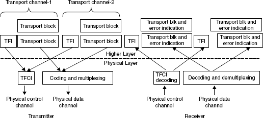
Figure 13.7 The interface between higher layers and the physical layer
As an example, Figure 13.7 shows two transport channels, which are mapped to a single physical channel, and error indication is also provided for each transport block. The transport channels may have a different number of blocks, and at any instant of time, all the transport channels will not necessarily have to be active. One physical control channel and one or more physical data channels form a single coded composite transport channel (CCTrCh). There can be more than one CCTrCh on a given connection but only one physical layer control channel is transmitted in such a situation.
Transport Formats/Configurations
The following parameters are used for transport formats or configurations.
- Transport block (TB): Basic unit of data exchanged between L1 and MAC for L1 processing.
- Transport block size: Number of bits in a TB.
- Transport block set (TBS): A set of TBs exchanged between L1 and MAC at the same time instant using the same transport channel.
- Transport block set size: Number of bits in a TBS.
- Transmission time interval (TTI): Periodicity at which a TBS is transferred by the physical layer on to the radio interface – {10, 20, 40, 80 ms}. MAC delivers one TBS to the physical layer every TTI.
- Transport format (TF): Format offered by L1 to MAC (and vice versa) for the delivery of a TBS during a TTI on a given transport channel (TrCH) – dynamic part (TB size, TBS size), semi-static part (TTI, type/rate of coding size of CRC). TB size, TBS size, TTI define the TrCH bit rate before L1 processing.
- Transport format set (TFS): A set of TFs associated with a TrCH. Semi-static part of all TFs in a TFS is the same.
- Transport format combination (TFC): Multiple TrCHs each having a TF. Authorized combination of the currently valid TFs that can be submitted to L1 on a CCTrCH, containing one TF from each TrCH.
- Transport format combination set (TFCS): This is a set of TFCs on a CCTrCH. Produced by RNC. TFCS is given to MAC by L3 for control. MAC chooses between the different TFCs specified in the TFCS. MAC has control over only the dynamic part of the TFs. Semi-static part relates to QoS (for example, quality) and is controlled by RNC admission control. Bit rate can be changed quickly by MAC with no need for L3 signaling.
- Transport format indicator (TFI): A label for a specific TF within a TFS. Used between MAC and L1.
- Transport format combination indicator (TFCI): Used to inform the receiving side of the currently valid TFC.
13.4.3 Physical Channels
Physical channels typically consist of a layered structure of radio frames and time slots, although this is not true for all physical channels. Depending on the channel bit rate of the physical channel, the configuration of the slots varies.
The Physical Resource – The basic physical resource is the code/frequency plane. In addition, on the uplink, different information streams may be transmitted on the “I” and “Q” branch. Consequently, a physical channel corresponds to a specific carrier frequency, code, and, on the uplink, the relative phase (0 or π/2) also.
The uplink and downlink physical channels are shown in Figure 13.8. For uplink and downlink different frequency bands are used (WCDMA-FDD), and inside uplink or downlink, for the various channels different spreading codes are used.
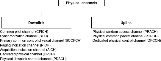
Figure 13.8 Uplink and downlink physical channels
13.4.3.1 Mapping of Transport Channels onto Physical Channels
Figure 13.9 summarizes the mapping of various transport channels onto different physical channels.
The DCHs are coded and multiplexed as will be described later, and the resulting data stream is mapped sequentially (first-in-first mapped) directly to the physical channel(s). The mapping of BCH and FACH/PCH is equally straightforward, where the data stream, after coding and interleaving, is mapped sequentially to the primary and secondary CCPCH, respectively. Also, for the RACH, the coded and interleaved bits are sequentially mapped to the physical channel, in this case the message part of the PRACH. Some channels (such as SCH, CPICH, etc.) are generated at the physical layer itself.
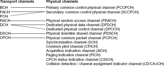
Figure 13.9 Transport-channel to physical-channel mapping
13.5 Spreading, Scrambling, and Modulation
As discussed in Chapter 5, in WCDMA, in addition to spreading, the scrambling operation is performed in the transmitter (Figure 13.10). This is required in order to separate the user terminals and base stations (cells/sectors) from each other. Scrambling is used on top of spreading, and it does not change the rate or signal bandwidth but only makes the signals from different sources separable from each other. With scrambling, it would not matter if the actual spreading were performed with identical codes for several transmitters.
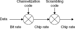
Figure 13.10 Relationship between spreading and scrambling operations
Transmissions from a single source are separated by channelization codes, that is, downlink connections within one sector and the dedicated physical channel in the uplink from one terminal are separated by this. The spreading/channelization codes of UTRA are based on the orthogonal variable spreading factor (OVSF) technique. The use of OVSF codes allows the spreading factor to be changed and orthogonality between different spreading codes of different lengths to be maintained. The codes are picked from the code tree, based on the data rate and channel number requirements (as we know, a lesser spreading factor, for example, more towards the left side of the tree, provides more actual data rate, and more towards the right-hand side of the tree provides more spreading factor value, such as more branches, which can be used for many simultaneous orthogonal channels), which is illustrated in Figure 13.11. Where the connection uses a variable spreading factor, the correct use of the code tree also allows despreading according to the smallest spreading factor. This requires that channelization code should only be used from the branch indicated by the code used for the smallest spreading factor.
There are certain restrictions as to which of the channelization codes can be used for a transmission from a single source. Another physical channel may use a certain code in the tree if no other physical channel to be transmitted using the same code tree is using a code that is on an underlying branch. The downlink orthogonal codes within each base station are managed by the radio network controller (RNC) in the network.
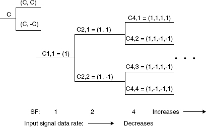
Figure 13.11 Channelization code tree
The functionality and characteristics of the scrambling and channelization codes are summarized in Table 13.3. The definition for the same code tree means that for transmission from a single source, from either a terminal or a base station, one code tree is used with one scrambling code on top of the tree. This means that different terminals and different base stations may operate their code trees totally independent of each other; there is no need to coordinate the code tree resource usage between different base stations or terminals.
13.5.1 Down Link (DL) Spreading and Modulation
The support of DL (Node B side) code generation and knowledge of the DL modulation scheme are mandatory at UE. The code generation and allocation scheme for the downlink direction is described below.
13.5.1.1 Channelization Codes
The DL channelization codes are derived from the channelization code tree. The code tree under a single scrambling code is shared by several users (all channels from the one sector are separated by different spreading codes and sectors are separated by sector specific unique primary scrambling code). As typically only one scrambling code is used per sector so only one code tree is used per sector in the base station. The common channels and dedicated channels share the same code tree resource. There is one exception for the physical channels: the synchronization channel (SCH) is not under a downlink scrambling code. In the downlink, the dedicated channel spreading factor does not vary on a frame-by-frame basis; the data rate variation is taken care of either by a rate matching operation or with discontinuous transmission, where the transmission is off during part of the slot. The channelization code for the P-CPICH is fixed to Cch,256,0 and the channelization code for the P-CCPCH is fixed to Cch,256,1.
Table 13.3 Functionality of channelization and scrambling code

Spreading and modulation for CPICH, S-CCPCH, P-SCCCH, PDSCH, PICH, and AICH channels are done in an identical way as for the DL DPCH. Spreading/modulation for P-CCPCH is done in exactly the same way as for the DL DPCH, except that the P-CCPCH is time multiplexed after spreading. P-SCH and S-SCH are code multiplexed and transmitted simultaneously during the first 256 chips of each slot. The SCH is non-orthogonal to the other DL physical channels.
13.5.1.2 Scrambling Code
The downlink scrambling uses long codes, the same Gold codes as in the uplink. The complex-valued scrambling code is formed from a single code by simply having a delay between the I- and Q-branches (Figure 13.12). The code period is truncated to 10 ms; no short codes are used in the downlink direction. A total of (218 − 1) number of scrambling codes, numbered from 0 to 262 142 can be generated, however not all are used. The downlink set of the (primary) scrambling codes is limited to 512 codes; otherwise the cell search procedure (described in Chapter 15, Section 15.5.1) would become excessive. The scrambling codes must be allocated to the sectors during the network planning, as is done for GSM for broadcast frequency planning in cells.

Figure 13.12 Complex scrambling
The downlink scrambling codes are divided into 512 sets. Each set consists of a primary scrambling code and 15 secondary scrambling codes. Overall, 8192 codes are allocated. In a compressed mode, each of these codes are associated with an even alternative scrambling code and an odd alternative scrambling code. The even alternative scrambling code corresponds to k + 8192; the odd alternative scrambling code corresponds to k + 16 384, where k corresponds to the code used from the 8192 scrambling code set. The set of primary scrambling codes is further divided into 64 scrambling code groups, each group consisting of 8 primary scrambling codes. The 64 groups have a one-to-one mapping to the sequence of secondary synchronization codes.
Each cell is allocated one, and only one, primary scrambling code and the PCCPCH + PCPICH is always transmitted using this primary scrambling code. The broadcast information is conveyed in the PCCPCH. The other downlink physical channels are transmitted with either the primary scrambling code or an associated secondary scrambling code. The x sequence is constructed using the polynomial 1 + X7 + X18, while the y sequence is constructed using the polynomial 1 + X5 + X7 + X10 + X18. The resulting sequences thus constitute segments of a set of Gold sequences. The scrambling codes are repeated for every 10 ms radio frame. A mixture of primary and secondary scrambling codes can be used in a transmission of CCTrCH. The code generator used to generate the downlink scrambling code is different to that of the code generator used to generate the uplink scrambling code. Refer to TS 25.213 Section 13.5.2.2 for details of the scrambling code generator.
The UE will contain a function for generating the downlink scrambling code. There will be multiple generators, one associated with each finger in the rake, to allow the UE to connect to multiple downlink transmissions derived from different cells. By virtue of the synchronization channels, the UE will derive the downlink scrambling code in use by the cell that it intends to camp onto. This code shall be reported to the higher layers. From this point, the system information decoded from the PCCPCH will then inform the UE of the primary scrambling codes for the neighboring/hierarchical cells. If more capacity is needed, then a secondary scrambling code needs to be introduced in the cell, and only those users not fitting under the primary scrambling code should use the secondary code. The biggest loss in orthogonality occurs when the users are shared evenly between two different scrambling codes.
13.5.1.3 Synchronization Codes
For synchronization purposes the network uses the synchronization channel (SCH), which uses synchronization codes (SC). SCH is introduced at the physical layer only and is not visible above the physical layer. SCH channels are treated in a different manner to the normal channels and as a result they are not spread using the OVSFs and PN scrambling codes. Instead they are spread using synchronization codes (SC). SCH are not under the cell specific primary scrambling code. The terminal (UE) must be able to synchronize to the cell before knowing the downlink scrambling code.
The synchronization channel for a cell is organized into a primary synchronization channel and secondary synchronization channel. The primary synchronization channel (or code) is a 256-chip sequence transmitted every slot, and every cell across the system (regardless of network operator) will transmit the same code. From the primary synchronization code, the UE will obtain slot and chip synchronization. The secondary synchronization channel is a sequence of 256-chip codes. A different code is transmitted on every slot, and this repeats over every 15 slots (or 10 ms), for example, periodic over a frame. There are 64 sets from which the secondary synchronization channels can be selected. These 64-sets correspond to the 64 primary scrambling code generators. (Sometimes the same code is used across two or more consecutive slots. Please refer to TS 25.213 for details of the code assignments.)
From the secondary synchronization channel the UE will obtain frame synchronization and be able to identify the primary scrambling code (here sectors are identified by primary scrambling, the same as for GSM, where BTSs are identified by broadcast frequency used by different BTS). Refer to TS 25.213 Section 5.2.3 for details of the synchronization codes used. The primary synchronization code is constructed as a so-called generalized hierarchical Golay sequence. The construction of secondary synchronization code words requires a Hadamard sequence, which can be obtained as the rows in a matrix H8 constructed recursively by:

There are altogether 16 secondary synchronization codes and 1 primary synchronization code (this primary synchronization code is common to all cells). The 16 secondary synchronization codes are arranged into 64 sequences (to identify the scrambling code group) such that the cyclic-shifts of these sequences are unique.
The modulating chip rate is 3.84 Mcps and in the downlink direction QPSK modulation is used.
13.5.2 Uplink Spreading and Modulation
13.5.2.1 Uplink Channelization Codes
OVSF channelization codes are used to preserve orthogonality between a user's different physical channels. The OVSF can be generated using the code tree in Figure 13.11. Alternatively, one may also use the following representation for generating OVSF codes.
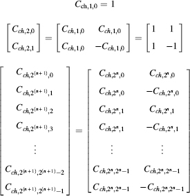
In the downlink direction, the OVSF is used to convey different users and different channels to a single user, whereas in the uplink direction, the OVSF is used to convey different channels from the user.
The UE will generate the channelization codes when given appropriate information by the higher protocol layers, and then it will use the same until that code is no longer required.
In the uplink direction the spreading factor on the DPDCH may vary on a frame-by-frame basis. The spreading codes are always taken from the earlier described code tree. When the channelization code is used for spreading, it is always taken from the same branch of the code tree, the despreading operation can take advantage of the code tree structure and avoid chip level buffering. The terminal provides data rate information, or more precisely the transport format combination indicator (TFCI), on the DPCCH, to allow data detection with a variable spreading factor on the DPDCH.
13.5.2.2 Uplink Scrambling Codes
There are 224 UL scrambling codes. All channels will use either long or short scrambling codes, except for PRACH, where only the long scrambling code is used. The UE will be able to generate long and short scrambling codes as dictated by the higher layers. Two separate scrambling code generators will be required to allow uplink communications with two cells (Figure 13.13). If communications is only with one cell, then the other scrambling code generator shall be switched off. The UE will initiate the uplink-scrambling generators with a 24-bit value that is provided by the higher layers. Note that two sets of scrambling code generator need to be initiated.

Figure 13.13 I/Q multiplexing with complex spreading
Long Scrambling Code
The long scrambling code has a period of 38 400 chips and repeats once in a 10 ms frame. The x sequence is constructed using the polynomial X25 + X3 + 1, while the y sequence is constructed using the polynomial X25 + X3 + X2 + X + 1. The resulting sequences thus constitute segments of a set of Gold sequences.
Short Scrambling Code
The short scrambling code has a period of 256 chips and repeats 150 times in a 10 ms frame. The long and short scrambling codes are generated as described by TS 25.213, Section 4.3.2. The UL short codes Sν(n), n = 0,1, …, 255, of length 256 chips are obtained by one chip periodic extension of S(2) sequences of length 255. This means that the first chip [Sν(0)] and the last chip [Sν(255)] of any UL short scrambling code are the same. The modulating chip rate is 3.84 Mcps. The uplink modulation of both DPCCH and DPDCH is BPSK. The complex scrambling codes are formed in such a way that the rotations between consecutive chips within one symbol period are limited to ±90°. The full 180° rotation can happen only between consecutive symbols.
13.6 Uplink Physical Channels
13.6.1 Dedicated Uplink Physical Channels
There are two types of uplink dedicated physical channels defined; (1) the uplink dedicated physical data channel (uplink DPDCH) and (2) the uplink dedicated physical control channel (uplink DPCCH). In the uplink, DPDCH and DPCCH are transmitted in parallel. The DPDCH and the DPCCH are I/Q code multiplexed within each radio frame. The uplink DPDCH is used to carry the DCH transport channel. At any point of time, there may be zero, one, or several uplink DPDCHs and only one uplink DPCCH on each radio link.
The uplink DPCCH is used to carry control information generated at layer-1. Layer-1 control information consists of known pilot bits to support channel estimation for coherent detection, transmit power-control (TPC) commands, feedback information (FBI), and an optional transport-format combination indicator (TFCI). The transport-format combination indicator informs the receiver about the instantaneous transport format combination of the transport channels mapped to the simultaneously transmitted uplink DPDCH radio frame. Figure 13.14 shows the frame structure of the uplink dedicated physical channels. Each radio frame of length 10 ms is split into 15 slots, each of length Tslot = 2560 chips, corresponding to one power-control period.

Figure 13.14 Frame structure for uplink DPDCH/DPCCH
In the uplink direction BPSK modulation is used, where each symbol is one bit. The parameter k in Figure 13.14 determines the number of bits per uplink DPDCH slot. It is related to the spreading factor SF of the DPDCH as SF = 2560/(2k*10). As k ranges from 0 to 6, so the DPDCH spreading factor may range from 256 down to 4. The spreading factor of the uplink DPCCH is always equal to 2560/10 = 256, that is, there are 10 bits per uplink DPCCH slot. The exact number of bits of the uplink DPDCH and the different uplink DPCCH fields (Npilot, NTFCI, NFBI, and NTPC) is given in the standard. Which slot format to use is configured by the higher layers. The FBI bits are used to support techniques requiring feedback from the UE to the UTRAN access point, including closed loop mode transmit diversity and site selection diversity transmission (SSDT).
13.6.1.1 Transmission of Uplink Dedicated Physical Control Channel (DPCCH) and Dedicated Physical Data Channel (DPDCH)
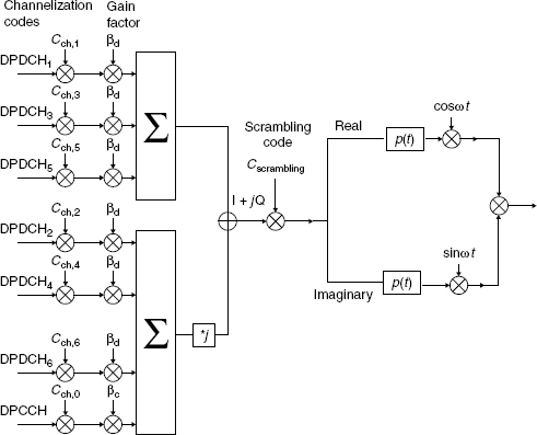
In uplink, DPDCP and DPCCH are transmitted in parallel. In the uplink direction the DPCCH and DPDCH output from the channel codec are processed in L1 as below, and which is shown in Figure 13.15.
- Mapping – A binary “0” is mapped to a real valued +1 and a binary “1” is mapped to a real valued −1.
- Channelization/Spreading – As different mobiles use different uplink scrambling codes, the uplink channelization codes may be allocated without coordination between different connections. The uplink channelization codes are always allocated in a predetermined manner. The DPCCH is always spread to chip rate (3.84 Mcps) by the channelization code Cch,256,0 (SF = 256), whereas the nth DPDCHn (0< = n< = 6) is spread to the chip rate by the channelization code Cch, SF,n.
- Combination – One DPCCH and up to six parallel DPDCHs can be transmitted simultaneously. The DPCCH spreading factor (SF) is always 256, while the DPDCH SF can vary from 4 to 256. After the channelization the real valued spread signals are weighted by gain factor βc (for DPCCH) and βd (for DPDCH), then the stream of real valued chips on the I and Q branches are summed and treated as a complex valued stream of chips. This is then scrambled by complex valued scrambling code Cscramb.
- Scrambling – The uplink scrambling code is decided by the network only. The mobile is informed in the downlink access grant message about what scrambling code to use. The scrambling code may, in rare cases, be changed during the duration of the connection. The change of uplink scrambling code is negotiated over the DCCH. There are 224 uplink scrambling codes. Either short (used with MUD only) or long scrambling codes can be used for the uplink transmission (as described in the previous section).
Figure 13.15 Spreading/modulation for uplink DPCCH and DPDCHs
- Modulation – This is then BPSK modulated.
For hand-over purposes, the UE should be able to establish an uplink connection with two cells.
13.6.2 Common Uplink Physical Channels
13.6.2.1 Physical Random Access Channel (PRACH)
Physical random access channel (PRACH) is an uplink channel used by UE for connection request purposes. PRACH is used to carry the RACH transport channel data. The random-access transmission is based on a slotted ALOHA approach with fast acquisition indication. The UE can start the random-access transmission at the beginning of a number of well defined time intervals, denoted access slots. There are 15 access slots per two frames and they are spaced 5120 chips apart, see Figure 13.16 (each slot is 2560 chips). The timing of the access slots and the acquisition indication is described later. Information about the available access slots for random-access transmission is given by the network higher layers via BCH.
The structure of the random-access transmission is shown in Figure 13.17. The random-access transmission consists of one or several preambles of length 4096 chips and a message of length 10 or 20 ms. The mobile station indicates the length of the message part to the network by using specific signatures.
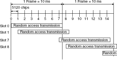
Figure 13.16 RACH access slot numbers and their spacing

Figure 13.17 Structure of the random-access transmission
UE transmits the preamble by random access before sending the message part. When it receives the acquisition indication corresponding to the preamble from the network, UE sends the message part.
RACH Preamble Part: Each preamble is of length 4096 chips and consists of 256 repetitions of a signature of length16 chips Walsh code. The term for the preamble having a repetitive Walsh code is a preamble signature. There are a maximum of 16 available signatures. UE randomly selects one of them prior to each access attempt. The characteristics of the preamble part are:
Channel coding: 256 repetitions of complex signature of length 16
Scrambling: real part of long Gold sequence.
For scrambling code of the preamble part, the code generating method is the same as for the real part of long codes on dedicated channels. Only the first 4096 chips of the code are used for preamble spreading with the chip rate of 3.84 Mcps. The long code Cl for the in-phase components is used directly on both in-phase and quadrature branches without offset between branches. The preamble scrambling code is defined as position-wise mod-2 sum of 4096 chips segments of two binary m-sequences generated by means of two generator polynomials of degree 25.
RACH Message Part: Figure 13.18 shows the structure of the random-access message part in a radio frame. The 10 ms message part radio frame is split into 15 slots, each of length Tslot = 2560 chips. Each slot consists of two parts, a data part to which the RACH transport channel is mapped and a control part that carries layer-1 control information. The data and control parts are transmitted in parallel. A 10 ms message part consists of one message part radio frame, while a 20 ms message part consists of two consecutive 10 ms message part radio frames. The message part length can be determined from the used signature and/or access slot, as configured by higher layers. The data part consists of 10 × 2k bits, where k = 0, 1, 2, 3. This corresponds to a spreading factor of 256, 128, 64, and 32 respectively, for the message data part. The control part consists of 8 known pilot bits to support channel estimation for coherent detection and 2 TFCI bits. This corresponds to a spreading factor of 256 for the message control part. The pilot bit pattern is described in the standard. The total number of TFCI bits in the random-access message is 15 × 2 = 30. The TFCI of a radio frame indicates the transport format of the RACH transport channel mapped to the simultaneously transmitted message part radio frame. For a 20 ms PRACH message part, the TFCI is repeated in the second radio frame.

Figure 13.18 Structure of the random-access message part radio frame
The message part is scrambled with a 10 ms complex code and the scrambling code is cell specific (Figure 13.19). The parameter for the data and control part is shown in Table 13.4.

Figure 13.19 Spreading of PRACH message part
PRACH Transmission Procedure
The following steps are carried out during a random access burst.
- The terminal decodes the BCH (PCCPCH) of the target cell to find out: the cell specific spreading codes available for preamble and message parts, the signatures and access slots available in the cell, the spreading factor allowed for message part, and the PCCPCH transmit power level.
- The mobile randomly selects the signature and access slot to be used for the RACH burst.
- The mobile estimates the downlink path loss and calculates the required uplink transmit power to be used for the random access burst.
- A 1 ms preamble is sent with the selected signature.
- The terminal decodes the AICH to see whether the base station has detected the preamble.
- In case no AICH is detected, the terminal increases the preamble transmission power by a step given by the station, as multiples of 1 dB and transmits in the next available access slot.
- If AICH is received with the signature S of the PRACH, then the message part is sent.
13.6.2.2 Physical Common Packet Channel (PCPCH)
The physical common packet channel (PCPCH) is used to carry the transport channel-CPCH.
CPCH Transmission – The CPCH transmission is based on the DSMA-CD approach with fast acquisition indication. The UE can start the transmission at the beginning of a number of well defined time-intervals, relative to the frame boundary of the received BCH of the current cell. The access slot timing and structure is identical to RACH. The structure of the CPCH access transmission is shown in Figure 13.20. The PCPCH access transmission consists of one or several access preambles (A-P) of length 4096 chips, one collision detection preamble (CD-P) of length 4096 chips, a DPCCH power control preamble (PC-P), which is either 0 slots or 8 slots in length, and a message of variable length N × 10 ms.
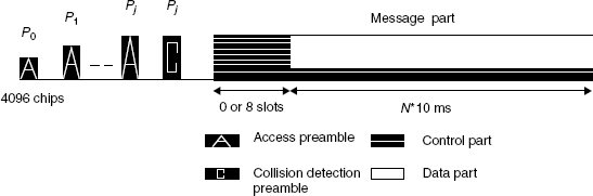
Figure 13.20 Structure of the CPCH access transmission
CPCH Access Preamble Part – Similar to the RACH preamble part, the CPCH preamble signature sequences are used. The number of sequences used could be less than the ones used in the RACH preamble. The scrambling code could either be chosen to be a different code segment of the Gold code used to form the scrambling code of the RACH preambles, or could be the same scrambling code in situations where the signature set is shared.
CPCH Power Control Preamble Part – The power control preamble segment is called the CPCH power control preamble (PC-P) part. The power control preamble length is a parameter which will take the values 0 or 8 slots, as set by the higher layers.
CPCH Message Part – Each message consists of up to N_Max_frames 10 ms frames. N_Max_frames is a higher layer parameter. Each 10 ms frame is split into 15 slots, each of length Tslot = 2560 chips. Each slot consists of two parts, a data part that carries higher layer information and a control part that carries layer-1 control information. The data and control parts are transmitted in parallel. The spreading factor for the control part of the CPCH message part will be 256. The slot format of the control part of the CPCH message part will be the same as the control part of the CPCH PC-P. Each frame of length 10 ms is split into 15 slots, each of length Tslot = 2560 chips, corresponding to one power-control period.
The data part consists of 10 × 2k bits, where k = 0, 1, 2, 3, 4, 5, 6, corresponding to spreading factors of 256, 128, 64, 32, 16, 8, and 4, respectively.
The spreading factor for the control part of the CPCH message part will be 256. The slot format of the control part of the CPCH message part will be the same as the control part of the CPCH PC-P. There are two types of uplink dedicated physical channels; those that include TFCI (for example, for several simultaneous services) and those that do not include TFCI (for example, for fixed-rate services). It is the UTRAN that determines if a TFCI should be transmitted and it is mandatory for all UEs to support the use of TFCI in the uplink.
In the compressed mode, DPCCH slot formats with TFCI fields are changed. There are two possible compressed slot formats for each normal slot format. They are labeled A and B, and the selection between them is dependent on the number of slots that are transmitted in each frame in compressed mode.
Multi-code operation is possible for the uplink dedicated physical channels. When multi-code transmission is used, several parallel DPDCH are transmitted using different channelization codes, however, there is only one DPCCH per radio link.
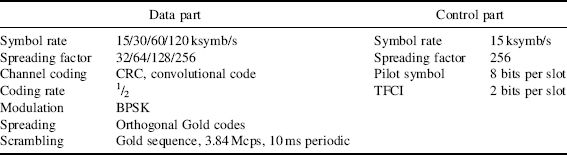
The spreading and modulation of the message part of the PRACH and PCPCH are basically the same as for the uplink dedicated channel consisting of a data channel DPDCH and control channel DPCCH (Figure 13.21). Table 13.5 provides the details for access preamble, CD preamble, CPCH power control and CPCH message part.
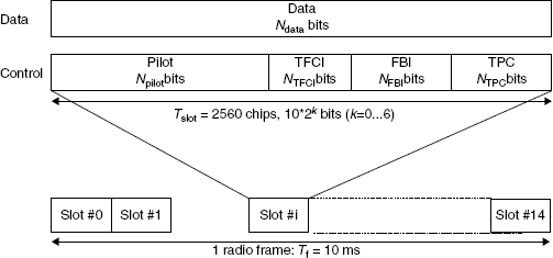
Figure 13.21 Frame structure for uplink data and control parts associated with PCPCH
Table 13.5 Access preamble, CD preamble, CPCH power control and CPCH message part

13.7 Downlink Physical Channels
13.7.1 Dedicated Downlink Physical Channels
There is only one type of downlink dedicated physical channel, which is known as the downlink dedicated physical channel (downlink DPCH). Within one downlink DPCH, dedicated data generated at layer-2 and above, that is, the dedicated transport channel (DCH), is transmitted in time-multiplex with control information generated at layer-1 (known pilot bits, TPC commands, and an optional TFCI). In the downlink direction the DPDCH and DPDCH are time multiplexed as shown in Figure 13.22. Each frame of length 10 ms is split into 15 slots, each of length Tslot = 2560 chips, corresponding to one power-control period.

Figure 13.22 Frame structure for downlink DPCH
The QPSK modulation, where each symbol contains two bits is used in the downlink direction. The parameter k in Figure 13.22 determines the total number of bits per downlink DPCH slot. It is related to the spreading factor SF of the physical channel by SF = 512/2k (where k = 0, …, 7). The spreading factor may thus range from 512 down to 4. Hence, in each slot of length 2560 chips, we are able to put twice the number of bits compared with uplink (BPSK) as QPSK modulation is used. The exact number of bits of the different downlink DPCH fields (Npilot, NTPC, NTFCI, Ndata1, and Ndata2) is given in the standard. Which slot format to use is configured by the higher layers, and can also be reconfigured by the higher layers.
There are basically two types of downlink dedicated physical channels: those that include TFCI (for example, for several simultaneous services), and those that do not include TFCI (for example, for fixed-rate services). It is the UTRAN that determines if a TFCI should be transmitted and it is mandatory for all UEs to support the use of TFCI in the downlink.
DPCH Transmission Procedure
Data modulation is QPSK where each pair of 2 bits is serial-to-parallel converted and mapped to the I- and Q-branch, respectively. The I- and Q-branches are then spread with the same channelization code (real spreading) and subsequently scrambled by the scrambling code (complex scrambling). The channelization code is derived from the OVSF code tree based on the SF used, and the scrambling code is the sector (base station) specific scrambling code (Figure 13.23). Parameters for downlink DPCH are given in Table 13.6.
Table 13.6 Parameters for downlink DPCH
| Channel coding | CRC, convolutional code, Turbo code (according to Qos) in DPDCH |
| Symbol rate | 7.5/15/30/60/120/240/480/960 ksymb/s |
| Spreading factor | 4/8/16/32/64/128/256/512 |
| Modulation | QPSK |
| Spreading | OVSF codes |
| Scrambling | Gold sequence, 3.84 Mcps, 10 ms periodic |
| Power control period | 0.625 ms |
| Pilot symbol | Include |
| TFCI bits | Include |
| TPC bit | Include |
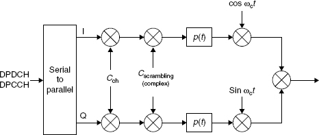
Figure 13.23 Downlink spreading arrangement and modulation
In compressed mode, a different slot format is used compared with normal mode. There are two possible compressed slot formats, which are labeled A and B. Format B is used for compressed mode by spreading factor reduction and format A is used for all other transmission time reduction methods.
13.7.2 Common Downlink Physical Channels
13.7.2.1 Common Pilot Channel (CPICH)
The pilot channel is used by the base station to provide a reference to all mobile stations and to aid the channel estimation at the terminals. It provides phase reference for coherent demodulation at the mobile receiver to enable coherent detection. This is an unmodulated code channel, which is scrambled with the cell-specific primary scrambling code. It has a predefined bit sequence, which for a single transmit antenna is an all logical 1 sequence. The CPICH is a fixed rate (30 kbps, SF = 256) downlink physical channel that carries a pre-defined bit/symbol sequence. Figure 13.24 shows the frame structure of the CPICH.
There are two types of CPICH: primary and secondary. The P-CPICH provides a coherent reference to obtain the SCH, P-CCPCH, AICH and PICH at the UEs, as these channels do not carry their own pilot information. The channelization code used by the P-CPICH is Cch,256.0, an all logical 1 code, while its scrambling code is the cell's primary scrambling code. In the case of a single transmit antenna, the CPICH is the unmodulated primary scrambling code. There is only one P-CPICH in each cell, and this is broadcast over the entire cell.

Figure 13.24 Frame structure for common pilot channel
UE estimates the channel impulse response from the received pilot signal, and armed with this response the data may be recovered. Thus the pilot and data must be transmitted over the same radio channel (which includes the transmitter and receiver antenna). Consequently, as the CPICH is transmitted over the entire cell or sector, it cannot be used to recover data from a narrow beam of a smart antenna because the radio channels for the data and CPICH may be very different. A smart antenna with its narrow beams will create radio channels with few or no significant multipath components, unlike a wide angle beam.
The secondary common pilot channel (S-CPICH) provides a common coherent reference within part of a cell or sector. The antenna have narrow beams, for example, from a smart antenna, and may be used to target individual UEs or groups of UEs in close proximity to one another.
The Node B (a BS) may use any channelization code having a length of 256 chips. The SCPICH may be used as reference for the S-CCPCH (which transmits paging messages) and the downlink dedicated channels.
There are two types of common pilot channels, the primary and secondary CPICH. They differ in their use and the limitations placed on their physical features.
Primary Common Pilot Channel (P-CPICH)
The primary common pilot channel (P-CPICH) has the following characteristics.
- The same channelization code is always used for the P-CPICH.
- The P-CPICH is scrambled by the primary scrambling code.
- There is one and only one P-CPICH per cell.
- The P-CPICH is broadcast over the entire cell.
The primary CPICH is the phase reference for the following downlink channels: SCH, primary CCPCH, AICH, and PICH. The primary CPICH is also the default phase reference for all other downlink physical channels.
Secondary Common Pilot Channel (S-CPICH)
A secondary common pilot channel (S-CPICH) has the following characteristics.
- An arbitrary channelization code of SF = 256 is used for the S-CPICH.
- An S-CPICH is scrambled by either the primary or a secondary scrambling code.
- There may be zero, one, or several S-CPICH per cell.
- An S-CPICH may be transmitted over the entire cell or only over a part of the cell.
- An S-CPICH may be the reference for the S-CCPCH and the downlink DPCH. If this is the case, the UE is informed about this by higher-layer signaling.
13.7.2.2 Primary Common Control Physical Channel (P-CCPCH)
The primary CCPCH is a fixed rate (30 kbps, SF = 256) downlink physical channel used to carry the BCH transport channel. Figure 13.25 shows the frame structure of the primary CCPCH. The frame structure differs from the downlink DPCH in that no TPC commands, no TFCI, and no pilot bits are transmitted. The primary CCPCH is not transmitted during the first 256 chips of each slot. Instead, primary SCH and secondary SCH are transmitted during this period. Table 13.7 tabulates the parameters for PCCPCH.
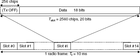
Figure 13.25 Frame structure for primary common control physical channel
Table 13.7 Parameters for PCCPCH
| Channel coding | CRC, convolutional code |
| Symbol rate | 30 ksymb/s |
| Spreading factor | 256 |
| Modulation | QPSK |
| Spreading | Predefined code (Cch,256.1) |
| Scrambling | Gold sequence, 3.84 Mcps, 10 ms periodic, primary scrambling code of the sector |
| Power control | Not supported |
| Pilot symbol | Include |
| TFCI bits | Not included |
13.7.2.3 Secondary Common Control Physical Channel (S-CCPCH)
The secondary CCPCH is used to carry the FACH and PCH. There are two types of secondary CCPCH: those that include TFCI and those that do not include TFCI. It is the UTRAN that determines if a TFCI should be transmitted, hence making it mandatory for all UEs to support the use of TFCI. The set of possible rates for the secondary CCPCH is the same as for the downlink DPCH. The frame structure of the secondary CCPCH is shown in Figure 13.26.

Figure 13.26 Frame structure for secondary common control physical channel
The parameter k in Figure 13.26 determines the total number of bits per downlink secondary CCPCH slot. It is related to the spreading factor SF of the physical channel as SF = 256/2k. The spreading factor range is from 256 down to 4.
The FACH and PCH can be mapped to the same or to separate secondary CCPCHs. If FACH and PCH are mapped to the same secondary CCPCH, they can be mapped to the same frame. The main difference between a CCPCH and a downlink dedicated physical channel is that a CCPCH is not inner-loop power controlled. The main difference between the primary and secondary CCPCH is that the transport channel mapped to the primary CCPCH (BCH) can only have a fixed predefined transport format combination, while the secondary CCPCH support multiple transport format combinations using TFCI. Furthermore, a primary CCPCH is transmitted over the entire cell while a secondary CCPCH may be transmitted in a narrow lobe in the same way as a dedicated physical channel (only valid for a secondary CCPCH carrying the FACH). Parameters for SCCPCH are mentioned in Table 13.8.
Table 13.8 Parameters for SCCPCH
| Channel coding | CRC, convolutional code |
| Symbol rate | 15/30/60/120/240/480/960 ksymb/s |
| Modulation | QPSK |
| Spreading | Predefined code broadcast on the BCH |
| Scrambling | Gold sequence, 3.84 Mcps, 10 ms periodic |
| Power control | Not supported |
| Pilot symbol | Include |
| TFCI bits | Included/not include |
13.7.2.4 Synchronization Channel (SCH)
The synchronization channel (SCH) is a downlink channel used for initial synchronization purposes and cell search. The SCH consists of two subchannels, the primary and secondary SCH. The 10 ms radio frames of the primary and secondary SCH are divided into 15 slots, each of length 2560 chips. Figure 13.27 illustrates the structure of the SCH radio frame.

Figure 13.27 Structure of synchronization channel (SCH)
The primary SCH consists of a modulated code of length 256 chips, the primary synchronization code (PSC) denoted cp in Figure 13.27, is transmitted once every slot. The PSC is the same for every cell in the system.
The secondary SCH consists of repeatedly transmitting a length of 15 sequences of modulated codes of length 256 chips, the secondary synchronization codes (SSC), transmitted in parallel with the primary SCH. The SSC is denoted aci,ks in Figure 13.27, where i = 0, 1, …, 63 is the number of the scrambling code group, and k = 0, 1, …, 14 is the slot number. Each SSC is chosen from a set of 16 different codes of length 256. This sequence on the secondary SCH indicates which of the code groups the cell's downlink scrambling code belongs to (Figure 13.28).

Figure 13.28 Spreading and scrambling for PCCPCH, SCCPCH, and SCH channels
13.7.2.5 Physical Downlink Shared Channel (PDSCH)
The physical downlink shared channel (PDSCH), used to carry the downlink shared channel (DSCH) transport channel, is shared by users based on code multiplexing. As the DSCH is always associated with one or several DCHs, the PDSCH is always associated with one or several downlink DPCHs. More exactly, each PDSCH radio frame is associated with one downlink DPCH.
The frame and slot structure of the PDSCH are shown on Figure 13.29.
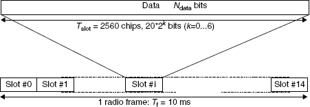
Figure 13.29 Frame structure for the PDSCH
To indicate for UE that there are data to decode on the DSCH, two signaling methods are used, either the TFCI field, or higher layer signaling.
The PDSCH transmission with associated DPCH is a special case of multi-code transmission. The PDSCH and DPCH do not =necessarily have the same spreading factors. Furthermore, the PDSCH spreading factors may vary from frame to frame. All relevant layer-1 control information is transmitted on the DPCCH part of the associated DPCH, that is, the PDSCH does not carry physical layer information. For PDSCH, the allowed spreading factors may vary from 256 to 4.
If the spreading factor and other physical layer parameters can vary on a frame-by-frame basis, the TFCI will be used to inform the UE what are the instantaneous parameters of PDSCH, including the channelization code from the PDSCH OVSF code tree. A DSCH may be mapped to multiple parallel PDSCHs. In such a case the parallel PDSCHs will be operated with frame synchronization between each other and the spreading factors of all PDSCH codes will be the same. PDSCH parameters are mentioned in Table 13.9.
Table 13.9 Parameters for PDSCH
| Channel coding | CRC, convolutional code, and Turbo code (according to Qos) |
| Symbol rate | 15/30/60/120/240/480/960 ksymb/s |
| Modulation | QPSK |
| Spreading | OVSF code |
| Scrambling | Gold sequence, 3.84 Mcps, 10 ms periodic, primary scrambling code |
| Power control | Supported by associated DCH |
| Pilot symbol | Not include |
| TFCI bits | Supported by associated DCH |
13.7.2.6 Acquisition Indication Channel (AICH)
The acquisition indication channel (AICH) is a physical channel used to carry the acquisition indicators (AI). Acquisition indicator AIs corresponds to the signature S of the PRACH.
Figure 13.30 shows the structure of the AICH, which consists of a repeated sequence of 15 consecutive access slots (AS), each of length 40-bit intervals. Each access slot consists of two parts, an acquisition indicator (AI) part consisting of 32 real-valued symbols a0, …, a31 and a part of 1024 chips duration with no transmission.

Figure 13.30 Structure of acquisition indication channel (AICH)
The phase reference for the AICH is the primary CPICH.
The real-valued symbols a0, a1, …, a31 in Figure 13.30 are given by:
![]()
where AIs, taking the values +1, −1, and 0, is the acquisition indicator corresponding to signature S and the sequence bs, 0, …, bs, 31 is given in the standard. Parameters for AICH are shown in Table 13.10.
Table 13.10 Parameters for AICH
| Channel coding | Orthogonal code |
| Symbol rate | 15 ksymb/s |
| Spreading factor | 256 |
| Spreading code | OVSF |
| Scrambling | Gold sequence, 3.84 Mcps, 10 ms periodic |
13.7.2.7 Paging Indicator Channel (PICH)
The paging indicator channel (PICH) is always associated with a paging channel (PCH) on S-CCPCH. The PICH carries the page indicators (PIs), where PI indicates the subset of UEs within a cell whether they should check the next S-CCPCH frame for paging messages. UE in idle mode receives nothing but the PI. UE receives PCH in the radio frame of the S-CCPCH corresponding to the PI, only when it is informed of an incoming call by the PI. PIs are divided into several groups. This helps to save battery life. The paging indicator channel (PICH) is a fixed rate (SF = 256) physical channel used to carry the paging indicators (PI). The PICH is always associated with an S-CCPCH to which a PCH transport channel is mapped.
Figure 13.31 illustrates the frame structure of the PICH. One PICH radio frame of length 10 ms consists of 300 bits (b0, b1, …, b299). Of these, 288 bits (b0, b1, …, b287) are used to carry paging indicators. The remaining 12 bits (b288, b289, …, b299) are undefined.
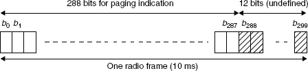
Figure 13.31 Structure of paging indicator channel (PICH)
N paging indicators {PI0, …, PIN−1} are transmitted in each PICH frame, where N = 18, 36, 72, or 144.
The PI calculated by higher layers for use for a certain UE, is mapped to the paging indicator PIp, where p is computed as a function of the PI computed by higher layers, the SFN of the P-CCPCH radio frame during which the start of the PICH radio frame occurs, and the number of paging indicators per frame (N):
![]()
If a paging indicator in a certain frame is set to “1,” it is an indication that UEs associated with this paging indicator should read the corresponding frame of the associated S-CCPCH. PICH parameters are mentioned in Table 13.11.
Table 13.11 Parameters for PICH
| Symbol rate | 15 ksymb/s |
| Spreading factor | 256 |
| Spreading code | OVSF |
| Scrambling | Gold sequence, 3.84 Mcps, 10 ms periodic |
| Number of PI | 18/36/72/144 |
There are some other channels are also defined, such as: the CPCH status indicator channel (CSICH), which is a fixed rate (SF = 256) physical channel used to carry CPCH status information; the collision detection channel assignment indicator channel (CD/CA-ICH), which is a physical channel used to carry the CD indicator (CDI) only if the CA is not active, or CD indicator/CA indicator (CDI/CAI) at the same time if the CA is active, and so on.
13.8 Timing Relationship between Physical Channels
The P-CCPCH, on which the cell SFN is transmitted, is used as a timing reference for all the physical channels, directly for downlink and indirectly for uplink. SCH (primary and secondary), CPICH (primary and secondary), P-CCPCH, and PDSCH have identical frame timings. The S-CCPCH timing may be different for different S-CCPCHs, but the offset from the P-CCPCH frame timing is a multiple of 256 chips. The PICH timing is tPICH = 7680 chips prior to its corresponding S-CCPCH frame timing, that is, the timing of the S-CCPCH carrying the PCH transport channel with the corresponding paging information. AICH access slots 0 start at the same time as P-CCPCH frames with (SFN modulo 2) = 0. The DPCH timing may be different for different DPCHs, but the offset from the P-CCPCH frame timing is a multiple of 256 chips.
13.8.1 Channel Number and Bands
The carrier frequency is designated by the UTRA absolute radio frequency channel number (UARFCN). For each operating band, the UARFCN values are defined as follows:
Uplink: NU = 5*(FUL − FUL_offset), for the carrier frequency range FUL_low ≤ FUL ≤ FUL_high
Downlink: ND = 5*(FDL − FDL_offset), for the carrier frequency range FDL_low ≤ FDL ≤ FDL_high
13.9 Transmitter Characteristics
UE Maximum Output Power – Different power classes are defined for nominal maximum output power: power class-1, -2, -3, and -4. For band-I, the power is defined as +33 dBm for class-1, +27 dBm for class-2, +24 dBm for class-3, and +21 dBm for class-4. The nominal power defined is the broadband transmit power of the UE, that is, the power in a bandwidth of at least (1 + α) times the chip rate of the radio access mode.
Frequency Error – The UE modulated carrier frequency should be accurate within ±0.1 ppm, observed over a period of one time slot compared with the carrier frequency received from Node B. For the PRACH preambles the measurement interval is lengthened to 3904 chips (this being the 4096 chip nominal preamble period less a 25 μs transient period allowance at each end of the burst). The UE willl use the same frequency source for both RF frequency generation and the chip clock.
Power Control – Open loop power control is the ability of the UE transmitter to set its output power to a specific value. The UE open loop power is defined as the mean power in a time slot or ON power duration, whichever is available. In normal conditions the tolerance is ±9 dB. Inner loop power control in the uplink is the ability of the UE transmitter to adjust its output power in accordance with one or more TPC commands received in the downlink.
Diversity Characteristics – Three forms of diversity are considered to be available in UTRA/FDD. (1) Time diversity – channel coding and interleaving in both uplink and downlink. (2) Multi-path diversity – Rake receiver or other suitable receiver structure with maximum combining; additional processing elements can increase the delay-spread performance due to increased capture of signal energy. (3) Antenna diversity – antenna diversity with maximum ratio combing in Node B and optionally in the UE.
Reference Sensitivity Level – The reference sensitivity level is the minimum mean power received at the UE antenna port at which the bit error ratio (BER) should not exceed a specific value. The minimum requirement is that the BER should not exceed 0.001 for different bands as specified in the standard. For example, DPCH_Ec < reference sensitivity > −117 for operating bands 1 and 4 unit dBm/3.84 MHz.
13.10 Different Channel Usage in Various Scenarios
As discussed earlier, in the downlink direction some channels are transmitted continuously in each cell, these are treated as overhead channels (Figure 13.32). They are used by the UE to synchronize to the cell, to identify the cell and the network, and to obtain information about how to access the cell.
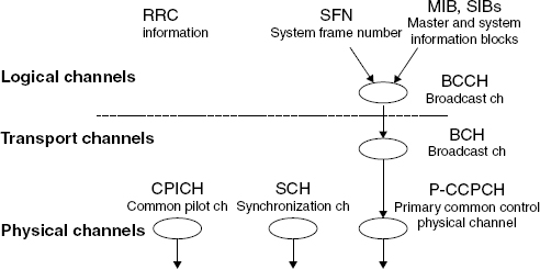
Figure 13.32 Downlink channel usage
The common pilot channel (CPICH) is used to transmit timing and frequency reference information to UEs (mobile stations) that are used by the UE (mobile station) to find the primary scrambling code and to help determine its transmit power during open loop power control. The synchronization channel (SCH) includes the primary and secondary synchronization channels (PSC and SSC) that contain timing information to allow the UE to synchronize to the base station. It is time multiplexed with P-CCPCH. The primary common control physical channel (P-CCPCH) is used to transmit the broadcast transport channel (BCH), which provides system information to the UE. It is time multiplexed with the synchronization channel (SCH), which is used to aid the UE synchronization to the network. In the FDD test operating mode, this channel consists of pseudo-random bit sequence (PRBS) data and a valid system frame number (SFN).
13.10.1 Channel Used for Call Setup
After the UE has identified a cell that it wants to access and has read the access information from the broadcast channel, it must register. Registration informs the network of the presence of the UE and is performed using the location update procedure.
In order to make the communication between the mobile and the network a control connection must be established between the RRC entities of the network side and the UE side. This step is the same whether the purpose is registration, mobile initiated call setup, or network originated call setup. These channels are shown in Figure 13.33 as W-CDMA connection setup channels.
Physical Random Access Channel – Used by the UE to make its initial transmissions to the network.
Acquisition Indication Channel (AICH) – Used to acknowledge UE access request.
Paging Indication Channel (PICH) – Used to alert the UE of a forthcoming page message. In FDD test mode, the test set only provides a user specified bit pattern to allow the operator to verify that the UE is correctly decoding this channel.

Figure 13.33 Channel usage for call setup
Secondary Common Control Physical Channel (S-CCPCH) – Used to transmit pages and signaling to idling UEs.
13.11 Compressed Mode
Compressed mode is a function that enables the measurement of cells with different frequencies for the purpose of carrying out handover between the different frequencies. The support of the downlink compressed mode is essential for a single carrier UE. The decision to migrate to compressed mode is made by UTRAN, which informs UE of the parameters required for compressed mode. In compressed mode no data transmission takes place in the slot referred to as the transmission gap (Figure 13.34). In a frame of compressed mode, the transmission power is raised temporarily to prevent the degradation in quality due to the lower gain caused by the suspension of transmission. Various methods for creating the compressed mode are given in the Table 13.12.

Figure 13.34 Compressed mode
Table 13.12 Different methods of compressed mode
| Method | Overview |
| Compressed mode by puncturing | A way to reduce the number of transmitted bits by using rate matching function. The same SF is used in compressed mode as in the normal mode. |
| Compressed mode by reducing the SF by 2 | A way to temporarily increase the transmission speed by halving SF so that the same number of bits can be transmitted as in the normal mode in slots other than the transmission gap. |
| Compressed mode by higher layer scheduling | A way to limit the transport format set by the higher layer according to the number of bits that can be transmitted in slots other than the transmission gap. The same SF is used in compressed mode as in normal mode. It is basically applicable to non-real time services such as packet transmission. |
The rate and type of compressed frames is variable and depends on the environment and the measurement requirements. There are two different types of frame structures defined for downlink compressed frames. Type A maximizes the transmission gap length and type B is optimized for power control. The frame structure type A or B is set by higher layers independent of the downlink slot format type A or B.
Further Reading
3GPP Technical Specification Group Radio Access Network. Physical Channels and Mapping of Transport Channels (FDD), 3GPP, TS 25.211, Version 3.0.0. ETSI TC-SMG, Sophia-Antipolis Cedex.
3GPP Technical Specification Group Radio Access Network. Spreading and Modulation (FDD), 3GPP, TS 25.213, Version 3.0.0. ETSI TC-SMG, Sophia-Antipolis Cedex.
3GPP Technical Specification Group (TSG) RAN WG4 UTRA (BS) FDD. Radio Transmission and Reception, 3GPP, TS 25.104, Version 3.0.0, www.3gpp.org/Specifications.
Goodman, D.J. (1997) Wireless Personal Communication Systems, Addison-Wesley, London.
Zvonar, Z., Jung, P., and Kammerlander, K. (1999) GSM, Evolution Towards 3rd Generation Systems, Kluwer Academic Press, Dordrecht.